
CONTENTS
1.1 Development of Underground Cables
1.4 Distribution of Energy for Lighting
1.6 Underground Residential Distribution Systems
1.7 Extruded Dielectric Power Cables
1.9 Medium Voltage Cable Development
1.1 DEVELOPMENT OF UNDERGROUND CABLES
In order to trace the history of underground cable systems, it is necessary to examine the early days of the telegraph [1,2]. The telegraph was the first device utilizing electrical energy to become of any commercial importance and its development necessarily required the use of underground construction. Accordingly, experimentation with underground cables was carried on contemporaneously with the development of the apparatus for sending and receiving signals. Underground construction was planned for most of the earliest commercial lines. A number of these early installations are of considerable interest as marking steps in the development of the extensive underground power systems in operation around the world.
In 1812, Baron Schilling detonated a mine under the Neva River at St. Petersburg, Russia, by using an electrical pulse sent through a cable insulated with strips of India rubber. This is probably the earliest use of a continuously insulated conductor on record. One of the earliest experiments with an underground cable was carried out by Francis Ronalds in 1816. This work was in conjunction with a system of telegraphy consisting of 500 feet of bare copper conductor drawn into glass tubes, joined together with sleeve joints, and sealed with wax. The tubes were placed in a creosoted wooden trough buried in the ground. Ronalds was very enthusiastic over the success of this line, predicting that underground conductors would be widely used for electrical purposes and outlining many of the essential characteristics of a modern distribution system.
The conductor in this case was first insulated with cotton saturated with shellac before being drawn into the tubes. Later, strips of India rubber were used. This installation had many insulation failures and was abandoned. No serious attempt was made to develop the idea commercially.
In 1837, W. R. Cooke and Charles Wheatstone laid an underground line along the railroad right-of-way between London’s Euston and Camden stations for their five-wire system of telegraphy. The wires were insulated with cotton saturated in rosin and were installed in separate grooves in a piece of timber coated with pitch. This line operated satisfactorily for a short time, but a number of insulation failures due to the absorption of moisture led to its abandonment. The next year, Cooke and Wheatstone installed a line between Paddington and Drayton stations in London, but iron pipe was substituted for timber to give better protection from moisture. Insulation failures also occurred on this line after a short time, and it was also abandoned.
In 1842, S. F. B. Morse laid a cable insulated with jute, saturated in pitch, and covered with strips of India rubber, between Governor’s Island and Castle Garden in New York harbor. The next year, a similar line was laid across a canal in Washington, DC. The success of these experiments induced Morse to write to the Secretary of the Treasury that he believed “telegraphic communications on the electro-magnetic plan can with a certainty be established across the Atlantic Ocean.”
In 1844, Morse obtained an appropriation from the U.S. Congress for a telegraph line between Washington and Baltimore. An underground conductor was planned and several miles were actually laid before the insulation was proved to be defective. The underground project was abandoned and an overhead line erected. The conductor was originally planned to be a #16 gage copper insulated with cotton and saturated in shellac. Four insulated wires were drawn into a close-fitting lead pipe, which was then passed between rollers and drawn down into close contact with the conductors. The cable was coiled on drums in 300-foot lengths and laid by means of a specially designed plow.
Thus, the first attempts at underground construction were unsuccessful, and overhead construction was necessary to ensure satisfactory performance of the lines. After the failure of Morse’s line, no additional attempts were made to utilize underground construction in the United States until Thomas A. Edison’s time.
Gutta-percha—a natural, thermoplastic rubber—was introduced in Europe in 1842 by Dr. W. Montgomery, and in 1846 was adopted upon the recommendation of Dr. Werner Siemens for the telegraph line that the Prussian government was installing. Approximately 3,000 miles of such wire were laid from 1847 to 1852. Unfortunately, the perishable nature of the material was not known at the time and no adequate means of protecting it from oxidation was provided. Insulation troubles soon began to develop and eventually became so serious that the entire installation was abandoned.
However, gutta-percha provided a very satisfactory material for insulating telegraph cables when properly protected from oxidation. It was used extensively for both underground and submarine installations.
In 1860, vulcanized rubber was used for the first time as insulation for wires. Unvulcanized rubber had been used on several of the very early lines in strips applied over fibrous insulation for moisture protection. This system had generally been unsatisfactory because of difficulties in closing the seam. Vulcanized rubber proved to be a much better insulating material, but did not become a serious competitor of gutta-percha until some years later.
While early telegraph systems were being developed, other experimenters were solving the problems related to the commercial development of electric lighting. An electric light required a steady flow of a considerable amount of energy, and was consequently dependent upon the development of the dynamo. The first lamps were designed to utilize the electric arc that had been demonstrated by Sir Humphry Davy as early as 1810. Arc lights were brought to a high state of development by Paul Jablochkoff in 1876 and by C. R. Brush in 1879. Both men developed systems for lighting the streets with arc lamps connected in series supplied from a single generating station.
Lighting by incandescence was principally the result of the work of Thomas A. Edison, who developed a complete system of such lighting in 1879. His lights were designed to operate in parallel instead of in series, as had been the case with the previously developed arc-lighting systems. This radical departure from precedent permitted the use of low voltage and greatly simplified the distribution problems.
1.4 DISTRIBUTION OF ENERGY FOR LIGHTING
Edison planned his first installation in a densely populated area of lower Manhattan in New York City, and decided that an underground system of distribution would be necessary. This took the form of a network supplied by feeders radiating from a centrally located direct current (DC)-generating station to various feed points in the network. Pilot wires were taken back to the generating station from the feed points to give the operator an indication of voltage conditions on the system. Regulation was controlled by cutting feeders in, or out, as needed. At a later date, a battery was connected in parallel with the generator to guard against a station outage (Figures 1.1 and 1.2).
Gutta-percha, which had proved to be a satisfactory material for insulating the telegraph cables, was not suitable for the lighting feeders because of the softening of the material (a natural thermoplastic) at relatively high operating temperature. Experience with other types of insulation had not been sufficient to provide any degree of satisfaction with their use. The development of a cable sufficiently flexible to be drawn into ducts was accordingly considered a rather remote possibility. Therefore, Edison designed a rigid, buried system consisting of copper rods insulated with a wrapping of jute. Two or three insulated rods were drawn into iron pipes and a heavy bituminous compound was forced in and around them. They were then laid in 20-foot sections and joined together with specially designed tube joints from which taps could be taken if desired. The Edison tube gave a remarkably satisfactory performance for this class of low voltage service.
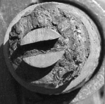
FIGURE 1.1 Early Edison cable. Photos courtesy of Robert Lobenstein/IEEE Power & Energy.
The low voltage and heavy current characteristics of DC distribution were limited to the area capable of being supplied from one source if the regulation was to be kept within reasonable bounds. The high first cost and heavy losses made such systems uneconomical for general distribution. Accordingly, they were developed in limited areas of high-load density such as the business districts of large cities.
In the outlying districts, alternating current (AC) distribution was universally employed. This type of distribution was developed largely as a result of the work in 1882 of Lucien Gaulard and J. D. Gibbs, who designed a crude AC system using induction coils as transformers. The coils were first connected in series, but satisfactory performance could not be obtained. However, they were able to distribute electrical energy at a voltage considerably higher than that required for lighting and demonstrate the economics of the AC system. This system was introduced in the United States in 1885 by George Westinghouse, and served as the basis for the development of workable systems. An experimental installation went into service at Great Barrington, Massachusetts, early in 1886. The first large-scale commercial installation was built in Buffalo, New York, the same year.
The early installations operated at 1,000 volts. Overhead construction was considered essential for their satisfactory performance and almost universally employed. This was also true of the street-lighting feeders, that operated at about 2,000 volts. In Washington and Chicago, overhead wires were prohibited, so a number of underground lines were installed. Many different types of insulation and methods of installation were tried with little success. Experiments with underground conductors were also carried out in Philadelphia. The 1884 enactment of a law forcing the removal of all overhead wires from the streets of New York City mandated the development of a type of construction that could withstand such voltages. It was some time, however, before the overhead high-voltage wires disappeared. In 1888, the situation was summarized in a paper before the National Electric Light Association [1] as follows:
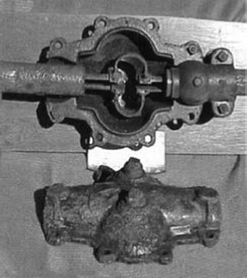
FIGURE 1.2 Splice box. Photos courtesy of Robert Lobenstein/IEEE Power & Energy.
No arc wires had been placed underground in either New York or Brooklyn. The experience in Washington led to the statement that no insulation could be found that would operate two years at 2,000 volts. In Chicago, all installations failed with the exception of lead covered cables which appeared to be operating successfully. In Milwaukee, three different systems had been tried and abandoned. In Detroit, a cable had been installed in Dorsett conduit, but later abandoned. In many of the larger cities, low voltage cables were operating satisfactorily and in Pittsburgh, Denver and Springfield, Mass., some 1,000 volt circuits were in operation. (Underground Systems Reference Book 1931, 2).
The first important line insulated with paper was installed by Sebastian de Ferranti in 1890 between Deptford (on the south side of the River Thames) and the City of London, for single-phase operation at 10,000 volts [3]. Some of these mains were still in use at the original voltage after more than 50 years. The cables consisted of two concentric copper conductors insulated with wide strips of paper applied helically around the conductor and saturated with a rosin-based oil. The insulated conductors were forced into an iron pipe filled with bitumen and installed in 20-foot lengths inside train tunnels under the river. This system operated successfully for 43 years and may be the source of the “40 year life” of power cables [4].
In the period between 1885 and 1887, cables insulated with helically applied narrow paper strips saturated with paraffin and later in a rosin compound and covered with a lead sheath (very similar in design to those used at the present time) were manufactured in the United States by the Norwich Wire Company. These were the first flexible paper-insulated cables, and all subsequent progress has been made through improvements in the general design.
Paper-insulated cables were improved through the following years by:
1. The introduction of the shielded design of multiple conductor cables by Martin Hochstadter in 1914. This cable is still known as Type H.
2. Luigi Emanueli’s demonstration in 1920 that voids due to expansion and contraction could be controlled by the use of a thin oil impregnating fluid and reservoirs. This permitted the voltages to be raised to 69 kV and higher.
3. The 1927 patent by H. W. Fisher and R. W. Atkinson revealed that the dielectric strength of impregnated paper-insulated cable could be greatly increased by maintaining the insulating system under pressure. This system was not used commercially until the 1932 installation of a 200 psi pressurized cable in London.
Impregnated paper became the most common form of insulation for cables used for bulk transmission and distribution of electrical power, particularly for operating voltages of 12.5 kV and above, where low dielectric loss, low dissipation factor, and high ionization level are important factors in determining the cable life.
Impregnated paper insulation consists of multiple layers of paper tapes, each tape from 2.5 to 7.5 mils in thickness, wrapped helically around the conductor to be insulated. The entire wall of paper tapes is then heated, vacuum dried, and impregnated with an insulating fluid. The quality of the impregnated paper insulation depends not only on the properties and characteristics of the paper and impregnating fluid, but also on the mechanical application of the paper tapes over the conductor, the thoroughness of the vacuum drying, and the control of the saturating and cooling cycles during the manufacturing.
Originally, most of the paper used was made from Manila-rope fiber. This was erratic in its physical properties and not always susceptible to adequate oil penetration. Increased knowledge of the chemical treatment of the wood (in order to obtain pure cellulose by the adjustment of the fiber content and removal of lignin), the control of tear resistance, and the availability of long fiber stock resulted in the almost universal use of wood pulp paper in cables after 1900.
The impregnating compound was changed from a rosin-based compound to a pure mineral oil circa 1925, or oil blended to obtain higher viscosity, until polybutene replaced oil circa 1983.
Paper-insulated, lead-covered cables were the predominant power cables of all the large, metropolitan transmission and distribution systems in the United States, and the rest of the world, throughout the twentieth century. Their reliability was excellent. It was, however, necessary to have a high degree of skill for proper splicing and terminating. A shift toward extruded dielectric cables began about 1975 in those metropolitan areas, but the majority of the distribution cables of the large cities remained paper-insulated, lead-covered cables as the century ended.
Considerable research has been carried out by the utilities, technical organizations, and manufacturers of cables to obtain improved paper and laminated polypropylene-paper-polypropylene (PPP, now used in transmission cables) tapes and insulating fluids that are able to withstand high, continuous operating temperatures.
Impregnated paper insulation has excellent electrical properties, such as high dielectric strength, low dissipation factor, and dielectric loss. Because of these properties, the thickness of impregnated paper insulation was considerably less than for rubber or varnished cambric insulations for the same working voltages. Polyethylene and cross-linked polyethylene cables in the distribution classes are frequently made with the same wall thickness as today’s impregnated paper cables.
1.6 UNDERGROUND RESIDENTIAL DISTRIBUTION SYSTEMS
The development of modern underground residential distribution (URD) systems may be viewed as the result of drastically lowering first costs through technology. Post-war URD systems were basically the same as the earlier systems except that there were two directions of feed (the loop system.) System voltages rose from 2,400/4,160 to 7,620/13,200 volts. The pre-1950 systems were very expensive because they utilized items such as paper insulated cables, vaults, switches, and submersible transformers. Those systems had an installation cost of $1,000 to $1,500. Expressed in terms of buying power at that time, you could buy a luxury car for the same price! Underground service was, therefore, limited to the most exclusive housing developments.
But for three developments in the 1960s, the underground distribution systems that exist today might not be in place. First, in 1958–1959, a large Midwestern utility inspired the development of the pad-mounted transformer; the vault was no longer necessary, nor was the submersible transformer. Second, the polyethylene cable with its bare concentric neutral did not require cable splicers, and the cable could be directly buried. While possibly not as revolutionary, the load-break elbow (separable connector) allowed the transformer to be built with a lower, more pleasing appearance.
The booming American economy and the environmental concerns of the nation made underground utility systems for new residential subdivisions the watchword of the Great Society. In a decade, URD had changed from a luxury to a necessity. The goal for the utility engineer was to design a URD system at about the same cost as the equivalent overhead system. There was little or no concern about costs over the system’s life because the polyethylene cable was expected to last 100 years!
1.7 EXTRUDED DIELECTRIC POWER CABLES
The use of natural and synthetic polymers for industrial applications (during and after World War II) led to this technology being applied for cable insulation; in contrast to paper-insulated cables, these polymers could be extruded. Natural rubber was used first and synthetic rubber followed; as developments continued, butyl rubber became a material of choice for cable insulation for a while. Further developments led to newer synthetic elastomeric (rubbery) polymers, such as Neoprene (1931), chloroprene, and Hypalon (1951). The newer polymers, as they were developed, facilitated improvements in processing or properties (e.g., longer term reliability on aging, or flame resistance) and all were used concurrently depending on the application. Ethylenepropylene polymers (EPR) were employed in the 1960s as replacement for butyl rubber, but their usage, while steady, did not increase until the 1980s. It is to be noted that improvement in the insulation properties of elastomers was related not only to the polymer itself but also to the nature of the additives used.
High molecular weight polyethylene (HMWPE), which is not an elastomer, was extrudable and its development (starting in 1941) triggered a dramatic change in the insulation of cables for the transmission and distribution of electrical energy. Thermoplastic polyethylene was actually introduced during World War II for high-frequency cable insulation. By 1947, HMWPE was furnished as 15 kV cable insulation. Wide usage began with the advent of URD systems in the early 1960s. In the mid-1960s, conventional HMWPE was the material of choice for the rapidly expanding URD systems in the United States. It was superior to butyl rubber for electrical properties and moisture resistance. These cables were used as loop circuits for #2 and #1/0 AWG cables. The domination of polyethylene lasted until the mid-1970s.
Further discussion of the more modern insulation materials such as HMWPE, cross-linked polyethylene (XLPE), and EPR is in Chapter 5, “Electrical Insulation Materials.”
During the mid-1970s, reports of early cable failures in extruded dielectric systems began to be documented in many parts of the world. “Treeing” was reintroduced to the cable engineer’s vocabulary. This time it did not have the same meaning as with paper-insulated cables. See Chapter 17 for additional information on treeing.
By 1976, reports from utilities [4] and results of Electric Power Research Institute (EPRI) research [5] confirmed the fact that some thermoplastic polyethylene insulated cables (HMWPE) were failing in service in less than 5 years and failures were occurring at a rapidly increasing rate. By 1980, production of medium voltage HMWPE ceased in North America.
XLPE exhibited a much lower failure rate which was not escalating nearly as rapidly. Data from Europe confirmed the same facts in a report prepared by UNIPEDEDISCAB. XLPE had been commercially available since 1963, but its slightly higher first cost had confined its use to the heavier loaded feeder cables. XLPE became the medium voltage insulation of choice by 1977.
The realization of the magnitude and significance of the problem led to a series of changes and improvements to the primary voltage cables:
• Research work was initiated to concentrate on solutions to the problem
• Utilities began replacing the poorest performing cables
• Suppliers of component materials improved their products
• Cable manufacturers improved their handling and processing techniques
1.9 MEDIUM VOLTAGE CABLE DEVELOPMENT
In the mid-1960s, conventional polyethylene became the material of choice for the rapidly expanding URD systems in the United States [6]. It was known to be superior to butyl rubber for moisture resistance, and could be readily extruded. It was used with cloth taped conductor and insulation shields, which achieved their semiconducting properties because of carbon black. By 1968, virtually all of the URD installations consisted of polyethylene-insulated medium voltage cables. The polyethylene was referred to as “high molecular weight” (HMWPE); this simply meant that the insulation used had a high “average” molecular weight. The higher the molecular weight, the better the electrical properties. The highest molecular weight polyethylene that could be readily extruded was adopted. Jacketed construction was seldom employed at that time.
Extruded thermoplastic shields were introduced between 1965 and 1975, leading to both easier processing and better reliability of the cable.
XLPE was first patented in 1959 for a carbon filled compound and in 1963 as unfilled by Dr. Frank Percopio. It was not widely used because of the tremendous pressure to keep the cost of URD down near the cost of an overhead system. This higher cost was caused by the need for additives (cross-linking agents) and the cost of manufacturing based on the need for massive, continuous vulcanizing (CV) tubes. EPR was introduced at about the same time. The significantly higher initial cost of these cables slowed their acceptance for utility purposes until the 1980s.
The superior operating and allowable emergency temperatures of XLPE and EPR made them the choice for feeder cables in commercial and industrial applications. These materials did not melt and flow as did the HMWPE material.
In order to facilitate removal for splicing and terminating, those early 1970-era XLPE cables were manufactured with thermoplastic insulation shields as had been used over the HMWPE cables. A reduction in ampacity was required until deformation resistant and then cross-linkable insulation shields became available during the later part of the 1970s.
A two-pass extrusion process was also used where the conductor shield and the insulation were extruded in one pass. The unfinished cable was taken up on a reel and then sent through another extruder to install the insulation shield layer. This resulted in possible contamination in a very critical zone. When cross-linked insulation shield materials became available, cables could be made in one pass utilizing “triple” extrusion of those three layers. “True triple” soon followed, where all layers were extruded in a single head fed by three extruders.
In the mid-1970s, a grade of tree-retardant polyethylene (TR-HMWPE) was introduced. This had limited commercial application and never became a major factor in the market.
Around 1976, another option became available—suppliers provided a grade of “deformation resistant” thermoplastic insulation shield material. This was an attempt to provide a material with “thermoset properties” and thus elevate the allowable temperature rating of the cable. This approach was abandoned when a true thermosetting shield material became available.
By 1976, the market consisted of approximately 45% XLPE, 30% HMWPE, 20% TR-HMWPE, and 5% EPR.
In the late 1970s, a strippable thermosetting insulation shield material was introduced. This allowed the user to install a “high temperature” XLPE that could be stripped for splicing with less effort than the earlier, inconsistent materials.
Jackets became increasingly popular by 1980. Since 1972–1973, there had been increasing recognition of the fact that water presence under voltage stress was causing premature loss of cable life due to “water treeing.” Having a jacket reduced the amount of water penetration. This led to the understanding that water treeing could be “finessed” or delayed by utilizing a jacket. By 1980, 40% of the cables sold had a jacket.
EPR cables became more popular in the 1980s. A breakthrough had occurred in the mid-1970s with the introduction of a grade of EPR that could be extruded on the same type of equipment as XLPE insulation. The higher cost of EPR cables, when compared with XLPE, was a deterrent to early acceptance even with this new capability.
In 1981, another significant change took place: the introduction of “dry cure” cables. Until this time, the curing, or cross-linking, process was performed by using high-pressure steam. Because water was a problem for long cable life, the ability to virtually eliminate water became imperative. It was eventually recognized that the “dry cure” process enabled faster processing as well as elimination of the steam process for XLPE production.
Another major turning point occurred in 1982 with the introduction of tree-resistant cross-linked polyethylene (TR-XLPE). This product, which has supplanted conventional XLPE in market volume today, shows superior water tree resistance when compared with conventional XLPE. HMWPE and TR-HMWPE were virtually off the market by 1983.
By 1984, the market was approximately 65% XLPE, 25% TR-XLPE, and 10% EPR. Half the cables, sold had a jacket by that time.
During the second half of the 1980s, a major change in the use of filled strands took place. Although the process had been known for about 10 years, the control of the extruded “jelly-like” material was better understood by a large group of manufacturers. This material prevents water movement between the strands along the cable length and eliminates most of the conductor’s air space, which can be a water reservoir.
In the late 1980s, another significant improvement in the materials used in these cables resulted in smoother and cleaner conductor shields. Vast improvements in the materials and processing of extruded, medium voltage power cables in the 1980s have led to cables that can be expected to function for 30, 40, or perhaps even 60 years when all of the proper choices are utilized. In 1995, the market was approximately 45% TR-XLPE, 35% XLPE, and 20% EPR.
1. Underground Systems Reference Book, 1931, National Electric Light Association, Publication # 050, New York, NY.
2. Thue, W. A., 2001, adapted from class notes for “Understanding Power Cable Characteristics and Applications,” University of Wisconsin–Madison.
3. Underground Systems Reference Book, 1957, Edison Electric Institute, Publication # 55–16, New York, NY.
4. Thue, W. A., Bankoske, J. W. and Burghardt, R. R., 1980, “Operating Experience on Solid Dielectric Cable,” CIGRE Proceedings, Report 21-11, Paris.
5. Underground Transmission Systems Reference Book, 1992, Electric Power Research Institute, P O Box 10412, Palo Alto, CA 94303-0813.
6. Electric Power Research Institute EL-3154, January 1984, Estimation of Life Expectancy of Polyethylene Insulated Cables, Project 1357-1.