
CONTENTS
17.2 Conduit and Manhole Systems
17.3 Underground Residential Distribution
17.4 Methods of Locating Failures
17.4.3 Radar or Time Domain Reflectometry
17.4.4 Capacitor Discharge (Thumper) Set
17.4.6 Capacitance Measurements
17.4.7 Instruments Infrequently Used in North America
17.5 Faulted Circuit Indicators
Underground systems originally established for concentrated areas such as cities or towns consisted of cable installed in conduit systems and terminated in manholes. The manholes provided a space to join sections of cables and in some cases, a place to install transformers and switches. Cable construction used in these systems consisted of paper insulation, impregnated with an insulating fluid, and covered with a lead sheath. When failures occurred in this type of system, the procedure for finding the failure was to locate the manhole where smoke or flame was coming out of the manhole cover. In the event smoke was not seen, the procedure called for reenergizing the faulted circuit to produce the detectable smoke location. If this did not work, or if there were other operating problems, a device such as a high voltage transformer could be used to breakdown the failure and generate sufficient smoke for the purpose of detecting which manhole contained the failure. If the fault was found in a manhole or if the fault had occurred in a cable between manholes, no further locating procedures were required. This was because the entire section of cable between adjacent manholes had to be replaced.
When cables were installed directly in the earth, location of the faults became more exacting and difficult to find. The location of a failure on a direct buried cable system requires a great deal of accuracy. That is because as small a hole as practical is excavated so that repairs can be made to the cable. On the other hand, the hole must be large enough for the personnel to complete repairs. Instruments have been developed to aid in this exact location, but with these new instruments come the requirement that operators become better trained and proficient in their use. This chapter will introduce the state of the art in fault location and some of the equipment, which is or can be used to find underground failures. There have been modifications made by users so as to better suit their various applications.
While major strides in fault locating have been achieved through technology and field experience, no one instrument has been able to find the approximate location of the field and an exact location for repairs. It should also be considered that training and experience are a major factor in locating underground failures. Without continual use of the equipment or re-training sessions, accuracy of finding the failures and extended time requirements will affect the finding of faults.
17.2 CONDUIT AND MANHOLE SYSTEMS
With the increase of electrical loads and more reliable demands of customers connected to the conduit and manhole systems, the requirement for quicker and safer methods of finding electrical failures became a goal in many companies. As system voltage increased, the use of a high voltage transformer to jump the gap of a fault, and a high current supply to burn the failure into a detectable condition became the approach that many companies utilized. When the failure is reduced to a low value of resistance, a bridge circuit can be used to give an approximate location of the failure. The bridge circuit most widely used is the resistance bridge known as the Murray Loop. This instrument requires a good conductor to complete the circuit, a very low resistance jumper between the faulted phase and a good phase, and an accurate length of the circuit being tested. Accurate circuit lengths are normally known in a conduit system and since the cables in a conduit system usually have three phases, a return conductor is available most of the time to utilize a bridge instrument.
The Murray Loop bridge instrument provided an approximate location within the capability of the fault locator or accuracy of the instrument used. When the location found gives a questionable location such as a location near a manhole, the location opens three possibilities. The failure may be in the manhole, or in one of two sections of cable being spliced in the manhole. A way of verifying the correct failure location has been developed and used in the field with success. The instrument used for this purpose consists of a high voltage capacitor that is charged with a direct current supply. The charged capacitor is then connected to the faulted cable for the purpose of discharging at the failure producing a loud noise. The noise may be detected either at the conduit opening at either end of the manhole, or in the manhole itself. Visual detection of the discharge may also occur to aid in the location of the defective cable or splice.
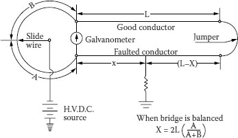
FIGURE 17.1 Murray Loop diagram. Underground Systems Reference Book, 1957.
A bridge circuit that has its best application on three-phase circuits consisting of three-conductor paper-insulated cables in a lead sheath. The reason for this is because it is a bridge circuit that requires a good conductor of the same length and size as the faulted conductor. In these types of circuits, the most common failure is on one of the phase conductors. Since the fault itself is part of the bridge circuit, an operator knows if it is going to work by noting the ability to pass a small current through the fault itself. One technique is to reduce the resistance of the failure to the shield or ground by passing a higher current through the fault prior to using the Murray Loop bridge circuit. The bridge circuit normally can be used with a low voltage direct current source; however, if the lower voltage is insufficient to pass current through the fault, a higher level of voltage can be applied. This assumes that the bridges, as well as the connections, are capable of withstanding the higher voltage. The Murray Loop can be used to find approximate locations on cables that are of shielded or nonshielded design. Accurate records of conductor length and size are a must; if known, this method can give very accurate results (Figure 17.1) [2].
17.3 UNDERGROUND RESIDENTIAL DISTRIBUTION
In the US around 1950, direct buried cable installations were used to a great extent in new residential areas. This type of installation was less obtrusive to the eye and both economical and faster to install. After several years, failures occurred on these installations. Cables were found to have inherent problems because of the various applications and field environments to which they were exposed. Consequently, the need for accurate fault locating equipment became a prime requirement. Since the cables were direct-buried, the ability to remove a section of cable was eliminated. It was now necessary to locate the failures within the area that a crew could dig and find the failure. This was not as easy as it sounds. Not only was the equipment needed, but also the men must be trained and able to operate the instruments and accurately locate failures. The process was compounded since there were different designs of both secondary and medium voltage cables. Secondary cables were usually without an insulation shield while the medium voltage cables were of a shielded design. Both of these cable designs required different approaches and techniques to adequately locate the precise area to dig for the failure.
The use of the Murray Loop became impractical mainly because the majority of the residential circuits were single phase. In addition, accurate lengths of cable are required with a bridge circuit and these were not available in the residential direct-buried cable systems. The capacitor discharge system became very useful in accurately locating buried failures. In fact, this system became one of the most widely used instruments by many companies. Many of the engineers that had served in the war used their experience with military equipment and applied it to cable fault locating. The equipment they modified was the radar system. Modified to connect to a cable or overhead line, these sets were the first attempts to utilize the theory. They were not accurate and were very complicated to the point that an engineer was needed to properly adjust the various settings.
17.4 METHODS OF LOCATING FAILURES
The following are methods of finding failures on underground cable systems. The success of some of these methods is often dependent on the type of system on which it is used, or the skill of an individual operator. You may find that the name used to refer to these methods may change from one company to another, so it is necessary to refer to the basic concepts when investigating new equipment [3].
Location of the cable route is the most important part of fault finding on a direct-buried system. Once the faulted cable has been identified, the next step is to verify the route. Unlike a conduit system where accurate locations are maintained for conduit runs, manholes, and terminations, the direct-buried system does not have a specific route. Installation problems in the field may cause the construction crew to change the route. These changes are very seldom noted in the original installation drawings. Splices may be installed as part of the initial installation or added when repairs are made on a previous failure. In some cases, extra cable may be buried with the intent of extending the circuit for future loads to be added, or for situations where the cable route is changed to go around unknown objects buried in the ground.
This method of isolating the failure was originally used when no other instrument was available. Now seldom used, it has an application where cable length exceeds the capability of available instruments. Long, buried cables can be cut in the center of that length and then tested both ways to see which half has the failure. The resulting length of cable to be tested is now reduced by 50%. This method can be repeated until a short section of cable is known to contain the failure and is within the capability of the available instruments. “Cut and try” should only be used when other methods are not available since it may damage otherwise serviceable facilities.
17.4.3 RADAR OR TIME DOMAIN REFLECTOMETRY
Shortly after World War II, radar or TDR sets became available on the surplus market. People who had used the radar sets during the war used their experience to modify these sets for use by underground personnel to find failures on underground cables. At first, these sets were cumbersome to use and fairly complicated to adjust. Like many new instruments, improvements have been made through the years. For the people performing fault locating, radar is becoming the instrument of choice. Radar sets send out a pulse of relative low voltage which is reflected back to the set itself when it encounters a change of impedance. The extremes of the change of impedance are the open end of a cable and a short between the conductor and the ground shield. The trace on a screen is a measure of time for the pulse to travel to the failure and back. It is necessary to know the velocity of propagation of a pulse for the type of cable involved and the length of the cable being evaluated, as this length is the length of the trace on the radar instrument. Application of this equipment is restricted to a shielded cable design in which the characteristic impedance is fairly constant throughout the length.
The TDR pulse travels along the cable system at a velocity that is a fraction of the speed of light. Depending on the insulation on the cable, this speed is in the order of 50% to 70% of the speed of light.
17.4.4 CAPACITOR DISCHARGE (THUMPER) SET
The capacitor discharge instrument has been nicknamed “Thumper” because of the audible sound it makes when the energy of the capacitor discharge occurs at the failure in the ground. It was originally used for duct and manhole systems but it is this thumping sound that made it one of the most useful devices for exactly locating the failure in direct buried systems. The capacitor discharge consists of three basic components. A high voltage, direct current power supply; a high voltage capacitor; and a timing device to control the times the charged capacitor is connected to the faulted cable. The timing device may be an adjustable spark gap or a set of contacts that are controlled by a timing device. This instrument requires that the discharge from the capacitor occurs between the phase conductor and a shield or nearby ground. Therefore, it is mostly suited for shielded cable designs.
Experience demonstrated that if the thumper was frequently used over too great a time period, damage to extruded dielectric cable systems ensued [1]. By combining the TDR with the thumper, a fault can be pinpointed with only one or two thumps—thus minimizing possible damage to the system.
Figure 17.2 shows a fault-locating instrument suitable for field application that combines the TDR and thumper. The instrument consists of two testing features. It contains a high-voltage direct current circuit used to energize the capacitor discharge circuit and a TDR that locates the distance to the fault. The locating team can then turn off the set until one member can measure off that distance and wait for another thump to pinpoint the location.
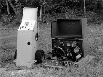
FIGURE 17.2 Combination thumper and TDR equipment. Photograph courtesy of Von Corporation.
Here are a few of the major improvements that have been made through the years:
• Controls have become simplified so as to become user-friendly.
• Screen traces have become more visible in bright light.
• Comparative traces are available for the purpose of comparing a good circuit with a faulted circuit.
• Velocity of propagation has been narrowed so as to make fewer choices for various cable constructions. It is still necessary to have an idea about what it should be as it effects the accurate distance to the failure. [See Chapter 20 for a discussion of Velocity of Propagation.]
• Taking TDR readings from both ends of a cable improves the accuracy of the measurement.
• Introduction of an electrical discharge at the failure will show the fault location by breaking down the failure and capturing it on the viewing screen.
The earth gradient instruments are used on nonshielded cables by applying a signal to the phase conductor of the faulted cable and a return path to a ground connection. The signal travels through the ground returning to the ground connection at the transmitting instrument. The returning signal can be detected above the ground in close proximity of the buried cable with a sensitive meter.
Transmitters normally consist of a direct current signal of sufficient voltage to supply a detectable signal with probes on the surface of the ground. Direct current signal is preferred where there is a chance of stray alternating currents in the vicinity of the faulted cable.
Detectors used with the direct current transmitter consist of: microammeters with a zero center feature; a control for the sensitivity; and a set of probes, which either can be frame mounted or used separately.
Used mostly on direct buried nonshielded cable normally used for secondary main and service cables, this method has an excellent record for finding failures on aluminum conductor cables where the aluminum conductor has corroded. During the corrosion process at the failure, the aluminum powder expands, causing the insulation to break (if it not already broken) and make a connection to ground. This is where the earth gradient starts.
17.4.6 CAPACITANCE MEASUREMENTS
This method of fault location can best be used on cables where the failure consists of an open circuit of the phase conductor.
A shielded cable has fairly uniform capacitance between the phase conductor and the insulation shield. By knowing the capacitance per foot of the cable, an approximate location of an open-type failure can be calculated. If the capacitance per foot is not known, an alternate method consists of measuring capacitance from both ends of the faulted cable. A ratio of the two readings will provide an approximate location as long as the cable is uniform throughout the run under test (Table 17.1).
17.4.7 INSTRUMENTS INFREQUENTLY USED IN NORTH AMERICA
The following are methods of fault locating on underground systems that have been used by some fault-locating personnel. They are listed here only for reference and not as a recommendation of widely used practices in the US today. Some of the methods listed here are similar if not identical to others in the list, but have been given different names by users depending on which reference material you are using as a guide:
• Murray/Fisher Loop
• Varley Loop
• Hilborn Loop
• Insulation resistance
• Pulse decay
TABLE 17.1
Capacitance of 175 mil 15 kV Cable
Condutor Size |
Insulation Type |
Length in Feet |
Capacitance Value in Microfarad (μF) |
#2 AWG |
EPR |
500 |
0.04 |
#2 AWG |
XLPE or TR-XLPE |
1,000 |
0.06 |
4/0 AWG |
EPR |
1,000 |
0.10 |
1,000 kcmil |
EPR |
1,000 |
0.19 |
• Differential decay method
• Standing wave
• Charging current
• Impulse current differential method
17.5 FAULTED CIRCUIT INDICATORS
Faulted circuit indicators (normally referred to as “fault indicators”) do not provide a location of the fault on a circuit, but do reduce the area in which the fault-locating equipment can be applied. This is extremely important when locating failures on long lengths of cable. It is also a valuable tool when locating faults that are installed in areas where there is limited access for the personnel performing the fault locating.
Fault indicators of the type addressed here can be obtained to cover a range of currents depending on the type of circuit to which they are attached. It is important to know what the normal current is in the circuit, and in addition, intermittent increases in current, which may occur on the circuit. Knowing these two factors will minimize the occurrence of a false tripping of the device. The effect of the exact fault current minimizes range-faulted indicators, which will automatically reset when the circuit is energized.
Early applications had limited success in many areas due to the following reasons:
1. Initial fault indicators were of the manual reset type (see Figure 17.3) that required the operating departments return to the previously faulted cable circuit, access each location where they were installed, and manually reset the device. An external tool is required to reset this indicator.
2. Information on the correct placement of the fault indicators was often not available to the installer. Consequently, they were installed on the cable in such a location where they did not work properly. When properly installed and reset after every failure on the circuit, these devices provided a valuable service to the people locating faults.
Fault indicators are designed so that they detect a given level of current passing through the cable to which they are connected. On alternating current circuits, the indicators do not show which direction the fault current is flowing—only that the current has exceeded the rated current of the indicating device. It is necessary for the user to inspect the fault indicators starting at the source of the current into the circuit. This continues until the user finds one indicator that had not experienced the fault current. The user then knows that the circuit failure is between the fault indicator, which showed excessive current, and the one that did not show excessive current (no target).
Magnetic fault indicators are placed over a conductor and detect the magnetic field caused by electric current flowing in the conductor. When the current exceeds the rating of the fault indicator, a warning will appear on the device, as a target, light, or noise showing that current much greater than normal (fault current) has passed through the fault indicator.
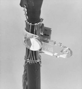
FIGURE 17.3 Manual reset fault indicator. Photograph courtesy of E.O. Schweitzer Mfg. Co.
An improvement over the manual reset fault indicator consists of an operating button, which eliminates the need for a separate tool to reset the indicator. It also eliminates the requirement of removing the fault indicator from the circuit as is required in Figure 17.4.
The automatic reset feature shown in Figure 17.5 is one of the most important features to the utility operating department. It was no longer necessary to return to the circuit that had been faulted and repaired, access every fault indicator, and reset the device manually. These indicators are designed so as to take a sampling of current from the repaired and energized line and use that to reset the fault indicator. In other words, all fault indicators return to a no fault indication.
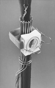
FIGURE 17.4 Fault indicator designed with a reset button. Photograph courtesy of E.O. Schweitzer Mfg. Co.
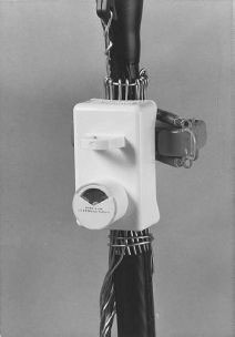
FIGURE 17.5 Fault indicator with automatic reset. Photograph courtesy of E.O. Schweitzer Mfg. Co.
Figure 17.6 shows a fault indicator with a remote target attachment. This allows operating personnel access to the indicator without entering the transformer or switchgear. It is sometimes used in substations on outgoing circuit for a quick evaluation of which phase is in trouble. One of these must be attached to each phase.
Figure 17.7 shows a fault indicator mounted on the voltage test point on a separable connector. The voltage test point was initially developed for the purpose of testing the line or energization without removing the elbow. However, now adapting the fault indicator to the test point has expanded its usefulness.
The voltage test point is available for purchase to those customers who choose to use it. If you have, or plan to buy, this feature when purchasing separable connectors and if you desire to use this type of fault indicator, you will need to specify this at the time of purchase. At present, there is not a standard for the physical size of the voltage test point. Therefore, when using this feature make sure that the fault indicator fits the voltage test point for which it is intended. The separable connector fault indicator uses the energy from the energized circuit through the voltage test point to reset the indicator after the circuit is returned to service. Previous indicators used current, or the mechanical push button, to reset the indicator. This fault indicator has the advantage of not being able to be installed incorrectly as it can only be used with a voltage test point.
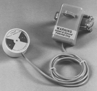
FIGURE 17.6 Fault indicator with remote target. Photograph Courtesy of E.O. Schweitzer Mfg. Co.
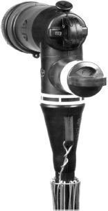
FIGURE 17.7 Separable connector with fault indicator mounted on test point. Photograph courtesy of E.O. Schweitzer Mfg. Co.
Figure 17.8 shows an application for a fault indicator on overhead circuits. This one utilizes the energy from the voltage in the conductor to reset the target. While the reset feature is an advantage for underground applications, one major advantage of the manual reset fault indicator on overhead applications is the fact that the indicator does not reset.
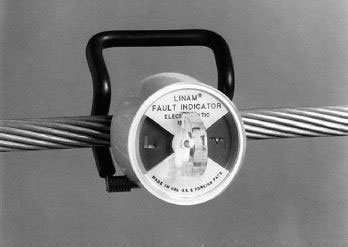
FIGURE 17.8 Fault indicator for overhead application. Photograph courtesy of E.O. Schweitzer Mfg. Co.
This means that a circuit that experiences intermittent faults would normally be difficult to find. However, since the manual fault indicator does not reset, operating personnel can return to the previously faulted circuit and examine the fault indicators to locate the previous intermittent failure.
1. Hartlein, R. A., Harper, V. S. and Ng, H., April 1994, “Effects of Voltage Surges on Extruded Dielectric Cable Life,” IEEE Transactions on Power Delivery, Vol. 9, pp. 611–619, EPRI Project RP-2284.
2. Underground Systems Reference Book, 1957, Edison Electric Institute, Publication #55–16, New York, NY.
3. Underground Cable Fault Location Reference Manual, November 1995, EPRI TR-105502.