
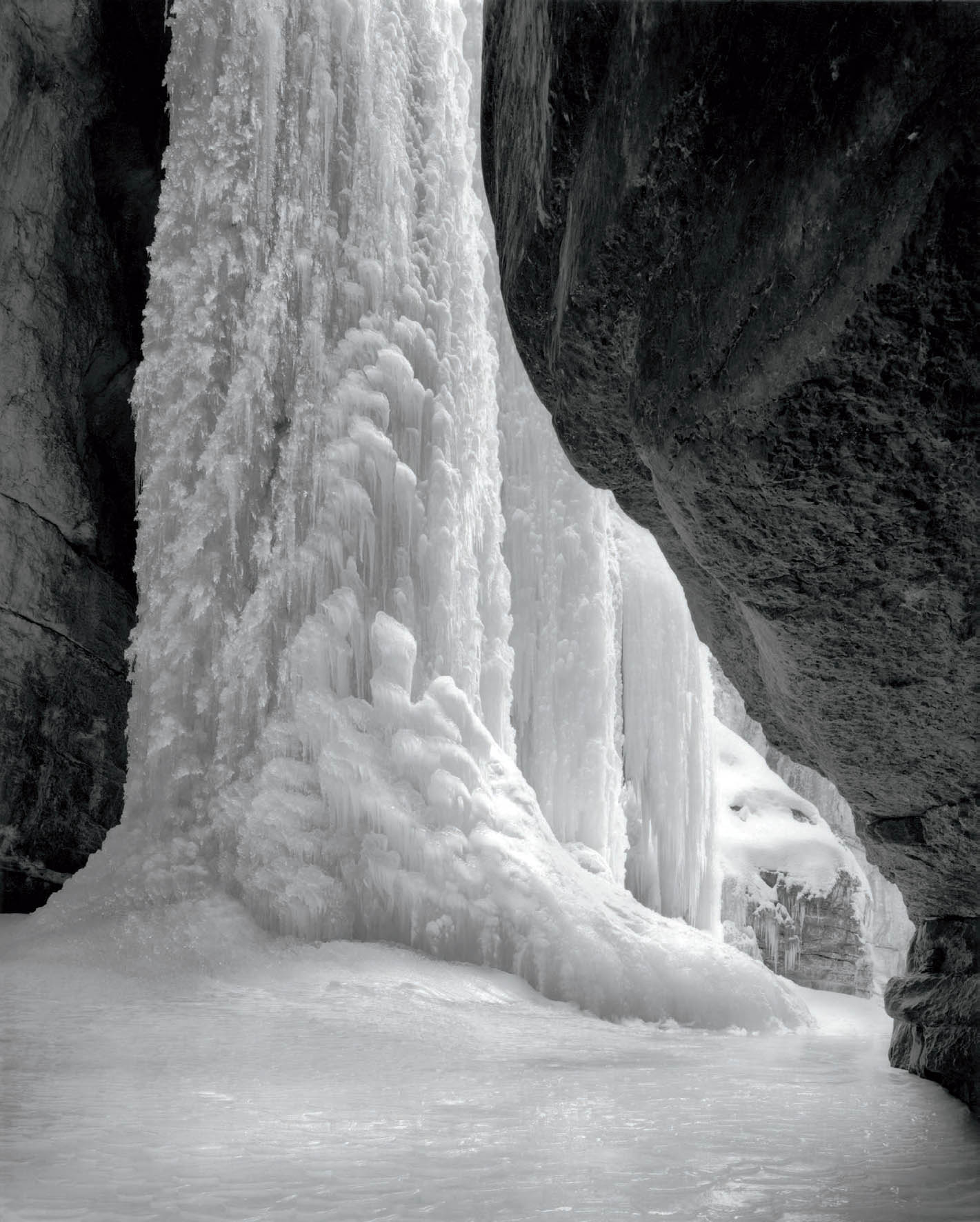
Figure 9-1: The Queen of Maligne
Maligne Canyon (pronounced Ma-leen) in Jasper National Park is inaccessible in the spring, summer, and autumn, as a powerful river scours the deeply cut limestone chasm. But in winter the river freezes, allowing access. At one location within the 180-foot deep canyon an underground seep hits the canyon wall just below the rim. As water runs down the inner canyon wall, it freezes, creating the enormous natural ice sculpture known as the Queen of Maligne.
Although the limestone walls are light gray, the contrast between the walls deep in the canyon and the icefall in a more open section is immense, requiring compensating development of the negative to hold the brightness range within printable densities. The means to accomplish this is simple in traditional film photography.
CHAPTER 9
Contrast Control and the Extended Zone System for Black-and-White Negatives
![]()
ANSEL ADAMS ONCE LIKENED PHOTOGRAPHY TO MUSIC with his famous analogy, “The negative is the score; the print is the performance.” The composer creates the score, including everything he or she wants; then a performer interprets the score as he or she sees fit. In photography, you are both the composer and the performer. This chapter gives you the tools to make the score far richer than you may have imagined possible. Chapter 10 extends that thinking into the realm of the performance.
Chapter 9 Overview
Chapter 8 deals with proper exposure of the black-and-white negative; this chapter deals with developing it to the level of contrast you want, thus giving you immense control over your imagery.
The zone system can be used not only for placing an object into any desired tonality, but also for changing contrast between objects. Since there is more than one object (or tonality) in any photograph, the moment you place one of them at the density you desire, the others automatically land as far away in density as the light meter shows. That may be either too close in density to the first object or too far away. There is no assurance that exposing one object at the appropriate density places the others at a desirable density for printing purposes. You may wish to have the other objects brighter or darker. In other words, you may wish to alter the level of contrast between the objects.
By varying the length of time for negative development, contrast can be increased or decreased in the black-and-white negative. Lower zones of the negative (the thinnest or least dense portions, which become the darker portions of the print) develop fully within a few minutes, then change little with extended development times. This tells you that the low zones (referred to as the scene’s “shadow area”) are determined almost exclusively by negative exposure, with little change occurring as a result of negative development.
The middle zones (roughly Zones 4, 5, 6, and 7) can be altered by changes in negative development times, with each zone affected more than the previous zone. The higher zones (generally Zone 8 and higher) are greatly affected by changes in negative development times. The higher an object is placed on the zone scale at the time of exposure, the more it can be altered by changes in negative development.
This tells you how to “read” a negative. If your shadow areas show good density—appropriately low, but with good density separations between them—then your exposure was good. This is true because negative development has little effect on shadow areas; if they look good, it tells you that their exposure was on target. Low-density areas are almost purely determined by your initial exposure. Once you have those densities nailed down, look at your highlights. If your highlight densities are good, then your negative development is good. This is true because altering negative development has such a great effect on the higher zones.
If your shadow areas are too thin or nonexistent, simply increase your exposure. Don’t think about changing your development time because it will have little or no effect on the low zones.
Once you get sufficient exposure for the shadow areas to have good density separations, then look at the highlights. If they are too dense, reduce your development time; if they are too thin, increase your development time. But don’t change your exposure to compensate for the changes in development time because development changes do not materially affect the low zones.
The full range of the negative—Zone 0 to Zone 16–18—can then be put to use. This chapter is divided into three sections beginning with an explanation of what happens to the exposed negative when it is developed. The second section has examples of how to use that information for creative purposes. The last section examines the general characteristics of negative materials and developers, and the specifics of processing to make full use of the negative a reality.
The range of black-and-white film is astonishing, and the creative potential inherent in fully using the “extended zone system” (i.e., including the extremely useful zones above Zone 10 that most instructors ignore . . . or fail to recognize) is immense. As we saw in chapter 8 for exposure of the negative, the underlying concepts for negative development are simple. The approach here is nontechnical; though graphs are used in the explanation, they do not require mathematical sophistication on the part of the reader.
The Negative During Development
As explained in chapter 8, every part of a negative is sensitized to the amount of light that fell on it during the exposure. This sensitized negative is known as the latent image. At the time of exposure, the negative gains a potential for density, but no actual density. Only during development does it gain density.
When the exposed negative is put into the developer, all of its parts begin to develop—i.e., to grow denser than the unexposed film base—in proportion to the degree of sensitization. The areas sensitized to the greatest extent build density at a rapid rate; those sensitized to a lesser extent build density at a slower rate. Those areas sensitized to the lowest level, Zone 1, gain full density rapidly because there is so little to gain and they are developed in a minute or two. Additional development time has no real effect on Zone 1—except that extended development tends to progressively fog, or darken, the film base itself, making Zone 1 denser along with an equal density increase in all higher zones.
Areas sensitized above Zone 1 continue to grow in density as development continues. Once areas sensitized to Zone 2 reach that density, they gain slightly greater density with continued development—but they won’t even reach Zone 2½ without excessively long development times. Once areas sensitized to Zone 3 gain that density, they can be developed nearly up to Zone 4 with increased development times. Areas sensitized to Zone 4 can be pushed beyond Zone 5 in density with extended development times.
The amount of development time needed for each zone to reach its proper density is known as the “normal development time.” How do you determine “normal development time”? By finding out how long it takes to develop any exposed zone to that exact density. For example, normal development time is the time required to develop an area placed at Zone 5 (the gray meter reading) to Zone 5 density. At the start of development, the exposed (i.e., sensitized) Zone 5 area has no density, but as development proceeds, density increases. It quickly exceeds Zone 1, and then surpasses Zones 2, 3, and 4 before finally achieving Zone 5 density. That’s “normal development time” (for that combination of film and developer). If development continues beyond that point, the density will exceed Zone 6 and ultimately reach Zone 7.
But how do you identify true Zone 5 density? Let’s go back to the beginning of chapter 8 where we defined standard exposure as the minimum exposure under the enlarger to achieve maximum black for Zone 0. Once you find the standard exposure, place the Zone 5 negative in the enlarger (at the same height and aperture you used to determine the standard exposure) and give it that same exposure. If it’s true Zone 5 density, the print you get will be exactly the same tone as the 18 percent gray card. When you develop the Zone 5 negative for the appropriate amount of time to achieve that density, you have found the normal development time. (This fills in the temporary gap in the explanation of the zone system at the beginning of chapter 8. It may be worthwhile to reread those pages now.)
Each higher zone grows progressively denser with increased development time. The portion of the negative exposed at Zone 6 (one stop brighter than the gray meter reading) achieves Zone 6 density in the normal development time, but it can exceed Zone 8 density with greatly extended development time. Increasing the development time beyond normal does not simply shift the density of each zone equally; instead, it expands each zone in proportion to its original placement. This is crucial, for it tells you that increased development time increases contrast because it pushes the exposed zone placements further apart.
![]() Increasing the development time beyond normal does not simply shift the density of each zone equally; instead, it expands each zone in proportion to its original placement. This is crucial, for it tells you that increased development time increases contrast because it pushes the exposed zone placements further apart.
Increasing the development time beyond normal does not simply shift the density of each zone equally; instead, it expands each zone in proportion to its original placement. This is crucial, for it tells you that increased development time increases contrast because it pushes the exposed zone placements further apart.
If development is terminated before the normal development time, precisely the opposite effect occurs. In that case, the density of each zone decreases in proportion to the original exposure on the zone scale. The higher zones are reduced in density more than the lower zones. Zone 1 is fixed in density no matter what development the negative is given. Those areas exposed as Zone 2 will not quite reach full Zone 2 density in less than normal development time. Zone 3, however, will begin to show significant changes, perhaps dropping to Zone 2⅔ or 2¾. Areas exposed as Zone 4 may only reach Zone 3½ if development time is cut short. Zone 5, the gray meter’s average reading, may just exceed Zone 4, and Zone 6 may be just shy of Zone 5.
As you progress up the tonal scale to higher exposed densities, each is developed to a higher density than its predecessor, but each is reduced below normal density by a greater amount than its predecessor. Zone 9 may drop to Zone 7, while Zone 11 may barely exceed Zone 8 with a shortened development time.
The Bellows Analogy
A simple way to grasp the concept of progressively increased densities with extended development times, and progressively reduced densities with shortened development times, is to think of each successive zone as a number on the successive pleats of a camera bellows, or any type of bellows. When development begins, the bellows are crunched down completely and each zone placement has zero density. As development progresses, the bellows are slowly extended to the right from the fixed point on the left so that the pleats, or zones, separate from one another—meaning that they separate in density. The longer the development time, the further the bellows are extended to the right, and the greater the density of the higher zones up to maximum negative density (diagram 9.1).
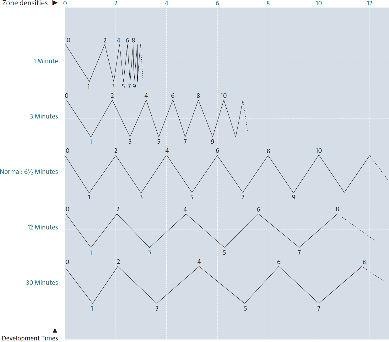
Diagram 9.1: Density Increase During Development Time—The Barnbaum Bellows Analogy
Negative density and print tonal scale. Please note that this diagram is not a model of actual negative densities during development, but rather a schematic of what happens to densities as development proceeds. I will refer to it in the following examples to be consistent within the text, but don’t expect your combination of negative and developer to yield the same results as those shown here. Yours should be close, but not exact. (See Time/Temperature Development Charts for several films in diagrams 9.6–9.9.)
Within the first minute of development, the zones begin to separate. At four minutes, Zone 1 is fully developed and Zone 2 is near its normal density, while the higher zones are noticeably falling short. If you choose 6½ minutes as the normal development time (my development time for Ilford HP5+ or Kodak Tri-X film in Kodak HC110 developer), you will see that the zone placements—the sensitization levels of the latent image, which are the numbers on the pleats—correspond to the developed densities. Beyond 6½ minutes, all zones except 0 and 1 continue to grow ever denser.
For example, note in the schematic representation at three minutes development time, the exposed Zone 4 reaches just above Zone 3 (a loss of nearly a full zone from its normal development density) whereas Zone 10 reaches only a bit above Zone 6, which is a loss of nearly 4 zones from normal. This shows that the higher zones lose more density than the lower zones with reduced development times. Contrast is decreased when development times are reduced below normal.
Conversely, with 12 minutes of development the exposed Zone 4 reaches 4⅔ density (a gain of ⅔ zone), whereas the exposed Zone 8 reaches almost Zone 11 (a gain of nearly 3 zones), and the exposed Zone 10 (beyond the chart) may go beyond Zone 14 (a gain of 4 zones). This shows that the higher zones gain more density than the lower zones with increased development times. Contrast is increased when development times extend beyond normal.
Another way of representing the development characteristics of the negative is via a graph (diagram 9.2), where the X-axis (the horizontal axis) represents development time in minutes and the Y-axis (the vertical axis) represents density. Each curved line represents the increase in density of an exposed zone as development proceeds. All exposed zones start the development process with no density, and density increases in proportion to the initial sensitization. At my normal development time of 6½ minutes, each exposed zone reaches its proper density. Beyond 6½ minutes, density continues to slowly increase (except for Zone 1) in proportion to the initial sensitization.
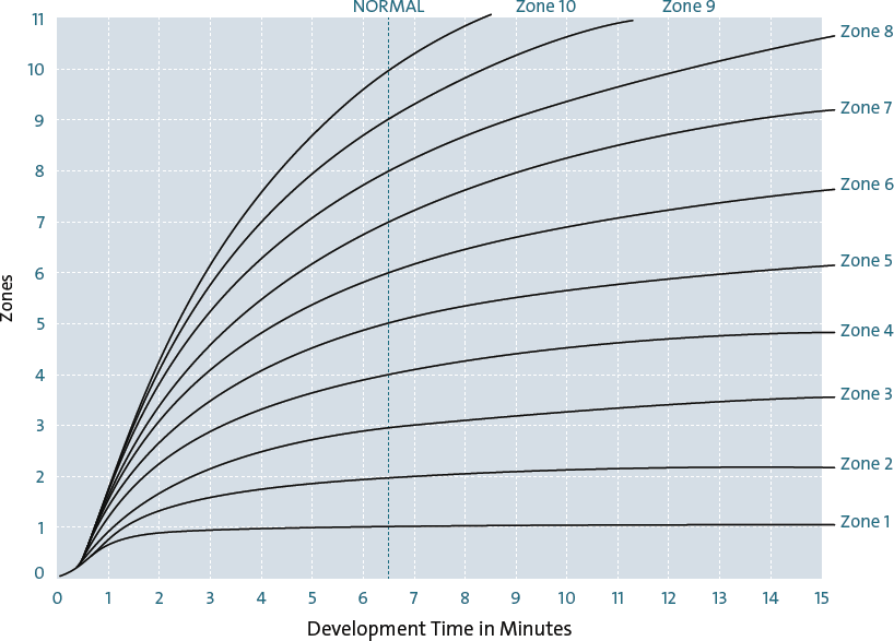
Diagram 9.2: Zone-by-Zone Negative Development Curves
Diagram 9.2, like the bellows schematic, is meant to be a visual aid to the understanding of the development process, but is not meant as an exact model of any specific negative material.
For those who have trouble understanding graphs, a brief explanation may help. Choose any one of the curved lines, such as the dark line, which represents Zone 5. It begins at the lower left, like all the other lines, because it has no density at the start of development (0 minutes). As you move to the right, which represents elapsed development time, the curve rises, representing increased density. When you stop at any point along the curve, the distance from the Y-axis (the left edge) represents elapsed development time, while the height above the X-axis (the bottom) represents density. In three minutes, for example, negative density barely surpasses Zone 3. In 6½ minutes (shown as normal development time in this graph), it exactly reaches Zone 5 density. In 12 minutes, it exceeds Zone 6 density. Follow any other line to see how development proceeds with time.
Looking at diagram 9.2, if you choose any length of development time along the X-axis, and then rise vertically along that time line, you will see how dense each exposed zone becomes during development. At 6½ minutes (normal development time on this graph), each exposed zone reaches its proper density. Below 6½ minutes, each exposed zone is proportionately below its normal density; above 6½ minutes, each zone is proportionately above its normal density (except Zone 1, which reaches its density quickly and stays there).
The initial jog in the curves prior to density build-up reflects the fact that the emulsion absorbs the developer before density begins to increase. This is the same phenomenon you see during printing, when the paper is placed in the developer and 10–15 seconds elapse before the image begins to appear. The process is somewhat slower for a negative, taking 15–20 seconds (maybe more) for density to manifest.
Putting Higher Zones to Work
Understanding negative development is very important, not only because it shows how contrast can be increased or decreased, but also because it indicates how to use the zones above Zone 9. As explained in chapter 8, in a normally developed straight print made on average contrast paper, all zones above Zone 9 print as blank white (chapter 8). For this reason, most photographers—and even many instructors—feel that the range of a negative is limited to Zone 0 through 9. Not true. Diagram 9.2 tells you that an object can be exposed in a higher zone and that reduced development can bring it back within printable range. Furthermore, if two objects are metered to be very far apart tonally—say, eight zones—they can be exposed at Zone 4 and 12 respectively; then they can be given greatly reduced development time, so that the darker object is developed to Zone 3 while the lighter object is reduced below Zone 9.
In chapter 10 we will see how areas developed above Zone 9 can still be printed. This will further increase your use of the higher zones and greatly expand your creative potential. In this manner, you can use the full range of the negative rather than limiting yourself to the lower half.
There are two points I wish to stress here. First, enlarging papers possess a much shorter range of tonalities than negative materials. So, while a negative is capable of recording scenes of excessive contrast within its extended range, its scale may need to be compressed to fit on the shorter tonal scale of the enlarging paper. Second, while the long tonal scale of the negative is fully usable during exposure, it is not wise to develop negatives to high densities (i.e., Zone 11 and up) because those densities require excessively long exposures under the enlarger to yield tonalities. Therefore, if you encounter a scene of excessive contrast and choose to expose the brightest areas well above Zone 9 (a perfectly good approach), be sure to use less-than-normal development times in order to avoid excessive densities. Good separations will still be maintained in your negative and in the print.
In fact, enlarging papers have the same long tonal scale that negatives possess, but the two are viewed differently. You view a negative with light coming from behind it toward your eye. You view a print by light coming from behind you, going through the emulsion, hitting the base of the enlarging paper behind the emulsion, and reflecting back through the emulsion once more to your eye. That’s why there is an apparently reduced tonal scale to the print. If, instead, you place a bright light behind a fully developed print, wet or dry, you will see details in the blacks that are invisible to the eye with the print viewed normally, showing that the enlarging paper’s tonal range does equal that of the negative. But this is merely fascinating information, since it has no practical application. We all view prints as described above, very rarely with a bright light source behind the print.
During exposure, the spread of zones between two objects never changes, but it can be altered during negative development. If two objects are metered to be 5 zones apart (i.e., 5 stops), they will always be 5 zones apart when exposed, unless they are altered by filtration or by reciprocity failure (explained below). Depending on the exposure you make, they can be placed at Zone 2 and 7, 3 and 8, 4 and 9, 5 and 10, etc., but they’re always five zones apart. The 5 zones of separation can be maintained by normal development; they can be brought closer together by developing the negative less than normal, known as “minus development”; or they can be separated further by developing the negative longer than normal, known as “plus development.”
Of the two ways that contrast can be altered during exposure—filtration or reciprocity failure—filtration is better known. Suppose two objects meter three zones apart, and the darker object is red while the lighter one is green. A red filter will lighten the red object with respect to the green one and therefore reduce the contrast between them at exposure. A green filter will darken the red object with respect to the green one and expand the contrast between them at exposure. Filtration must be taken into account when exposing and developing the negative.
Reciprocity Failure
Reciprocity denotes the way film responds to light within the standard range of exposures, from one second down to 1/1000 second. Within that range of exposure times, the negative maintains a reciprocal relationship between light level and exposure; if you cut the amount of light in half, you can double the exposure time to maintain the same overall image. (It’s a reciprocal relationship because it means that 2 × ½ = 1.) Thus, if your exposure is 1/30 second and you close the aperture from f/8 to f/11, increasing the shutter speed to 1/15 second will maintain the same overall exposure and image. Or, if your exposure is 1/30 second and the light level drops in half, expanding the shutter speed to 1/15 second will also maintain the same overall image.
![]() During exposure, the spread of zones between two objects never changes, but it can be altered during negative development.
During exposure, the spread of zones between two objects never changes, but it can be altered during negative development.
For times beyond one second (encountered under dim light conditions), this reciprocal relationship breaks down, leading to reciprocity failure. If, for example, you calculate your exposure to be five seconds at f/8, but you need greater depth-of-field and close the aperture to f/11, a 10-second exposure will not give you the same overall image. It turns out that you may need to keep the shutter open 15 seconds or more to gain the same overall exposure. The reason is that beyond one second, film becomes progressively less efficient in its ability to gather light. (This loss of efficiency varies from one film to another, so you’ll need to learn the characteristics of your film to know how to deal with it.)
During a long exposure, light reflected off brighter objects is accepted by the film somewhat more efficiently than light from dimmer objects. Therefore, overall contrast increases progressively during a long exposure as the exposure time increases. My experiences in the English cathedrals, where exposure times generally ranged between 3 and 20 minutes, and in the Arizona/Utah slit canyons, where some exposures exceeded an hour in length, and one was fully 3½ hours, show that the contrast increase due to lengthy exposures can be substantial (figure 9.2). Development must be altered by an appropriate amount in order to maintain the desired contrast.
Each of the sections in the tables below is labeled to indicate an approximate range of how much increase in contrast occurs as the result of a long exposure. Thus, when the increase is equivalent to an N+1 development, a development of N–1 is required to counteract it and yield overall normal development (see Time/Temperature Development Charts in diagrams 9.6 through 9.11).
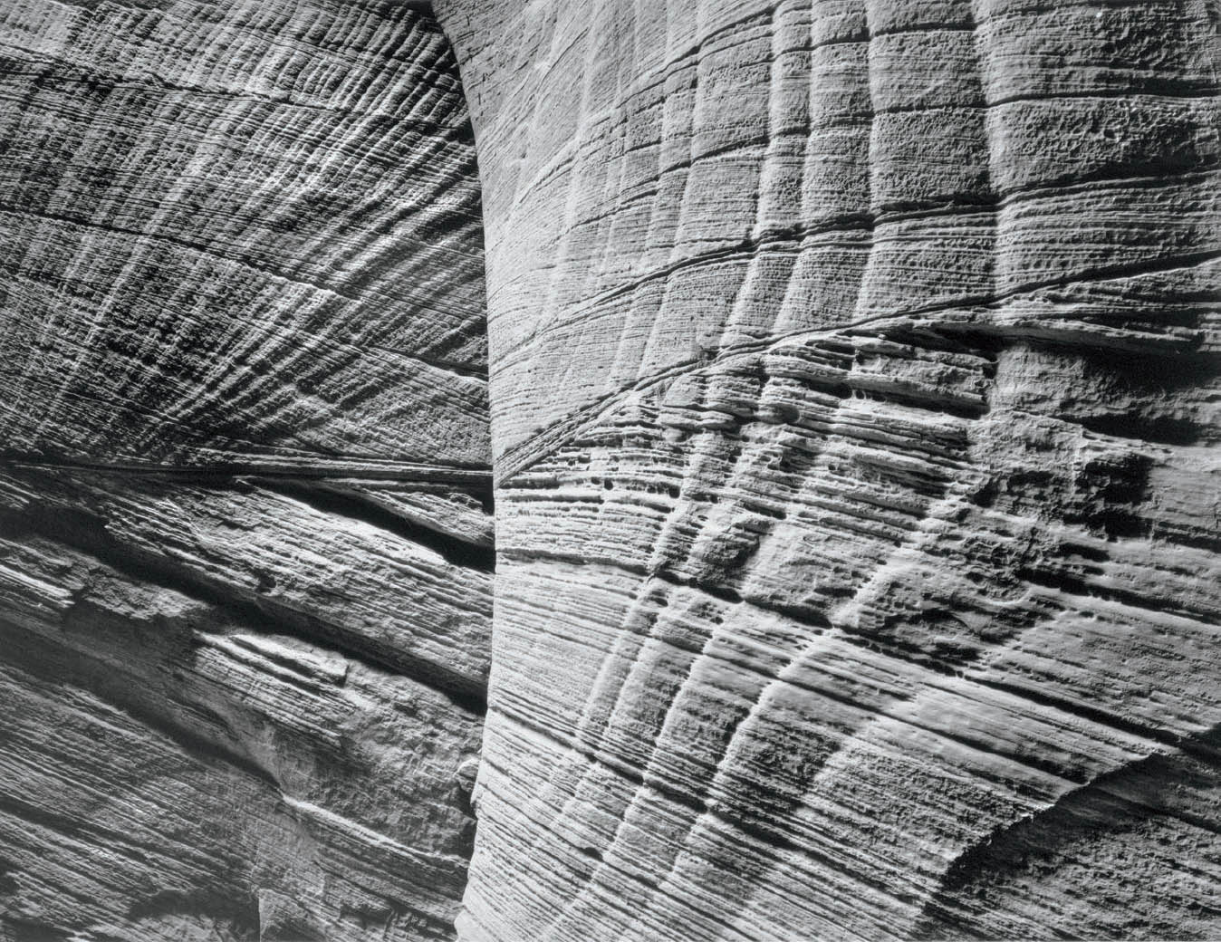
Figure 9-2: Buckskin Gulch, Two Walls
I was attracted to the relationship between the lines of the near wall (on the right), curving around a bend, to those of the more distant wall (on the left). Contrast was low, but so was the light level in the deep, narrow canyon. I used it to my advantage, stopping down to about f/45, and forcing a 20-minute exposure, which significantly increased contrast due to the effects of reciprocity failure.
Increased contrast due to reciprocity failure is a double-edged sword. If you want greater contrast in a scene, you get it automatically with longer exposures. You can force the situation in bright, flat light by using strong, neutral density filters to force long exposures that increase contrast. Furthermore, when you increase contrast via long exposures, it does not increase the film’s grain—whereas if you increase contrast via long development times, grain increases.
While reciprocity failure can be beneficial, my experience is generally that increased contrast from reciprocity failure most often occurs when overall light levels are dim. In most such situations, the contrast is already quite high. In both the English cathedrals and the slit canyons, reciprocity failure saddled me with undesirable additional contrast in situations that were already excessively contrasty. (All films vary in their reciprocity failure characteristics; some, like Fuji Acros or Kodak T-Max 400, have none up to two minutes of exposure.)
Another problem with long exposures is the fact that the gray meter does not calculate the film’s reduced response to low light levels. Within the negative’s normal response range you can determine your exposures as explained in this chapter and the previous one, but for long exposures (beyond one second) you must factor in additional time to compensate for reciprocity failure. Then you must alter contrast in negative development to compensate for the contrast increase during exposure.
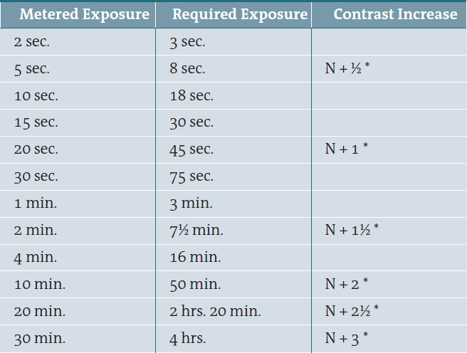
Diagram 9.3: Exposure Table for Reciprocity Failure of Tri-X Pan Film (ASA 320)
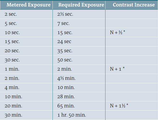
Diagram 9.4: Exposure Table for Reciprocity Failure of T-Max 100 Pan Film
In both tables (diagrams 9.3 and 9.4), the asterisk (*) indicates the approximate amount of contrast increase due to reciprocity failure and extended exposure. Thus, if you use Tri-X film and have a metered reading of 30 seconds, the table indicates that you must expose the negative for 75 seconds. But normal development of that negative will increase the contrast as if you had N+1 development (diagrams 9.6–9.9), so you must give the negative an N–1 to compensate for the contrast increase during the long exposure.
The reciprocity failure tables (diagrams 9.3 and 9.4) show the approximate exposure increase needed for extended exposures for both Tri-X and T-Max 100 films. The Tri-X table is my own personal table derived from years of practical experience (identical to Minor White’s own determination 40 years earlier). Kodak’s table for Tri-X is wildly incorrect. The T-Max table is based upon Kodak’s numbers, which are correct but incomplete.
It’s easy to interpolate between the stated times. The following example for Tri-X illustrates the proper method for using the table with the zone system. Suppose you want to place an object in Zone 7, and your gray meter gives you a five-second exposure reading. Of course, the reading places the object in Zone 5 (as always!), so first you double the exposure to 10 seconds in order to place it in Zone 6. Then you double the shutter speed to 20 seconds to place it in Zone 7. By consulting the reciprocity failure table, you determine that 20-second metering requires a 45-second exposure for Tri-X film.
Examples of Decreasing and Increasing Contrast
As a first example, let’s return to the sunlit snowfield of chapter 8. As before, you see the modulations of the snow, its hills and valleys. You want to photograph it so that those delicate tones are visible in the print. If nothing but snow is in the scene, it’s easy. All you have to do is decide where to place the snow on the scale and shoot. My choice would be an average placement of Zone 7½ or 8, which would yield a range of light tones from pure white to light gray and would show the modulations.
But suppose a large, dark boulder sits in the center of the field, oriented in such a manner that it’s shaded. Let’s agree that the rock should be about a Zone 3 tonality, and that the snow should still be placed at about Zone 7½ or 8 on the average. Suppose the gray meter gives a reading on the snow of f/16 @ 1/250 second, while the reading on the rock is f/5.6 @ 1/60 second. How many zones separate the snow and the rock? The separation is determined by adding the differences between the two readings in both aperture and shutter speed. F/16 represents 3 stops less exposure than f/5.6 as follows: f/5.6—f/8—f/11—f/16. At the same time, 1/250 second represents 2 stops less exposure than 1/60 second as follows: 1/60—1/125—1/250.
The difference is 5 stops, or 5 zones. No matter how you expose the negative, there will be a 5-zone spread between the snow and rock, which cannot be changed in the exposure. It may not be wise to expose at either the metered reading on the snow or the rock; if you choose the former, the snow would come out at Zone 5 and the rock at Zone 0, while if you choose the latter, the rock would be exposed at Zone 5 and the snow at Zone 10. But you know how to place the rock at Zone 3: close down stops from the gray meter’s reading on the rock. With the rock in Zone 3, the snow is automatically placed at Zone 8 on the exposure scale, and normal development brings the density of each to the desired level. (Further on I explain why I actually prefer the shadow placement to be in Zone 4 rather than Zone 3.)
Suppose, however, that the meter reading on the rock is f/4 @ 1/60 second rather than f/5.6 @ 1/60 second. Now the spread between the rock and snow is 6 zones, so that exposing the rock in Zone 3 automatically places the snow in Zone 9—too high for any texture. But since cutting the development time lowers contrast, if you place the rock in Zone 3 (which automatically places the snow in Zone 9) and develop less than normally, the higher zone drops significantly more than the lower zone. By cutting the time so that the Zone 9 exposure drops to Zone 8 (perhaps about six minutes, based on diagram 9.2), the Zone 3 exposure hardly drops at all. At most, it will drop to something above Zone 2¾. By exposing just a little higher on the scale, say Zone 3½ on the rock and 9½ on the snow, and cutting the development time a bit more, the snow can be developed to a density of Zone 8 (a drop of 1½ zones from the exposure) while the rock will drop less than ½ a zone to a point just above Zone 3. Now the spread of zones between the two objects is just what you wanted. You have achieved the precise contrast and tonalities you sought by thoughtful use of the zone system coupled with your knowledge of negative development.
Let’s play with this example just a little further. Suppose you decide that the dark (Zone 3) mass of rock in the midst of the light snow is too heavy, and you want the rock lighter. First, give the negative additional exposure, placing the rock in Zone 5, which automatically places the snow in Zone 11, given the zone spread between the two. Now, cut the development time substantially, perhaps to 4½ minutes based on the schematic. The Zone 11 exposure now is developed to a Zone 8 density, while the Zone 5 exposure ends up with a density of about 4¼. The spread of zones in the field is reduced to only 3¾ zones via clever exposure and development. The snow is the same density as before, but the rock is now 1¼ zones lighter, just what you wanted.
Both the snow and the rock are easily printable, yet notice how high your exposure placed the snow initially in Zone 11! That’s 2 full zones beyond the range of the paper in a straight print, yet well within the limits of tonal separations of the negative and thus a fully usable zone. In this case, you then reduced development to bring the final density down within the range of enlarging papers. In chapter 10, you’ll learn that even denser zones can be used in printing. The important point is that you shouldn’t limit yourself to exposures within the Zone 1 to Zone 9 range. Overcome your fear of putting the higher zones to use.
From this example, you can see how the common rule of “overexpose and underdevelop” has become accepted. If you want to cut contrast, start with extra exposure because density is lost in less-than-normal development. Without the extra exposure initially, you can lose valuable tonalities and textures in the lower zones.
Please note in the examples above that the decision of how to expose the negative is based on your initial determination of the tones you want in the final print (i.e., the end point, as noted in chapter 8). Then readings are made with the gray meter to determine the spread of tonalities (the starting point). Finally, exposure and development are simultaneously determined in order to arrive at the desired contrast level and overall placement for the negative.
Before going on to an example of expanded contrast, let’s see what would have happened if you took an average meter reading at the scene described above and used it without thinking further. The snow would dominate the scene, while the rock would be a relatively small part of it. Therefore, the snowfield’s reading would dominate the gray meter, and the overall reading of the scene (including the rock) would be only slightly lower than that of the snow without the rock. Suppose this overall reading was f/11 @ 1/250 second, or one full stop below the reading of the snow alone (it probably would not drop that much). If we used that exposure and developed normally, the snow would have a Zone 6 density and would print as a medium light gray. That would be a rather dingy rendering of snow. The rock, 6 zones lower, would be exposed as Zone 0. You would end up with a featureless black blob in a medium light gray morass. Obviously, that would be a disaster! That should demonstrate the value of the zone system and the importance of learning it thoroughly!
Now let’s turn to an example of expanded contrast. Suppose you are in a forest on a cloudy day and you see a leafy bush next to the base of a Douglas fir tree. The scene is beautiful, but the contrast is low. The gray meter reads the dark furrows of the bark at f/4 @ 1/15 second and the green leaves at f/5.6 @ 1/30 second. There is only a difference of 2 stops between the two readings, and averaging them would place the bark in Zone 4 and the leaves in Zone 6—a bit dull for me.
If you place the leaves in Zone 5 (i.e., expose the negative at the meter reading on the leaves), the bark would be exposed at Zone 3. Now you can give the negative substantially increased development. According to diagram 9.2, developing it for 15 minutes (roughly 2½ times normal) would raise Zone 3 to about Zone 3⅓ and Zone 5 to just above Zone 6⅓, increasing the spread between the leaves and bark about 1 zone. If you want still more contrast, you can print using high-contrast paper.
I don’t recommend adhering to the “underexpose and overdevelop” rule for increasing contrast. Underexposure severely limits your ability to increase contrast because the lower zones move very little during extended negative development. That is evident from diagram 9.2. The lower you place them in your exposure, the less you can separate them during development. For example, if you place the bark and bush at Zone 2 and 4 respectively, the same 15 minutes of development would raise the density of the bark to just barely above Zone 2, while the Zone 4 placement would increase to just above Zone 4½. Thus, the underexposure would limit the increase in contrast to ½ zone.
![]() I don’t recommend adhering to the “underexpose and overdevelop” rule for increasing contrast. Underexposure severely limits your ability to increase contrast because the lower zones move very little during extended negative development.
I don’t recommend adhering to the “underexpose and overdevelop” rule for increasing contrast. Underexposure severely limits your ability to increase contrast because the lower zones move very little during extended negative development.
However, if you expose the leaves at Zone 6 instead of Zone 5 (and therefore the bark at Zone 4 instead of Zone 3), the 15 minutes of development would raise the leaves to Zone 8 and the bark to Zone 4¾. Here, you have increased the tonal spread by almost 1¼ zones. If you exposed one zone higher, at Zone 7 and 5 respectively, the increased development time would raise the leaves to about Zone 10 and the bark to Zone 6¼, a 1¾ zone increase in contrast. Thus, the higher the initial exposure, the greater the contrast expansion through development (within reasonable limits, of course).
There are some trade-offs with this approach, to be sure. First, the negative may be quite dense, and therefore requires long exposures in the darkroom to achieve appropriate print tonalities. Second, the graininess of the negative increases with density, but this is generally an issue of minor concern. While these drawbacks must be considered, contrast has increased twice as much as with the “underexpose and overdevelop” approach. It should be noted that some of Edward Weston’s most famous negatives are so dense by today’s standards that they almost can be used for viewing solar eclipses! Yet they obviously produced iconic prints. I think too much emphasis today is placed on producing the thinnest usable negatives, and I see little merit to that approach.
My normal contrast negatives aren’t so dense that they’re bulletproof, but they certainly aren’t thin. If I want to greatly increase contrast, I expose at mid-densities and then overdevelop. I get a dense negative, but I also increase contrast substantially. As for the graininess, it shows up only in areas of smooth tonality, such as clouds or sky or smooth skin, but not in areas of sharp modulation, such as the hypothetical tree trunk example above. I do consider whether grain will be a factor in the final print, but it’s rarely a real problem. For small or medium format roll film, increased grain and density are greater problems than with larger negatives; but all things considered, I would always prefer having increased grain over a negative lacking in sufficient contrast.
The Exposure/Density Curve and Zone 4 Shadow Placement
The most important reason to avoid thin negatives is based on the separation of tonalities in the developed negative. Zone 1 is very thin with easily perceptible density above Zone 0. Yet translated to the print, both zones appear black with no real separation of tone between them. Zone 2 shows separation from Zone 1 in the print; in fact, on the negative there is a greater density spread between Zone 2 and Zone 1 than there is between Zone 1 and Zone 0. Higher zones show even greater separation of density. Diagram 9.5 shows a common graph known as the Exposure/Density Curve, which depicts how it all works. (For the mathematically inclined, this curve is the first half of a sine wave.)
In diagram 9.5, the X-axis (the horizontal axis) represents equal increases in exposure; the Y-axis (the vertical axis) represents increases in negative density with development. The continuous line represents normal development of a typical negative. The dotted line to its left represents the curve if development time is increased; the dotted line to the right represents the curve if development time is decreased. As the curve starts from Zone 0 it rises very slowly to Zone 1, being nearly horizontal in that area. Its height above the X-axis at Zone 1 represents its very slight density. It then begins to curve upward between Zones 1 and 2, representing the greater density spread between those zones. It curves even more steeply upward between Zones 2 and 3, again representing more density spread between those two zones.
From Zone 3 upward to the mid-teens, the curve is relatively straight, indicating nearly equal separations in density between zones. Above Zone 15, the curve flattens out again, representing decreasing separations in density between zones in the densest portion of the negative. The lower portion of the curve, where separations are minimal (Zone 0 to 2½) is called the “toe” of the curve. The upper portion of the curve, where separations are again minimal, is known as the “shoulder” of the curve. The large middle portion, where separations are greatest, is the “straight-line portion” of the curve. The straight-line portion is the best part of the curve—the part where you want your densities to be—because it’s where you get the most visible separations of tonalities in the print.
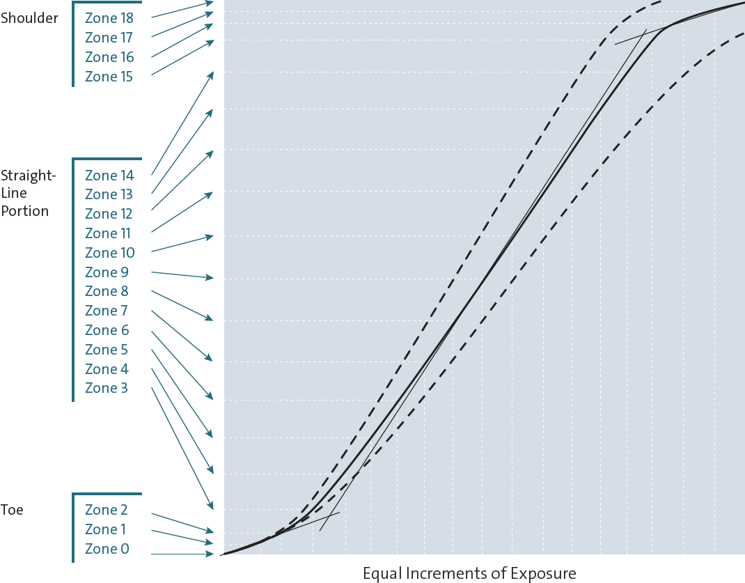
Diagram 9.5: The exposure/density curve
I strongly urge you to keep all of your exposures within the straight-line portion of the curve in order to maximize tonal separations as I do. You can do this by “overexposing” your black-and-white negatives one full stop. In this way, your Zone 1 is actually Zone 2. More importantly, your Zone 3 is now Zone 4. Good, dark shadow detail and texture are often printed at Zone 3 tonalities, but Zone 3 placement puts a portion of that texture on the toe of the curve, whereas Zone 4 placement puts it all on the straight-line portion of the curve, maintaining better separations. (Later, when printing the negative, give it extra exposure to bring the tone back to Zone 3.) You won’t lose anything with this approach, because the valuable part of the curve for virtually all black-and-white films ranges all the way up to Zone 15 before starting to flatten out again. I don’t consider this to be “overexposure,” but proper exposure for the best possible negatives. At the upper end of the scale, it’s wise to avoid exposures above Zone 15, where highlight detail may lose separation.
If you follow this approach, your negatives will tend to be a bit denser and require a bit more exposure time under the enlarger, but they will give your prints visible separations down to the deepest tones. There will be no muddying of dark tonalities above pure black.
For those doing digital photography, this recommendation is quite similar to the recommendation of exposing your digital images as far to the right of the histogram as possible without “clipping” (i.e., overexposing beyond the right edge of the histogram), as will be discussed in chapters 11 and 12. Digitally, this maximizes the information packed into your exposure, even though the image appears overexposed and “washed out” on your camera’s monitor. Later, in post-processing, you reduce the exposure to the tonalities you want, but it’s a smoother image with far less “noise” in the shadow areas. Thus, the traditional and the digital approaches dovetail in ways that most photographers do not realize.
My method of proper film exposure is simple: cut the film’s recommended ASA (the rated film speed—the faster the film, the higher the number) approximately in half, which is the equivalent of opening up one stop, then do everything else as discussed above. If you use the DIN number instead of the ASA, drop the number by one. With Tri-X sheet film listed as ASA 320, I use ASA 160; with HP5+ sheet film listed as ASA 400, I use ASA 300 (which obviously is not half the recommended ASA, but which has proven to give me ample density with that film). Some films, such as Kodak T-Max 100 or Ilford Delta 100, can be exposed at, or closer to, the manufacturer’s recommended ASA. But most benefit from additional exposure.
Differences Between Photography and Sensitometry: Texture vs. Tone and Zone 4 Shadow Placement
There is a solid reason behind my recommendation of higher zone placements. Zone 1 is a critical zone for testing film because it starts the process of successively doubling exposures that creates all the other zones. But while Zone 1 is critical for testing film (i.e., important for sensitometric purposes), it’s not terribly important for photographic purposes because it hardly separates from Zone 0 in printing. Because your goal is to create fine photographs, not fine tests, take the route that leads to better photographs, which is to cut the manufacturer’s recommended ASA in half when using most films.
In testing film, sensitometrists—those who measure the film’s response to light—use step wedges. They measure small bits of featureless film density. They expose the film to varying amounts of light and develop them to see how they respond to light when developed in different developers, at different temperatures, with different agitation procedures, etc. Unfortunately, they do not look at textures, but only tones.
This is a pivotal difference. In the real world, we deal with textures, not tones. For example, when we talk about a Zone 4 exposure on the bark of a tree, we know that the Zone 4 is the average of the lighter and darker parts of the bark, which we see as texture. A Zone 4 tonality in the real world has parts that are lighter than Zone 4 and parts that are darker. In other words, there is a spread of brightness. Not so with a tone, which is a featureless Zone 4.
This difference becomes critical where the toe of the curve meets the straight-line portion of the curve, generally about Zone 2½. If you place your shadow (the bark) in Zone 3, as sensitometrists recommend, the lower part of the textural spread is on the toe of the curve, where densities are crunched together with less separation. When you print that negative, the print tonalities are also crunched together. If you want deep, rich blacks, everything goes too black and you lose detail; if you want separations to show, you can’t get a good, rich black.
Instead, if you place your shadows in Zone 4, or even higher, the entire spread is on the straight-line portion of the curve. Your negative is denser than it would be if you placed the shadows in Zone 3, but everything separates beautifully. Then, when you print the negative, simply give it additional exposure time under the enlarger, printing it down to the average Zone 3 that you want. By placing your most important dark shadows at least in Zone 4—not the darkest things in the scene, but the darkest things that you want to see as good, dark, visible textures in the final print—you’ll get a richer print every time. That’s a guarantee!
Surely you’ve often heard the phrase, “the print looks flat.” It’s one that has no life or snap in it. My experience shows me that when shadows that you want in Zone 3 (on your print) are placed in Zone 3 (or lower) on the negative, the print is guaranteed to look flat. The term “flat” is perfect, for it represents two things simultaneously. First the print has flat tonalities—particularly in the darker areas—because some or all of those separations are on the toe of the curve, so there is simply not much tonal separation. Furthermore the print looks flat dimensionally because we see tonal separations as spatial separations, and if the tonalities are not well separated, it appears that space has flattened out. The best way to avoid flat prints is to start with more exposure, specifically getting your important shadow detail well above Zone 3.
Cutting the manufacturer’s recommended film speed in half, or placing shadows one zone higher than normally recommended (or both!) is my simple—but overwhelmingly important—modification of the zone system for practical usage. All of my recommended methods are geared toward getting the optimum quality from your negatives and the highest quality from your prints. So, rather than placing key shadows in Zone 3, place them in Zone 4 or higher to assure that you’re on the straight-line portion of the curve, where density separations are greatest. (And don’t worry about getting squeezed at the top because the black-and-white film response goes so high.) The idea of placing important shadows in Zone 3 is simply wrong.
Developing the Exposed Negative
The time/temperature charts for negative development shown below are my personal guides for each film/developer combination. As stated above, I rate Tri-X at ASA 160 rather than the recommended ASA 320 to ensure sufficient density and separation in the shadows. For Ilford HP5+ I do much the same thing, rating the film at ASA 300 rather than the recommended 400. It has been my experience that rating films lower than the recommended times produces denser negatives that yield greater tonal separation in the shadows and a greater feeling of spatial separation in the deeper toned areas of the final print.
The greater shadow density is primarily a product of greater exposure, not development. This is often the difference between a print that is flat and one that has snap. When shadow densities are placed on the toe of the exposure/density curve, they are not materially moved by changes in development. Low placement, therefore, ensures thin shadow areas with little density difference. When the negative is printed, those densities translate into close-tone differences in the final print. They tend to print as blacks, without textural or spatial differences, or as muddy charcoal grays, also lacking textural or spatial separations. The print has a flat look—in which the word “flat” is appropriate for two reasons. First, the image is tonally flat in the shadows; second, it is spatially flat, showing little of the illusion of three-dimensional depth that makes a photograph so compelling. You can avoid this problem by giving your negatives higher exposures.
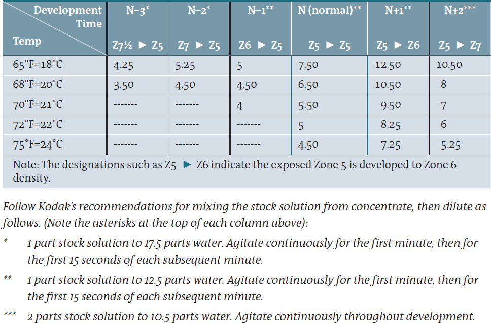
Diagram 9.6: Time/Temperature Chart for Developing Kodak Tri-X Film (ASA 320) with Kodak HC110 Developer in Tanks (for Tri-X film rated ASA 160)
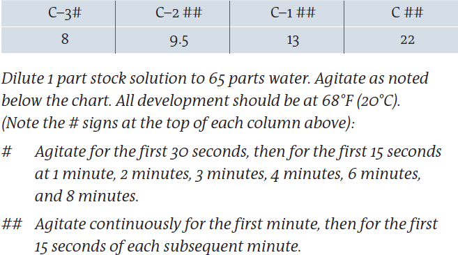
Diagram 9.7: Compensating Development of Kodak Tri-X Film with Kodak HC110 Developer
For a dramatic reduction in contrast, use the following:
Some Additional Comments on Diagrams 9.6 and 9.7
- In diagram 9.6, designations such as Z6
 Z5 indicate an exposed Zone 6 will be developed to Zone 5 density. “N” is normal development, in which each zone is developed to its exposed sensitization level.
 - “C” in diagram 9.7 is roughly equivalent to N–4 in the diagram 9.6 (if it existed!). Highlights are greatly reduced in contrast yet still maintain good separations. C–1, C–2, and C–3 produce still lower contrast.
- When using the compensating developer, give 2–3 stops extra exposure to the negative.
- Read the section under “Two-Solution Compensating Development for Negatives” later in this chapter for a significant improvement on this procedure.
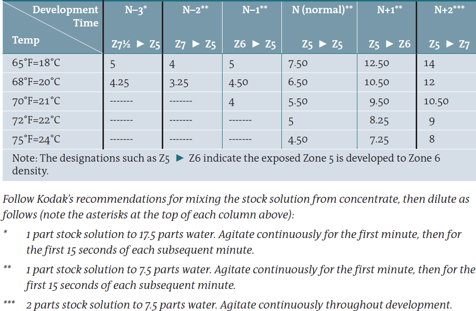
Diagram 9.8: Time/Temperature Chart for Developing Ilford HP5+ Film with Kodak HC110 Developer
(for HP5+film rated at ASA 300) Note: Times and dilutions are different from Tri-X.
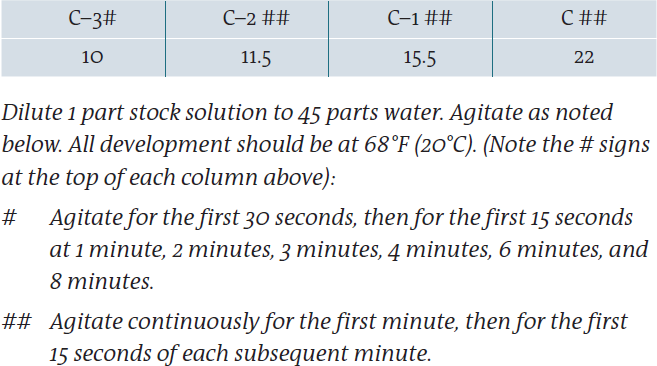
Diagram 9.9: Compensating Development of Ilford HP5+ Film with Kodak HC110 Developer
For a dramatic reduction in contrast, use the following Compensating Development:
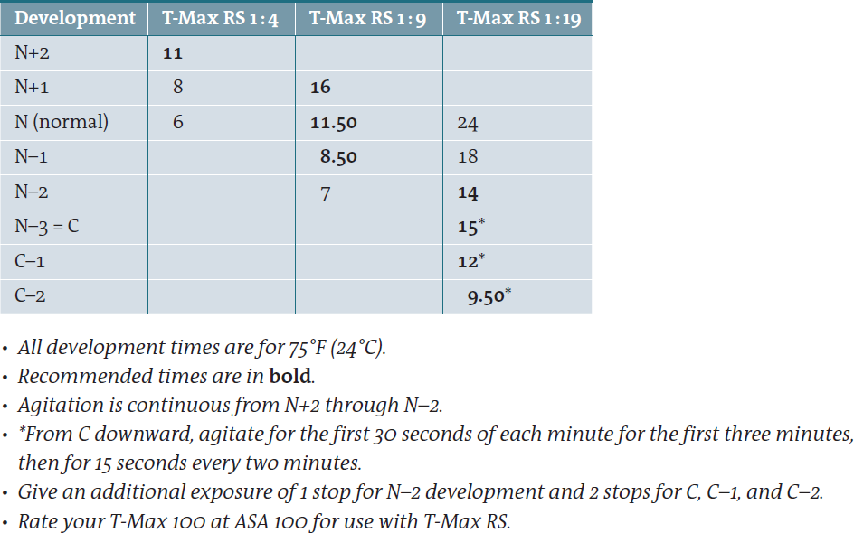
Diagram 9.10: Development of Kodak T-Max 100 Film in Kodak T-Max RS Developer
(for T-Max 100 film rated at ASA 100).
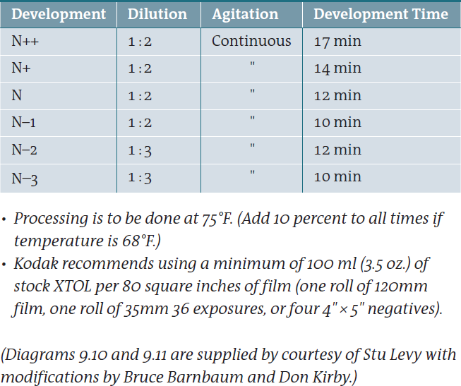
Diagram 9.11: Chart for Developing Kodak T-Max 100, Kodak T-Max 400, Ilford Delta 100, or Ilford Delta 400 Film with Kodak XTOL Developer
![]() A Note of Caution in Using a Compensating Developer
A Note of Caution in Using a Compensating Developer
Due to the extreme dilution of the working solution, there is very little active developer present. Therefore, develop only a few sheets, or a maximum of one roll, at a time. Otherwise the developer will be exhausted before full development is achieved. For roll film, it is wise to use a large tank (one containing several reels) with only one roll loaded onto a reel to assure a sufficient amount of developer in the tank.
When I use HC110 as a compensating developer in 90 ounces of working solution (which contains only 2 ounces of HC110 stock solution, or ½ ounce of the liquid concentrate), I limit development to four 4×5 sheets at a time. When using N–3, I limit myself to six 4×5 sheets at a time.
I strongly advise you to use the time/temperature charts only as a guide and starting point. Modify them as necessary for the best results. Even if you use the same negative/developer combination, a number of variables could make your results different from mine: the water in your area, your agitation procedure, your thermometer being a degree or two different, etc. As is so often the case, a little experimentation will give you optimum results.
If you use a different negative/developer combination, you’ll find that once you determine your normal development time, the percentage changes to N–, N– –, N+, and N++ are approximately the same as those on the charts—making them very useful as a starting point.
Explanation of Compensating Development
Diagrams 9.9 and 9.11 on the complete development charts for Tri-X and HP5+ list a development procedure for greatly reduced contrast via the use of extreme dilutions of HC110. Using this procedure, the dense portions of the negative are restrained significantly compared to the thinner portions. This procedure turns HC110 into a so-called “compensating developer” in the sense that it only partially develops the very dense highlights compared to the mid-tones and shadow areas—i.e., it “compensates” for their high sensitization level during exposure.
“C” development (C for “compensating”) is somewhat equivalent to N–3 of the adjacent diagram in the shadow areas, but the higher zones are reduced to lower densities than N–3 would yield. In effect, C is then equivalent to an N–3; but the unacceptably short development time necessary to produce N–3 would yield uneven results, so C proves to be a greatly improved alternative. Following the trend of the adjacent diagram, C–1, C–2, and C–3 produce progressively lower contrasts (see figure 9-1).
Compensating development depends primarily on the periods of non-agitation between the periods of agitation. Each time the negative is agitated, new developer is brought to all portions of it; but during the quiet periods, the developer exhausts itself on the dense areas because there is so little of it in the solution while more fully developing the thinner areas, hence the name “compensating.” The extra-dilute solution automatically prevents the densest portions from gaining excess density; it compensates for those areas potentially becoming too dense. Because this procedure depends on the quiet periods, it must be done by hand rather than by a mechanical, rotating drum with continuous agitation. But there is one minor drawback to this procedure: because the developer is so dilute, those areas that would normally be developed to Zone 1, or even Zone 2, may simply disappear. They have so little exposure that the dilute developer seems unable to bring them out in the developed negative. (The next section shows how to surmount this problem.) Even areas exposed as Zone 3 are somewhat anemic in the developed negative, but they are there, with discernible density. Beyond that, everything is OK. But this is a minor drawback to a procedure that yields huge benefits to control excessively high contrasts.
I learned about compensating development toward the end of 1979 and used it extensively starting with my discovery of the slit canyons of Arizona in January 1980 (figure 9-3). I then used it for my studies of the English cathedrals later that same year (figure 9-4). Thus, this purely technical procedure led to an astonishing artistic and expressive leap for me. This proved to me—and I hope will convince you—that the technical and the artistic aspects of photography cannot be separated. The two work in concert. The more you understand both aspects, the more your photography will improve. You cannot be a good photographer if you have great artistic instincts with little technical understanding, and you surely cannot be a good photographer with great technical prowess but little artistic imagination. You need both.

Figure 9-3: The Slit, Antelope Canyon
The negative received compensating development to retain as much detail as possible throughout the range—yet the brightness range of the scene still pushed the limits of the film. I allowed the darkest areas of the print to disappear in pure black, seeing their forms as so sensual that detail would have intruded. The scene was abstract; the image is meant to be abstract as well, with strong lines, forms, and contrasts.
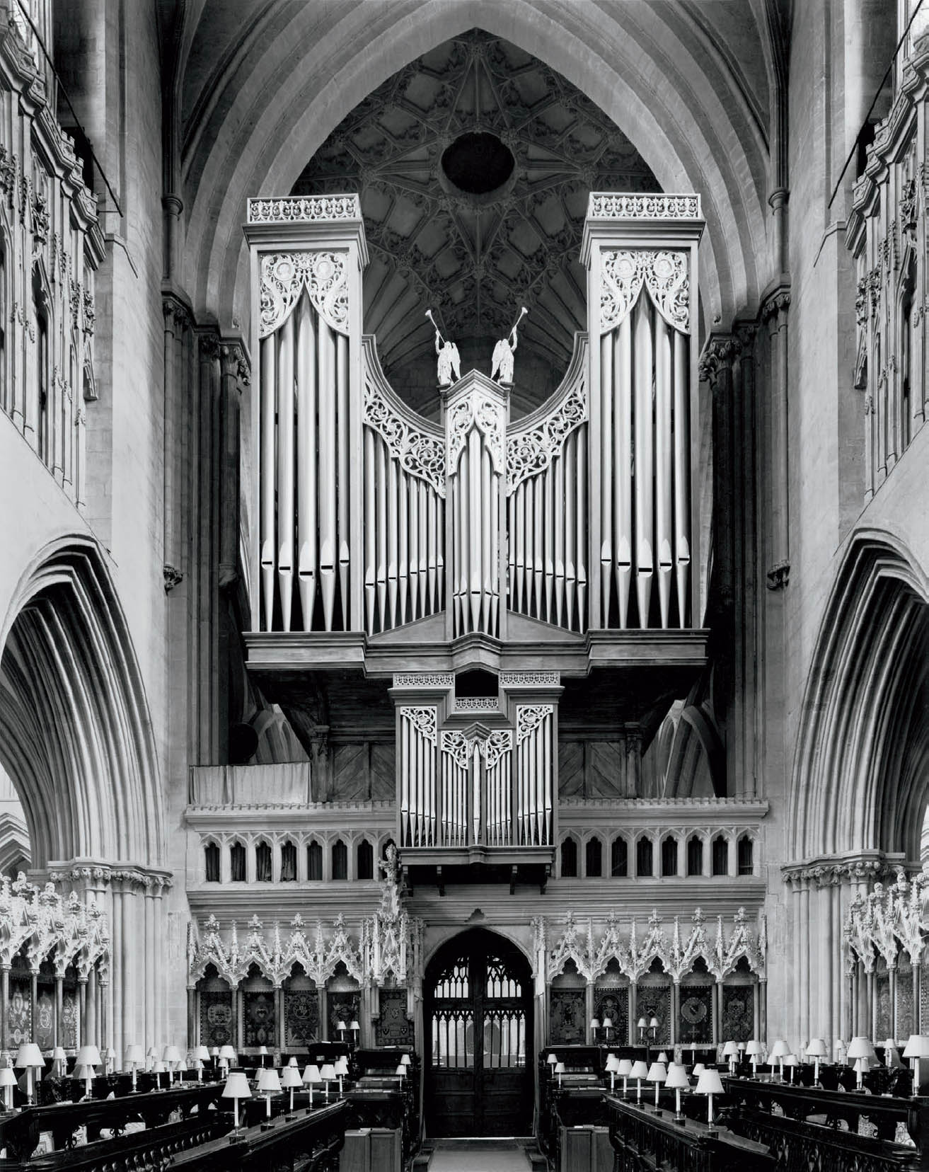
Figure 9-4: Choir and Organ, Wells Cathedral
Using precisely the same negative development procedure as in figure 9-3, the print has visible detail throughout; the viewer can see every bit of intricate detail that I saw while standing at the camera.
Two-Solution Compensating Development for Negatives
After using the compensating development procedure detailed above for nearly 17 years, I developed a superior method of dramatically lowering contrast in excessively high contrast situations or in prints where I want an extremely soft look, while retaining the lost lower values, and even enhancing all other values along the tonal scale. It involves the use of two solutions of HC110: first, a solution somewhat stronger than the normal dilution for Tri-X film in HC110 (1 part stock solution to 10 parts water); and second, a “compensating” solution (2 parts stock solution to 90 parts water).
I begin development in the first solution with constant agitation for the first 45 seconds; then I allow the negative to sit unagitated for the next 45 seconds. (Total development time at this point: 1 minute, 30 seconds.) This initial development in the stronger solution quickly develops Zone 1 and 2 close to their appropriate densities as seen in the bellows analogy. (See diagram 9.1 and imagine the look of the bellows at 1½–2 minutes development time.)
At this point, I transfer the negative to the compensating solution. I agitate for the first 30 seconds, primarily to dilute the amount of developer in direct contact with the emulsion (total development time at this point: 2 minutes). The negative sits unagitated for the next full minute. (Total development at this point: 3 minutes.) From this point, I revert to my usual procedure of 15 seconds agitation at the start of each minute followed by 45 seconds of non-agitation. At 10 minutes total development time (i.e., 10 minutes from the time the negative was first placed in the first developer), the negative is removed from the developer and placed into the stop bath, followed by the fixer.
Starting this procedure in the slightly stronger than normal development solution retains the lowest zones that would be lost with full compensating development, and tends to begin separating local contrasts in the mid and upper zones in a snappier manner. Then, before those upper zones attain too much density, the negative is placed into the extremely dilute compensating solution. This clamps a lid on the upper zones, preventing them from getting too dense but giving the mid and high densities wonderful local separations. All this results from the initial “kick” of the stronger first solution (figure 2-7 and figure 9-5).
Since devising this procedure in 1996, I have used it exclusively in place of the single solution developer. Whenever I’ve done direct comparisons, it yields better separations from the bottom to the top. Yet, I would have to admit that I do not know how I could have improved the final images I created in either the slit canyons or the English cathedrals had I employed this procedure with those negatives. But I do know that several images I have made since devising the two-solution procedure would have been impossible to print from a negative developed with the single solution. (And that may indicate that several attempted images I made prior to 1996 with the single solution that fell short may have made the grade if I had implemented the two-solution developer earlier, though I cannot imagine printing my slit canyon images any differently than I do with the older, single dilution methods. The two-solution process would give me more options in printing, but I would not put any of them into effect.)
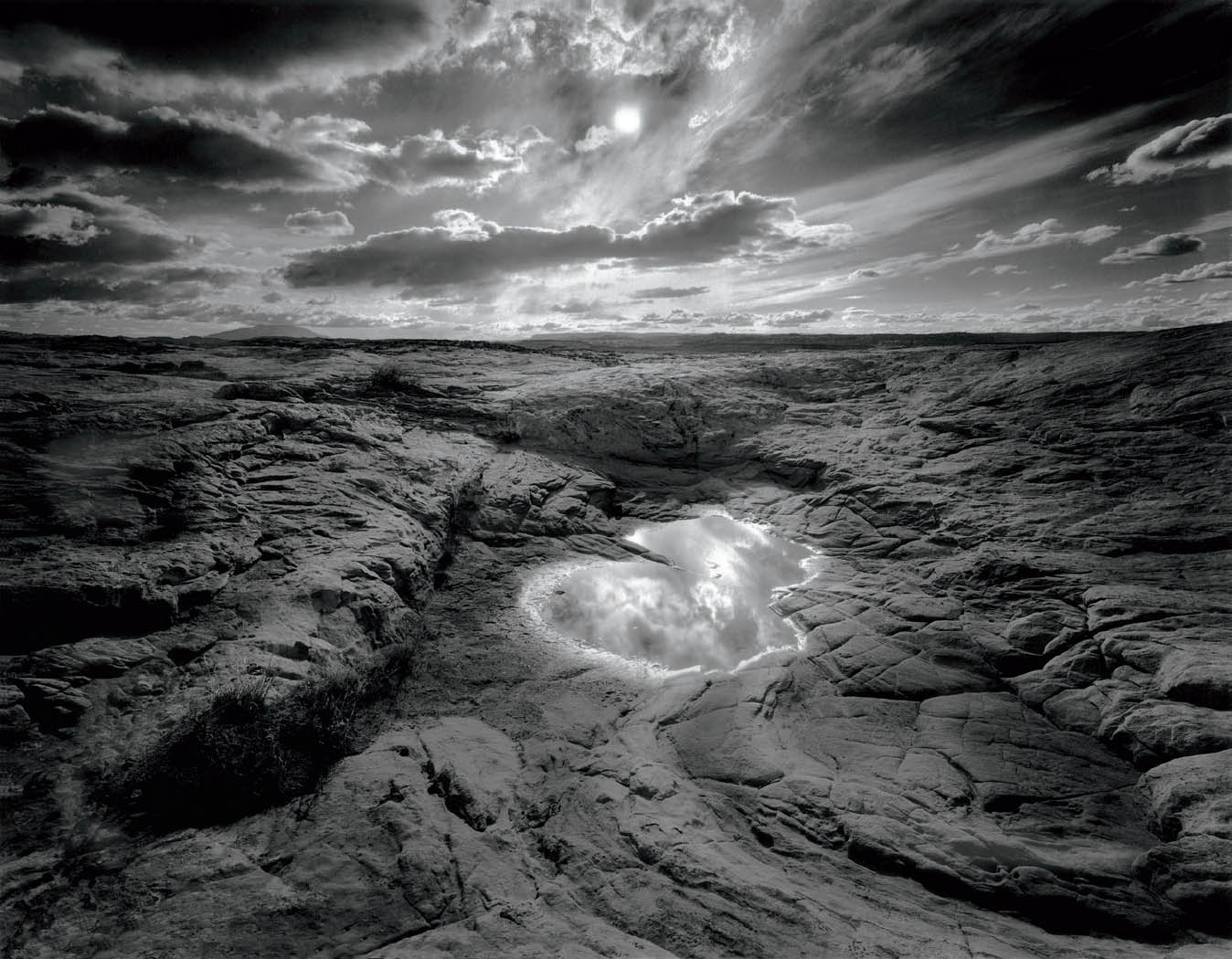
Figure 9-5: Slickrock and Reflecting Pool
Looking directly into the sun, I carefully placed the camera so that the clouds closest to the sun (but not the sun itself) were seen in the pool’s reflection. Contrast was excessive, from the sun and clouds to the sandstone in the foreground. When I came upon this scene in 1996, I had already evolved the two-solution compensating development, which gave me control of a greater contrast range than I could have retained with compensating development alone. This proves that every technical advance allows a further artistic advance.
To alter the final contrast level, I simply extend or reduce the development times in the first developer (agitation and non-agitation) by a few seconds in either direction. If I want more contrast, I add five seconds of agitation followed by five seconds of non-agitation; if I want lower contrast, I reduce both the agitation and non-agitation times by about five seconds. In either case, after removing the negative from the first solution, I agitate for about 30 seconds in the compensating solution to dilute the active solution in direct contact with the emulsion. This initiates the compensating effect that prevents excessive density in the upper zones. In all cases, I maintain the overall 10-minute development time for the two solutions. You can experiment with time variations to suit your needs. I now use this procedure in place of the pure compensating development procedure found in the Time/Temperature diagrams 9.6 through 9.9.
Development Procedures for Sheet Film and Roll Film
Both sheet film and roll film must be developed uniformly, from edge-to-edge, corner-to-corner. While you may be able to overcome inappropriate negative development (i.e., too dense or slightly too thin, too contrasty or not contrasty enough), it is virtually impossible to correct uneven negative development during printing. This section explains procedures that yield evenly developed negatives.
For sheet film development, we’ll look at these three common procedures:
- Hanger Development
- Tray Development
- Mechanical Drum Development
Hanger Development
In hanger development, the film is placed in metal holders, or hangers, which are immersed vertically into a large tank of developer. Agitation is accomplished by lifting the hangers completely out of the liquid, rotating them 90 degrees to the right, dropping them back into the tank, lifting and rotating them 90 degrees to the left, and repeating the procedure several times.
In practice, I lift the hangers up and lean them against the upper-right edge of the tank while rotating to the right, and against the upper left edge of the tank while rotating to the left. This action must be continuous, and neither too fast nor too slow, or unevenness could result. DO NOT STOP to allow the hangers to drain at the 90-degree rotation point. Instead, reverse the motion smoothly and swiftly, like a billiard ball hitting and ricocheting off the edge of a pool table. This will ensure even development.
My general procedure is to agitate continuously for the first minute, and then for each successive minute, agitate again for the first 15 seconds with the remaining 45 seconds of each minute devoid of agitation. Only with the N+2, C–3, and two-solution compensating procedures does this vary. Agitation is continuous for development of T-Max 100 developed in Kodak D-76, T-Max RS, or XTOL.
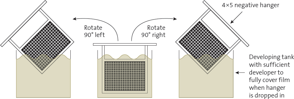
Diagram 9.12: Agitation Procedure for Sheet Film Development in Hangers
After dropping the hangers into the tank and banging them down several times to dislodge any air bubbles on the negatives, agitate by raising the hangers first against the left edge of the tank and rotating 90 degrees to the left, then dropping them back into the tank. Then raise them against the right wall of the tank, rotate 90 degrees to the right, and drop them back into the tank. Repeat the procedure for all agitation. Do not hesitate at the 90-degree position, but immediately return the hangers to the tank.
Tray Development
Tray development is theoretically simpler but often much more difficult to master without damaging the film during development. The procedure is to slide the film into a tray of developer one sheet at a time, stacking one sheet on top of another. Agitate by pulling out the bottom sheet and laying it on top of the stack, making sure the top sheet is then fully submerged. Repeat this simple procedure continuously.
This procedure must start with a pre-soak of the negatives, or they will stick to one another like glue. To begin, submerge the first negative in plain water for several seconds, then submerge the second for several seconds together with the first, then add the third, and so on. After all of the negatives have been submerged, run through the stack several times before transferring them to the developer. This will ensure that all of the negatives will separate from one another and that development will begin smoothly.
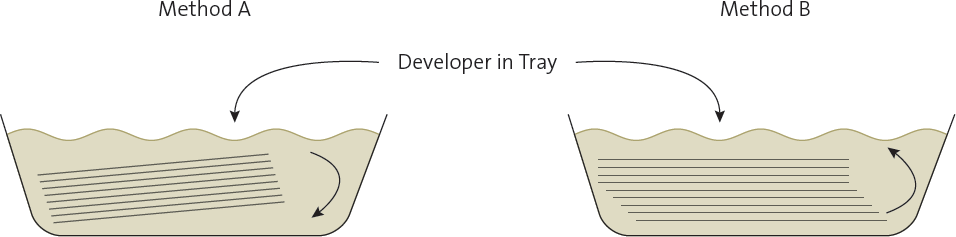
Diagram 9.13: Agitation Procedure for Sheet Film Development in Trays
There are two methods of tray development. Method A shows that by cradling the entire stack of negatives at a slight angle with one hand, the top sheet can be removed and slid under the bottom sheet of the stack. Continue the procedure without pause for the entire duration of development. Method B shows agitation by pulling the bottom sheet from the stack and placing it on top. This procedure also requires a constant shuffling motion from bottom to top from the start of development until development is complete. With practice, Method A may prove less subject to scratching.
For those who have mastered this procedure, 15 to 20 negatives can be developed at a time. The pitfall is that it is very easy to scratch negatives against a sharp corner of the one above or below during agitation. Experience will overcome this initial problem.
Because agitation in trays is continuous, while in tanks it is periodic, the characteristics of the developed negative are different. In the tank, 45 seconds of unagitated “hang time” per minute slows development, so for equal development times the hanger-developed negative is less dense and contrasty than the tray-developed negative. Of course, if many negatives are developed simultaneously in trays, there is a long period of non-agitation for each negative as it slowly moves from the top of the stack to the bottom (before it is again agitated by being pulled out and placed on top). This lengthy period of non-agitation makes tray development closer to hanger development.
In the compensating procedure, periods of non-agitation are essential to create the compensating effect. During the “hang-time,” the dilute developer in contact with the heavily sensitized portions of the negative is quickly exhausted; further development ceases until the next agitation brings new developer in contact with those areas. During that same hang-time, however, the thin portions of the negative cannot exhaust the developer as quickly, and they are more fully developed. This means that if you use tray development, the compensating effect is lost unless you allow periods of non-agitation.
Mechanical Drum Development
Mechanical developing procedures, such as automatic periodic agitation in nitrogen burst tanks or continuously rotating drums such as Jobo, are perfectly fine negative development methods. If you use such methods, be sure the development is even throughout the negative. Also be aware that continuous agitation in a mechanical processor precludes the possibility of compensating development, since non-agitation periods are mandatory for the compensating process to be effective. Use a drum processor for negative development in the normal ranges, but switch to hand development and periodic agitation to achieve the compensating effect.
Development of roll film on spiral reels should be done only in an invertible tank, not in tanks requiring agitation by spinning the reels. The only agitation that I have found to yield uniform development is a wide, upward sweep to the inverted position, and then a return sweep—like an inverted pendulum with your elbow as the fulcrum—and, perhaps, a 90-degree turn along the way (the 90-degree turn is not necessary with each inversion; I do it periodically). Spinning the tank should never be done because it creates additional agitation and density along the reels, which translates to light streaks along the edges of the print. If your prints lighten noticeably along the edges, it’s a good bet that spinning the tank is to blame.
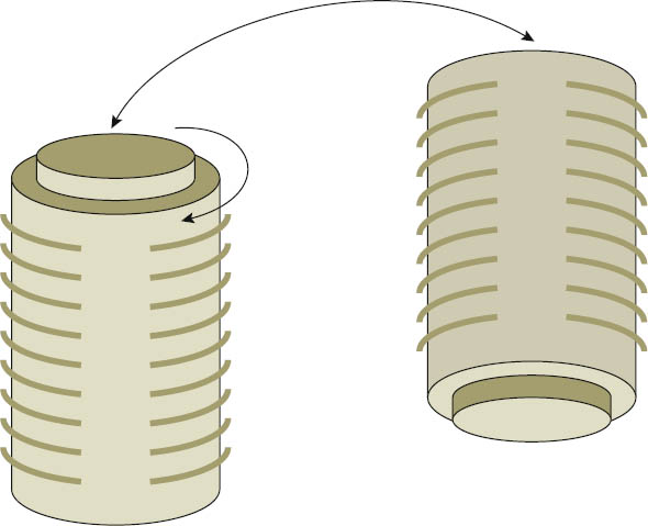
Diagram 9.14: Agitation Procedure for Roll Film Development in Invertible Tanks
Agitate by inverting tank fully and spinning it 90 degrees when bringing it back to upright position.
One common mistake in developing roll film is to load the reels first, place them in the tank, then pour in the developer through the small hole at the top. This is the worst way to start development! The reason is that some portions of the negative will be in contact with developer for 20–25 seconds before other portions are finally submerged, and uneven development is virtually assured. A better procedure is to remove the reels first and fill the tank with developer, and then load the film on the reels. (Of course, it helps greatly to load the reels in total darkness.) Then drop the reels into the tank, clamp on the lid, and begin agitation. Once the lid is clamped on, you can turn on the lights during the development time. Toward the end of the development time, turn off the lights, remove the lid completely, dump the developer quickly, and pour in stop bath from a nearby flask, premixed with the proper amount of liquid. Once development is stopped, you can pour out the stop bath and pour in the fixer in a leisurely fashion.
Completing Development with a Stop Bath and Fixer
For both roll and sheet film, place the negative in a stop bath for several seconds of continuous agitation to quickly stop development. Then fix it for the recommended time in the fixer. With most standard fixers (I use Kodak standard fix with hardener), 10 to 15 minutes is sufficient; excessive fixing may bleach the negative slightly. After you immerse the negatives in the fix and agitate them for two minutes or more, you can turn on the lights for inspection. A subsequent wash of 10 to 15 minutes—or five complete changes of water—makes the negative archivally permanent.
Developing negatives is not my favorite pastime, but proper development is the only way to continue the process started when you exposed the negative. There can be no substitute for a well-conceived, well-composed, well-exposed, and well-developed negative. If any of the four is given short shrift, there will be a distinct loss of quality in the final, all-important step: the well-printed photograph.
Appendix 1 contains tests for film ASA and contrast levels of your developed negative. It shows a method for determining normal contrast development for your film/developer combination, as well as other excellent tests for materials and equipment.
The Zone System and Roll Film
How can you use the zone system and contrast control procedures with roll film? To be sure, they don’t work quite as well as with sheet film. All negatives on a roll are developed the same way, whereas each negative on sheet film can be developed exactly as desired.
However, several options are available for roll film. First, you can use more than one film back or camera body, designating each back or body for a different contrast development level. By employing a sufficient number of backs, any desired development can be produced and nothing is lost. Most likely you would use only two or three backs and make small compromises. With three backs, you could use one for contrast expansion, one for normal or slightly reduced contrast, and one for compensating reduction. With two backs, you could use one for normal or reduced contrast and another for increased contrast. However many film backs you have, expose each photograph on the roll that most closely fits your needs.
![]() Choose any great photographer—let’s say Ansel Adams, for he was great and his work is so well known—and ask yourself how many truly great photographs he produced in his lifetime (50+ years of photography). 50? 100? 200? Maybe more. But that is about four per year at best!
Choose any great photographer—let’s say Ansel Adams, for he was great and his work is so well known—and ask yourself how many truly great photographs he produced in his lifetime (50+ years of photography). 50? 100? 200? Maybe more. But that is about four per year at best!
If additional backs are either too expensive or unavailable for your camera, another approach may be possible. If you can unwind the film from your camera prior to complete exposure of the roll (a procedure that is possible with most 35mm cameras, but impossible with 120mm film), then carry several rolls with you at all times, each marked for different development. Whenever you encounter a scene that requires different development from the roll currently in the camera, unwind the one inside and label the frame it is on, then wind in the appropriate roll just beyond the frame last exposed (to avoid a double exposure) and shoot. If the next scene requires the previous roll again, unwind the current roll, mark the frame number on the roll or cassette, and wind in the roll you need just beyond its last exposed frame. This may be time-consuming and inconvenient, but it allows for proper development for each photograph.
However, my best suggestion involves another approach that shocks most people when they first hear it, but it really works! Whenever you expose a frame that is truly exciting to you—one that you feel will be a superb photograph—unwind the roll immediately and develop the entire roll for that particular exposure! You may want to make several variations of the exposure first. You may try different camera positions, filters, lenses, aperture and shutter speed combinations, etc., but then remove the roll! That may be a very surprising suggestion, but what do you lose? Film is the least expensive part of photography, so why compromise on a potentially great shot? I have seen people leave a roll of 20 exposures in the camera for months because the last two frames are not yet exposed. That makes no sense. Keeping film in the camera after a great exposure just to finish out the roll is equally absurd.
A second consideration may be even more important in support of this radical suggestion. Choose any great photographer—let’s say Ansel Adams, for he was great and his work is so well known—and ask yourself how many truly great photographs he produced in his lifetime (50+ years of photography). 50? 100? 200? Maybe more. But that is about four per year at best! Now, with that in mind, how many truly great photographs do you think you actually have on that one roll? When you stop to think of it, you don’t lose anything by trying this suggestion.
The only other alternative is to get the best “average exposure” on every frame and develop normally, hoping that high- or low-contrast papers will provide enough leeway to yield a good print. (This is a poor alternative to the previous suggestion.) This is the usual approach, and while it renders contrast control useless for the negative, it does show that use of the zone system for determining the initial exposure is still very important.
Once you know the zone system, you will have no need to bracket your exposures. Bracketing is nothing more than a fudge factor for those who are unsure of what they’re doing. Let me hedge on this by saying that periodically—and only on rare occasions—you may want to make more than one exposure and development because the lighting is unusual, weird, or perhaps very “different.” Doing several exposures along with different developments makes sense in strange situations. You can learn from them while making at least one usable negative along the way. Except in such rare cases, a complete understanding of both the zone system and your film’s characteristics should put you right on target without the need for extra exposures and time-consuming developments.
I strongly recommend that you avoid bracketing because it promotes sloppy field techniques. I’m not against making a second exposure of a negative that may be extraordinary just as a back-up in case the first is damaged, but the backup negative should be the same good exposure as the first one.
Negative Materials and Developers
The commonly used panchromatic materials (i.e., Kodak Tri-X, Ilford FP-4+, HP-5+, Fuji Neopan Acros 100, and comparable films by other manufacturers) are generally developed by a selected few developers (i.e., Kodak HC110 or D-76, Edwal FG-7, Rodinal, Ilford ID-11, etc.). Kodak T-Max films or Ilford Delta films (both using T-grain technology) can be developed with Kodak T-Max or XTOL developers. Other developers may be employed for special purposes. The question often arises as to which combinations of negative materials and developers give the “best” results. There are differences, of course, and some of the combinations are better for certain purposes than others—but which?
If sharpness or smooth grain is a prime consideration, then it’s best to recognize that the slower speed films have finer grain and generally better sharpness than faster films. But how do the various developers affect your images? My experience indicates that the film itself, along with the length of development (but not the developer per se), determines the final outcome to the greatest extent. In other words, if one of the films mentioned above were developed by each of the developers listed, it would be difficult to show that grain or sharpness varied significantly as long as the development times were approximately equal. Excessive development increases grain noticeably.
There are people who claim that certain combinations are clearly superior to others, but even after inspecting the evidence carefully, I remain unimpressed. The differences range from extremely subtle to nonexistent and are of marginal importance. Furthermore, a very fine grain film may have finer grain than a coarser grained film no matter what developer is used to process either one.
There are other, more important, considerations regarding film/developer combinations. First, which combination yields the greatest detail in both highlights and shadows? Some film/developer combinations show great separation of shadow tonalities but little separation in highlights. Other combinations show good highlight separation but little shadow separation. I haven’t tried all of the combinations (after all, I’m a photographer, not a lab technician), nor have I tried all of the films or developers separately. Generally, I shoot 4×5 sheet film and occasionally 2¼ × 1⅝. Long ago I settled on Tri-X film for my sheet film and Ilford Pan F, FP4+, and HP5+ for roll film (for increased, normal, and decreased contrast respectively). The results have been excellent, with each of the films yielding smooth tonalities and fine grain. I use HC110 as my prime developer because I find that it produces good highlight and shadow separation. I develop the T-Max 100 in T-Max RS or XTOL.
Whatever you choose as your film/developer combination should be based on your goals as a photographer. If highspeed film is necessary for your photography, avoid testing low ASA/DIN films. If fine grain is critical to your imagery, stay away from high-speed films; they are noticeably grainier. A little testing will show you which film/developer combination yields the best highlight and shadow details for your purposes.
Testing is a means to an end, and the “end” is the best possible photographs you can make. Don’t waste your time testing and retesting, refining and further refining your test results. There is a difference between photographers and sensitometrists. If you are a photographer, start making real exposures for expressive photographs after some initial testing. Any modifications of your test results can be made during the “real” shooting.
Another consideration is contrast control. Which combinations allow the greatest flexibility for expansion or contraction of contrast? In general, most of Kodak’s standard or T-grain films are quite good in contrast flexibility, though Plus-X film lacks expansion capability to such an appalling extent that I avoid it completely. More development fogs Plus-X overall, increasing density greatly without increasing contrast appreciably. All Ilford films seem to have wonderful contrast control characteristics, and their gradations of tonality are beautifully smooth—better, in fact, than the equivalent Kodak films. But Ilford HP5+ becomes excessively grainy with increased development, though it is quite smooth and fine-grained with reduced development.
Be aware of a strange quirk in Kodak’s marketing: it produces two distinctly different films named Tri-X. A quick clue to the fact that the films are different is that sheet film Tri-X is rated at ASA 320, whereas roll film Tri-X is rated at ASA 400 (and the roll film Tri-X Pan Professional is rated at ASA 320). Why Kodak gives these different films identical names is strange indeed.
Concerning developers, each one has its proponents, but I find some of the arguments arcane and immaterial. Whether one developer produces a finer edge demarcation when measured on an optical bench is immaterial because we all look at photographs with our eyes, not with a microscopic caliper! Of material importance is the separation of tonalities in highlights, midtones, and shadows, the effect of the developer on film speed, its characteristics in contrast expansion and contraction, and its ease of use.
For example, I have found that using Kodak HC110 to develop either HP5+ or Tri-X, according to the time/temperature charts, separates tones quite nicely throughout the entire spectrum. It produces noticeable grain during expanded development (particularly with HP5+) but extremely fine-grained negatives with the compensating procedure. It’s easy to use because it’s a liquid concentrate, which can be quickly diluted. It also lasts a long time in the bottle without noticeable deterioration, even as it turns dark brown (but there is a limit). It suits my purposes well. I feel that these are the important considerations, and I recommend that you judge your choice primarily on the same considerations.
Testing and experimentation will uncover combinations that are best for you. My choice may or may not be your choice. The important thing is that you are satisfied with your own combinations. Your goals are surely different from mine, and your final combinations may be different to enable you to best achieve your goals. I stated my film and developer combinations as examples, not as recommendations, as I have done with other examples throughout this book. Please accept them as such.
In addition to the commonly used negative materials and developers discussed above, there is an abundance of materials for specialized purposes. Orthochromatic film is sensitive to a narrow segment of the visible spectrum (the blue wavelengths) and can be used to great advantage. Blue objects, such as the sky, are rendered very light, while red objects are very dark. The uncommon tonal renditions created by this film can be very intriguing.
Infrared film can yield truly bizarre images, and with care and subtlety on the photographer’s part they can go beyond the superficial realm of stark, almost shocking impact to become quite creative and insightful. As with so many other tools, most people use this film sporadically for special effects and immediate impact rather than delving into its expressive possibilities. If you are interested in these or other specialized films, I suggest you work with them over long periods of time, as if you were nurturing plants in your garden. Cultivate them and gradually get to know them, and what they can do for you.
Not only are there specialized films, but also specialized developers for them. They can be used with panchromatic, orthochromatic, or infrared films, yielding some very exciting and unusual results. This is purely in the realm of creative experimentation, and you will have to discover the possibilities yourself. I suggest obtaining data books and brochures from Kodak, Ilford, and the other manufacturers to get basic information before charging ahead blindly. Such books will offer information concerning the characteristics of the various materials and give you a starting point for your experiments. The rest is up to you!
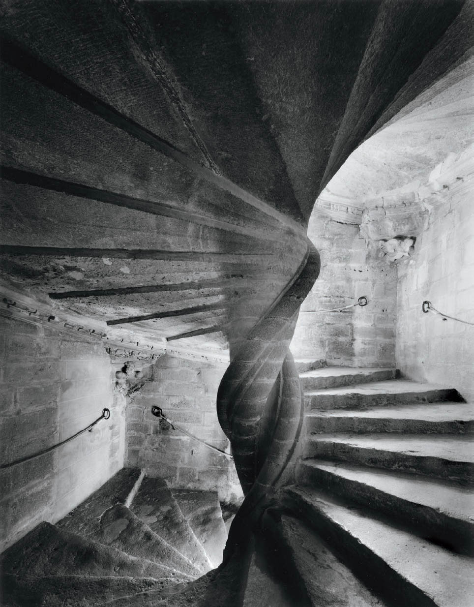
Figure 9-6: Eclairé
The four story spiral stairway at Chateau Lourmarin, in Provence, France, is a true work of art in masonry, much like an Escher drawing, looking almost the same upside-down. Its contrast is excessive, with window light at various levels providing the only illumination. I used my widest angle lens to adequately encompass and convey its magnificence, and a two-solution compensating development for the exposed negative.