
Solutions in this chapter:
Creating a Tape Writer
Can a MINDSTORMS robot be made to draw or write? Sure. Believe it or not, that’s not even a very difficult thing to implement. In the following pages, we will show you two projects, the first mainly meant for drawing and the second for writing. Both of them require some additional parts, but both have wide margins for modifications and allow for less demanding variants.
Many of you may already know that Logo is a programming language specifically targeted to education. Born in the late 1960s at the Massachusetts Institute of Technology (MIT), Logo is derived from Lisp (with far fewer parentheses!) and features interactivity, modularity, and extensibility. More than a programming language, Logo is a learning tool which has gone through a number of changes and improvements over the years.
The most known characteristic creation of Logo is the Turtle, a symbolic turtle that moves across the computer screen according to the instructions it receives. With simple instructions such as forward 10, the turtle moves straight 10 units, and with right 90 it turns clockwise 90 degrees. The statements penup and pendown specify whether the turtle leaves a track behind it, thus producing drawings, or rather just moving to a different location. Obviously, the language includes many other commands, but these are enough to understand the principles of the Turtle graphics that made Logo so famous.
What many people don’t know is that in its first version, the Logo program controlled a small robot that actually drew lines on the floor. In subsequent releases, the turtle became just a virtual animal on the screen. Our interest here, however, is in replicating the first robotic version.
Note
Dr. Seymour Papert was one of the early promoters of Logo, and he designed the original Turtle. Under his guidance, the Epistemology and Learning Group at MIT devised the first programmable brick, whose concepts led to the development of the LEGO MINDSTORMS line.
The idea is quite simple: Build a small robotic platform that’s able to go forward and backward, turn in place, and lower and raise a pen. Despite this apparent simplicity, if you want aturtle that works as expected, the task has many stringent requirements that must be adhered to. For instance:
The robot must go absolutely straight.
The pen must be exactly in the pivoting point of the robot, because it must stay in the same place on the floor while the robot turns (otherwise, it would trace a curve).
You need a tracking system to measure both traveled distances and angles.
If you remember the driving architectures described in Chapter 9, you already know the solution to the first point: Use a dual differential drive. The simple differential drive is suitable for this project only if you apply an active control to the wheels to be sure they travel exactly the same distance, whereas the synchro drive would work as well but at the price of greater complexity and a not so evident change in orientation during action. Another advantage of the dual differential drive is that it requires a single encoder to comply with point 3: When the robot goes straight it measures the covered distance, and when turning it measures the angle.
Okay, so we have requirements 1 and 3 covered, but there’s still the matter of the pen being the center of rotation, which is at the midpoint of the imaginary line that connects the wheels. Conceptually, it sounds easy, but you have to build your robot with this point in mind.
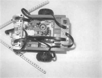
The original turtle—a differential drive—featured a transparent plastic dome to cover the gears. We provided our turtle with a triangular shape (see Figure 18.1), because we wanted to mimic the screen turtle of some widespread Logo systems. Anyway, those V-shaped beams are definitely not necessary and you can shape your own turtle according to your wishes.
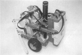
Our differential drive does not use a caster wheel, because they tend to affect the direction of the robot slightly when resuming straight motion after a turn. With casters, the straight lines would have a short wiggly segment, so we preferred to use a simple tile as the third supporting point. To keep the friction on the floor to a minimum, we placed the NXT suspended behind the drive wheels, like a sort of counterweight, bringing the COG of the robot very close to the drive axles, and thus, most of the weight upon the drive wheels.
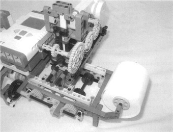
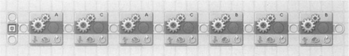
Let’s start exploring the dual differential drive chassis that drives the robot (see Figure 18.2). The gearing is more compact than those shown in Chapter 9, but it works exactly the same way: One motor makes the differential gears and the wheels rotate in sync (motor C), and the other rotates them in the opposite direction (motor B in this case). The dark gray 16t gear right in the middle of the photo is an idler gear which connects the other two 16t gears; its center hole is not cross-shaped and thus it doesn’t couple with the long joined axle that crosses the base of the robot.
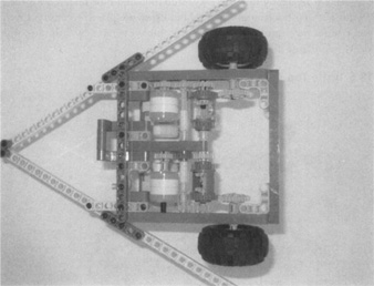
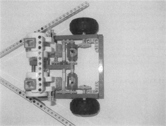
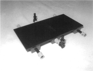
Looking at the bottom, you can see the front skid roller (see Figure 18.3). Figure 18.4 shows a side view of the turtle pen mechanism.
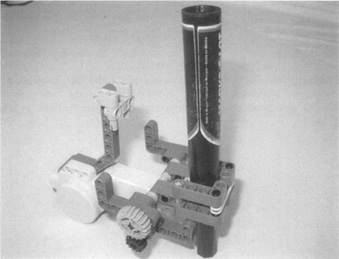
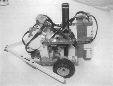
The pen is a non-LEGO part, a common marker with its body wrapped in adhesive tape so as to make it fit tightly into the 2x2 stud’s squared hole reserved for the purpose. It stays there with nothing but friction. Two rubber bands are placed to ensure this friction.
The pen control mechanism is a swinging assembly operated by a third motor (in this case, motor A) (see Figure 18.5).
Now the turtle is ready. Place a large piece of paper on the floor, uncap the pen, and adjust its height so that it touches the paper gently when it is in the down position (see Figure 18.6). We strongly discourage you from writing directly on the floor. We’re sure somebody won’t like it!
The first task in programming the Turtle is to create the primitives that control the basic actions. Let’s start with the easiest ones: the commands to move the marker up and down. A short degree rotation to the marker motor (motor A) does the trick—nothing more is required. In this case, it is easiest to set the marker down position on the ground and use the view rotation function on motor A to see the number of degrees necessary to move the marker adequately above ground. For this design, 75 degrees did the trick.
The forward and back commands, meanwhile, are not very difficult to implement, but require that you dig into the physical properties of your robot. You must discover what distance it covers for any increment of the motor rotation. Programming the distance you want the robot to travel affects the size of the image you are intending to create. If you have a desired size object—for example, a square with 30cm sides—you can calculate the amount of motor rotation required for the turtle to create this length. All you need to know is the wheel circumference (in this case, 17 cm to 17.5 cm) and the gear ratio from the motor wheel (in this case, a 12- to 24-tooth ratio [1:2]). If you have a fabric measuring tape or other flexible measuring tape, it is easy to measure the wheel circumference. If you do not have this type of measuring tape you can just as easily measure the distance you want by rolling the wheel on a ruler one rotation. For the wheels used in this design, the wheel circumference varied from 17 cm to 17.5 cm, compressed or uncompressed. Because these wheels were designed with a large amount of built-in shock absorption, they will vary in diameter with the amount of weight placed on them.
To get our turtle to travel exactly 30 cm, for example, all we have to do is multiply the gear ratio by the ratio of the distance we want the turtle to travel, and divide by the wheel circumference. This is displayed in the following equation:
For our purposes:
You should use this rotation for the forward drive motor; in this case, motor C (see Figure 18.7).
This is the theory. The actual robot will probably require some in-the-field tuning, because the distance covered by the wheels is affected by other factors: The weight compresses the tires and reduces their diameter. There might be some slippage too. We suggest you proceed by experimentation, making your turtle draw a line, measuring it, and then correcting the factor until you’re happy with the result. All this process is meaningful only if you care about having your turtle use units that correspond to some common length unit. If you don’t care, simply program the robot to go forward two or three rotations, for example.
Now the last part: the turning primitives right and left. If you remember from before, you find that the change in orientation □OR (in radians) depends on the distance covered by the wheels (TR - TL) and the distance between the wheels (B). When the dual differential drive turns in place, both wheels travel the same distance (T) in opposite directions, so we can express the equation in simplified terms (see Figure 18.8):
□OR = 2 xT / B

Actually, you know the □OR you want to get; it corresponds to the desired turning angle of the turtle, and it’s the input to your subroutine. What you’re looking for is the Count of the rotation sensor that produces that □OR. The first step is to obtain T from the previous equation:
For our robot to make a star, we need the robot to make a very sharp turn. The angles of the points of a star are 36 degrees. For our robot to make this point, it has to turn 180 -36 degrees, or 144 degrees. To make any turn we need to consider the outer turn angle for the robot. This may seem a little confusing at first, but if you stop to think about the way the robot travels, it makes sense.
Now that we know our robot should turn 144 degrees to make a star, we need to figure out how to program it to do so. The following equation will explain this process:
For our purposes:
You should use this rotation for the turning drive motor; in this case, motor B (see Figure 18.9).
The power level is reduced to allow the robot to make more accurate angles. You may need to adjust this more depending on the friction of the surface on which you are writing.
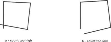
As for the forward motion control, this one will need some adjustment too. Your turtle is not likely to draw proper angles on the first try. We suggest you make it draw a simple polygon, such as a square or an equilateral triangle, and check that it closes the path properly. For example, the sequence of four forward 1 rotation right 518 degrees should draw a square; if the last segment intersects the first one but not at its starting point, the count is too high, and you have to increase the rotation (e.g., 520 degrees instead of 518 degrees) and vice versa: If the square doesn’t close at all, you should decrease the rotation (see Figure 18.10).
Instead of working on the software, you can often change the geometry of the robot. Altering the distance between the wheels by moving them in or out along the axles is a very effective way to tune the robot. Make small adjustments until your square comes out perfect.
Once you have the correct rotation, it is easy to program the turtle to make a figure with a count loop. Figures 18.11-18.14 show an example program for creating the star.
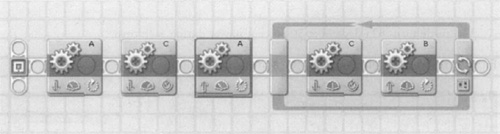
The marker is lifted and then the turtle travels to a specific location. Then the pen is placed down on the surface and the turtle enters a five-count loop that creates a star.
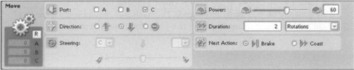
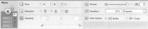
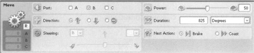
In the star, the turtle moves forward two rotations at 60 percent power before each turn.
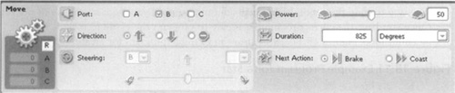
The turtle turns 825 degrees at 50 percent power during each turn.
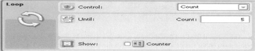
The turtle executes a total of five counts, creating the five lines of the star.
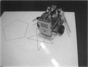
Work patiently on your turtle and its code. The result will astound you!Figure 18.15 shows our turtle drawing an almost perfect five-pointed star and a pentagon.
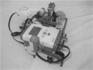
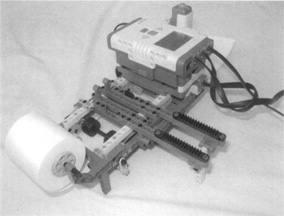
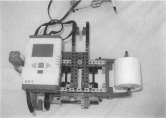
The second project in this chapter uses an approach somewhat opposite to that of the Logo Turtle: Here it’s the paper that moves, while the robot stays still. The principle is similar to the one used in ink-jet printers: A mechanism feeds the paper under a writing head, which by itself moves perpendicularly to the direction in which the sheet advances. From what you learned in the previous chapters, you can tell that such a system has two degrees of freedom (DOF), controlled respectively by a paper-feeding motor and the writing head motor (actually, our robot implements a third DOF, needed to move the pen up or down over the paper). This Tape Writer is also a Cartesian system, because the movements of the mechanisms are linear and perpendicular to one another.
This robot requires some extra parts: gear racks, beams, and a large tile; however, if you don’t have the needed parts, there are many things you can do to downsize the project to keep within your inventory (we’ll describe some of them).
What we have in mind is a robot that writes on one of those common paper tapes made for printing calculators or cash registers. One motor moves the paper strip forward and backward, and a second moves the pen in a perpendicular (side-to-side) direction. The third motor controls the up/down pen movements.
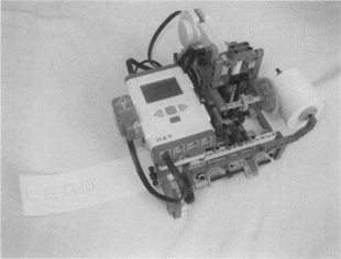
Starting from the end, here’s our finished robot that writes the word LEGO(see Figure 18.16).
Analyzing the Tape Writer in detail, you can see that it’s made of a body and three subsystems, all of them with one degree of freedom:
The body provides the main structures and hosts the paper transport system.
There’s a movable carriage over the body, which transports the pen in a direction perpendicular to the tape.
Over the carriage, the pen assembly moves up and down.
At the bottom of the body, there’s the writing surface, a smooth surface that presses the paper against the wheels.
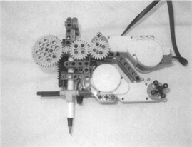
Looking inside the main body, you catch a glimpse of the transport wheels and the pen assembly (see Figure 18.17).
The wheels are operated by a motor through a 16t gear, a 36t gear, and two connected 12t and 24t gears (see Figure 18.18). This latter geartrain is necessary to keep the two groups of dragging wheels turning in the same direction. You need the paper to go back to shape some letters, and this is why there are wheels both before and after the pen.
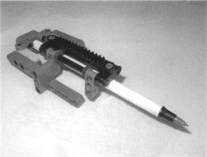
Removing the pen carriage, you see the wheels and the paper tape down below (see Figure 18.19). The carriage is translated using a rack and pinion assembly, powered by a second motor on the body.
A second rack and pinion system, operated by the third motor, controls the vertical movement of the pen (see Figure 18.20). Figure 18.21 shows a close-up image of the pen.
The writing pad is one large 8 x 16 stud tile piece (see Figure 18.22). If you do not have this piece you could use a bunch of little tiles covering a plate as the writing pad. The irregular surface covered with studs wouldn’t work. In case you don’t have tiles, or you do not have enough of them, cover the plates with a smooth, thin support, such as a glossy cardboard, an aluminum or plastic sheet, or anything else similar that comes to mind. You can also build a top out of standard LEGO bricks laid on their side, which should provide an even more regular surface than tiles.
The writing surface is an independent part linked to the main body through short rubber bands (see Figure 18.23). Those bands pull the surface up against the pen and against the wheels of the feeding mechanism.
Programming the writer may seem difficult, but it is much easier to divide the program into My Blocks for each letter and then bring them together in one large program. Our robot uses a loop program to write the word LEGO and a touch sensor to order more copies. Figure 18.24 displays this program.
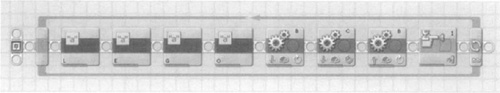
As you can see, the My Blocks are labeled with the letter they write in the program. The program writes the four letters and then lifts the pen up, advances the paper roll so that you can view the words, lowers the pen to the original starting position, and then waits for the touch sensor to order another copy. The My Blocks can be small or large programs depending on the complexity of the letter. For example, the program for the letter “L” is a very short program displayed in Figure 18.25. However, the program for the letter “E” requires much more movement.
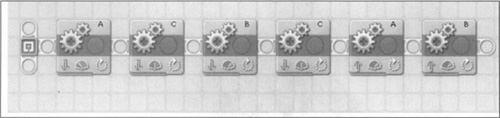
In this program, the A motor controls the vertical movement of the letters, the C motor controls the horizontal movement of the letters, and the B motor lifts the pen up and down. To draw the letter “L” the A motor moves down the entire length of the vertical movement from top to bottom. For this design, that is 130 degrees of motor rotation. The power level is set to 35 percent to give a crisper line. The pen then feeds the paper running C motor 300 degrees at 50 percent power level. You can adjust this value depending on the size font you desire. Then the pen is moved up to the starting height and over a spacing of 200 degrees, and is placed down, ready to write the next letter. You can change this spacing depending on how much space you want between the letter characters. Figure 18.26 shows the program for writing the letter “O.”
Once you create a My Block for any letter you want, you should save them so that you can recall that letter later. Who knows; maybe you can program the entire alphabet!
We had the idea of making this robot an Automatic Haiku Writer, but the truth is that you can make it write whatever you want. In the last part of this chapter, we will give you some hints about other possible uses of this robot: a label-writing machine, a graphing system, and more.
Now, what’s a haiku? It’s an ancient Japanese poem with a formal structure. Though not everybody agrees on all the rules involved, the most accepted form is a three-line verse where each line is composed, respectively, of five, seven, and five syllables. It usually contains a reference (even indirectly) to time, and it’s broken into two parts, such as an introduction and a theme, or an action and its consequence. Here’s our own example of a haiku contemplating the theme of this book (we ask your forgiveness in advance!):
The robot is on |
Feel a bit worried, about |
The things it could do |
You can program your robot to produce a written haiku on request, generating it randomly from a “database” of predefined sentences. Or using a more sophisticated approach, you can pluck random words from a (small) inner dictionary, combining them according to simple predefined grammatical structures (see Appendix A for some links to useful Internet resources in this regard).
The writing and drawing theme offers many other ideas. The following suggestions are far from being exhaustive. Consider them starting points for your own creations.
This has become an almost classic project, but it’s still interesting, instructive, and challenging. You need a feeding mechanism similar to those of our Tape Writer, but duplicated for two pieces of paper. It must be able to drag two sheets of paper: the one being copied and the blank one. Obviously, the whole machine will be much larger than the Tape Writer if you plan to use standard letter or A4 sheets.
The copying system is made of a translating assembly that moves a light sensor back and forth across the original sheet and a pen in the corresponding position over the copy sheet. With the paper feeding motor stopped, the software scans a row with the light sensor, and depending on what intensity it detects, it puts the pen up or down. After each row, the paper will feed a bit for the next scan.
The requirements for this project are not very high: three motors, one light sensor, and one or two touch sensors for the carriage movements; but we suspect that in creating a standard sheet copier, you will likely need many additional beams and plates, because the structure will be rather large.
Using a completely different technique, you can build a robotic arm that writes with movements similar to those of a human arm. You need an arm with two degrees of freedom: Two levers move on a horizontal plane, the first attached to the body of the robot and the second to the end of the first. At the end of the second lever, there’s the pen with its lifting mechanism. We suggest you keep it very lightweight, using pneumatics, the flex system, or a micromotor.
The software to control this beast is not very simple. Converting the angles of the arm into Cartesian coordinates on the sheet requires some trigonometry, and all that that implies.
To make the preceding project even more interesting, and at the same time get rid of all the trig (yeah!), you can design your robot to learn from your movements. In this case, your robot will have a training phase, where you guide its arm to write or draw what you want, and a production phase where it replicates your movements.
Make the motors easy to decouple, so you don’t have to move them while driving the arm during the training phase. The program will save the sensor readings at small intervals in order to reproduce those positions later in the production phase.
For the pen up/down movements, you can keep the motor connected and controlled by a touch sensor that you press when you want to flip from one state to the other.
The most challenging part of this project is storing the data collected during the learning process. You have basically two options: using a language that allows large memory structures such as arrays, or doing the dirty work on the PC, leaving all the “intelligence” and data there and using the NXT as merely an executor.
In this chapter, we explored some techniques described in Part I that had not yet been applied to robots in this book. The Logo Turtle offers a good opportunity to find a use for the sophisticated dual differential drive of Chapter 9, which is capable of turning in place like a simple differential drive, but also of going perfectly straight. In fact, at the price of some mechanical complexity, it provides a way to separate straightforward motion and turning capabilities using two independent motors. Its advantages include the fact that you can monitor both kinds of movement with a single rotation sensor attached to one of the wheels. Using the dead reckoning math you can precisely control your Turtle. We went through those equations again, providing a concrete example of how to implement them in an NXT program.
Though conceptually simpler, even the Tape Writer showed some construction tips. It is a Cartesian system not too different from those used in the robots of previous chapters (the Maze Solver and the Tic-Tac-Toe machine), but it does demonstrate once more that by reevaluating the terms of a problem, you can find an easier solution. For example, a Tape Writer built with a technique similar to the Maze Solver would have required very long rails; so, moving the paper instead of the robot, your construction results in a more compact design that is also capable of writing texts of unlimited length.
In the suggestions we provided at the end of this chapter, we described the possibility of emulating handwriting using an arm. This includes a glimpse at how robots can learn by example too; a feature used in many real-life robots, including industrial robots. In a case where you want your robot to perform handwriting, you can guide the movements of the robotic arm to copy the shape of any written character; the robot “remembers” your movements, and then is able to replicate them and write by itself.