
Chapter 14. Resource-management patterns
One concern that most systems share is that you need to manage or represent resources: file storage space, computation power, access to databases or web APIs, physical devices like printers and card readers, and many more. A component that you create may provide such a resource to the rest of the system on its own, or you may need to incorporate external resources. In this chapter, we will discuss patterns for dealing with resources in Reactive applications. In particular, we will look at the following:
- The Resource Encapsulation pattern
- The Resource Loan pattern
- The Complex Command pattern
- The Resource Pool pattern
- Patterns for managed blocking
In the previous two chapters, we introduced the example of the batch job service, a system that allows clients to submit computation jobs in order to have them executed by a fleet of elastically provisioned worker nodes. We focused on the hierarchical decomposition and failure handling of such a system. Now we will take a closer look at the provisioning and management of the worker nodes, which are the primary resources managed by the batch job service.
14.1. The Resource Encapsulation pattern
A resource and its lifecycle are responsibilities that must be owned by one component.
From the Simple Component pattern, you know that every component does only one thing, but does it in full; in other words, each component is fully responsible for the functionality it provides to the rest of the system. If we regard that functionality as a resource that is used by other components—inside or outside the system—then it is clear that resource, responsibility, and component exactly coincide. These three terms all denote the same boundary: in this view, resource encapsulation and the single responsibility principle are the same. The same reasoning can be applied when considering other resources, in particular those used to provide a component’s function. These are not implemented but merely are managed or represented: the essence of the Resource Encapsulation pattern is that you must identify that component into whose responsibility each resource falls, and place it there. The resource becomes part of that component’s responsibility. Sometimes this will lead you to identify the management of an external resource as a notable responsibility that needs to be broken out into its own simple component.
This pattern is closely related to the principles of hierarchical decomposition (chapter 6) and delimited consistency (chapter 8). You may wish to refresh your memory on these topics before diving in.
14.1.1. The problem setting
Recall the architecture of the batch job service: the client interface offers the overall functionality to external clients and represents them internally; the job-scheduling component decides which of the submitted jobs to execute in which order; the execution component takes care of running the scheduled jobs; and beneath all these, the storage component allows the rest of the system to keep track of job-status changes. Within the execution component, you have identified two responsibilities: interaction with the data center infrastructure, and the individual worker nodes that are provisioned by that infrastructure.
The task: Each worker node is a resource that must be managed by the execution component. You take over ownership and thereby responsibility by receiving worker nodes from the infrastructure. The infrastructure itself is another resource that you represent within the system. Your mission is to implement the provisioning of a worker node in the context of the execution component supervisor.
14.1.2. Applying the pattern
You will apply this pattern by considering the process the execution component will use to manage the lifecycle of a worker node. After we introduce the main management processes, you will see which pieces belong together and where they should best be placed.
When the need arises to add a node to the computation cluster, the infrastructure will need to be informed. There are many different ways to implement this: for example, by using a resource-negotiation framework like Mesos, by directly interacting with a cloud provider like Amazon EC2 or Google Compute Engine, or by using a custom mechanism accessible by a network protocol (such as an HTTP API). Although all these need to send requests across the network, they often present their client interface in the form of a library that can conveniently be used from your programming language of choice. When the execution component starts up, it will need to initialize interaction with the infrastructure provider, typically by reading access keys and network addresses from its deployment configuration.
An extremely simplified example of how a new worker node could be created is shown in the following listing using the Amazon Web Services (AWS) API for EC2[1] with the Java language binding.
See “Amazon Elastic Compute Cloud Documentation” at http://aws.amazon.com/documentation/ec2.
Listing 14.1. Amazon EC2 instance used as a worker node

Having the instance descriptor, you can obtain the private network address of this new worker node and start interacting with it. What that interaction looks like depends on the intercomponent communication fabric you are using, which could be as simple as an HTTP API.[2] Before we go there, we need to consider the possibility that AWS may become unreachable or fail for some reason. The client library signals this by throwing an AmazonClientException that you will need to handle, possibly by retrying the operation, switching into a degraded mode, or escalating the failure. As discussed in section 12.4, you should also monitor the reliability of the cloud infrastructure using a circuit breaker to avoid making a large number of pointless requests within a short time. All this is made easier by lifting the functionality into a Future so that you can describe these aspects in an event-driven fashion, as shown next.
We expect the development of higher-level service definition frameworks in the near future that will abstract over the precise communication mechanism and offer a consistent code representation of service interaction in a fully location-transparent fashion.
Listing 14.2. Lifting the EC2 node into a Future to simplify failure recovery

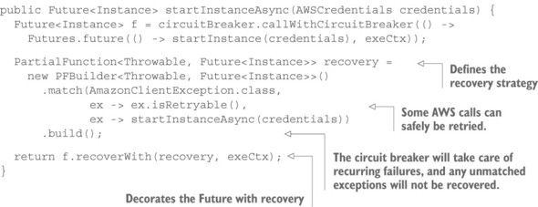
In this fashion, you wrap up the task of instantiating a new worker node such that all failures are registered—tripping the circuit breaker when necessary—and failures that are expected to routinely be fixed by trying again lead to retries. The assumption here is that such failures are complete (no partial success has already changed the system state) and transient. Refinements of this scheme may implement a backoff strategy that schedules retries for progressively delayed points in time instead of trying again immediately. It is easy to see that this would be incorporated by using a scheduler call (for example, using akka.pattern.after[3]), wrapping startInstanceAsync() in the recovery strategy—of course, you do not block a thread from the ExecutionContext’s thread pool by using Thread.sleep().
See http://doc.akka.io/japi/akka/current/akka/pattern/Patterns.html for the Java documentation.
The attentive reader will have noticed that the code listings use the synchronous version of AmazonEC2Client even though there is an asynchronous version as well: AmazonEC2AsyncClient provides a runInstancesAsync() method that accepts a completion callback as its second parameter (the returned java.util.concurrent.Future is not useful for event-driven programming, as discussed in chapter 3). You can use the callback to supply the value for a Promise and thereby obtain a Scala Future in an event-driven fashion.
Listing 14.3. Bridging client methods to execute an Amazon async client
public Future<RunInstancesResult> runInstancesAsync(
                                         RunInstancesRequest request,
                                         AmazonEC2Async client) {
  Promise<RunInstancesResult> promise = Futures.promise();
  client.runInstancesAsync(request,
    new AsyncHandler<RunInstancesRequest, RunInstancesResult>() {
      @Override
      public void onSuccess(RunInstancesRequest request,
                            RunInstancesResult result) {
        promise.success(result);
      }

      @Override
      public void onError(Exception exception) {
        promise.failure(exception);
      }
    });
  return promise.future();
}
Unfortunately, the AWS library implements the asynchronous version in terms of the same blocking HTTP network library that also powers the synchronous version (based on the Apache HTTP client library)—it just runs the code on a separate thread pool. You could configure that thread pool to be the same ExecutionContext you use to run your Scala Futures by supplying it as a constructor argument when instantiating AmazonEC2AsyncClient. That would not be a net win, however, because instead of just wrapping the synchronous call in a Future, you would have to bridge all client methods in the fashion shown in listing 14.3—an overhead of 15–20 lines per API method. The execution mechanics would be the same, but adapting the different asynchronous API styles would involve significant extra programming effort (and, hence, more opportunity for errors). We will take a deeper look at situations like this in section 14.5 when we discuss patterns for managed blocking.
Now that you have started the worker node, you need to also manage the rest of its lifecycle: the execution component needs to keep track of which workers are available, monitor their health by performing regular status checks, and shut them down when they are no longer needed. Performing health checks typically means making service calls that query performance indicators that the service is monitoring internally. The fact that a response is received signals general availability, and the measured quantities can be factored into future decisions about whether to scale the number of worker nodes up or down. The measured quantities can also be indicative of specific problems, such as unusually high memory consumption, that require dedicated reactions (for example, an operator alert or automatic reboot after a diagnostic memory dump).
This brings you to the final step of a worker node’s lifecycle: the execution component needs to instruct the infrastructure to shut down a node. Completing the AWS example, this would be done as follows.
Listing 14.4. Terminating the EC2 instances
public Future<TerminateInstancesResult> terminateInstancesAsync(
                        AmazonEC2Client client, Instance... instances) {
  List<String> ids = Arrays.stream(instances)
                           .map(i -> i.getInstanceId())
                           .collect(Collectors.toList());
  TerminateInstancesRequest request = new TerminateInstancesRequest(ids);

  Future<TerminateInstancesResult> f =
    circuitBreaker.callWithCircuitBreaker(
      () -> Futures.future(() -> client.terminateInstances(request),
                           executionContext)
    );

  PartialFunction<Throwable, Future<TerminateInstancesResult>> recovery =
    new PFBuilder<Throwable, Future<TerminateInstancesResult>>()
      .match(AmazonClientException.class,
             ex -> ex.isRetryable(),
             ex -> terminateInstancesAsync(client, instances))
      .build();
  return f.recoverWith(recovery, executionContext);
}
Of course, you will want to use the same circuit breaker and ExecutionContext as for the runInstancesAsync() implementation in listing 14.4, because it is the same infrastructure service that you are addressing—it is not reasonable to assume that creating and terminating machine instances are independent operations such that one keeps working while the other is systematically unavailable (as in failing to respond, not denying invalid input). Therefore, you place the responsibility for communicating with the infrastructure service in its own execution subcomponent (called the resource pool interface in section 12.3). Although AmazonEC2Client offers a rich and detailed API (we glossed over the creation of security groups, configuration of availability zones and key pairs, and so on), the resource pool need only offer high-level operations like creating and terminating worker nodes. You present only a tailored view of the externally provided capabilities to the components in your system, and you do so via a single component dedicated to this purpose.
This has another important benefit: you not only have encapsulated the responsibility for dealing with the vicissitudes of the external service’s availability, but you can also switch to a completely different infrastructure service provider by replacing this one internal representation. The execution component does not need to know whether the worker nodes are running on Amazon’s Elastic Compute Cloud or Google’s Compute Engine (or whatever computing infrastructure is in vogue at the time you are reading this), as long as it can communicate with the services the worker nodes provide.
Another aspect of this placement of responsibility is that this is the natural—and only—location where you can implement service-call quota management: if the infrastructure API imposed limits on how frequently you could make requests, then you would keep track of the requests that passed through this access path. This would allow you to delay requests in order to avoid a temporary excess that could lead to punitively degraded service—to our knowledge this is not true for AWS, but for other web APIs, such limitations and enforcement are common. Instead of running into a quota on the external service, you would degrade the internally represented service such that the external service was not burdened with too many requests.
To recapitulate, we have considered the management actions that the execution component needs to perform in order to provision and retire worker nodes, and you have placed the responsibility for representing the infrastructure provider that performs these functions in a dedicated resource pool interface subcomponent. Although the mechanism for conveying the requests and responses between the execution component and its worker nodes will change depending on which service frameworks are available over time, the remaining aspect that we need to discuss in the context of the Resource Encapsulation pattern is how to model knowledge about and management of the worker nodes within the execution component.
Each worker node will gather its own performance metrics and react to the failures it can address, but ultimately the execution component is responsible for the currently running workers: it has taken this responsibility by asking the resource pool to provision the workers. Some classes of failures—such as fatal resource exhaustion in terms of CPU cycles or memory—cannot be dealt with from within, and the supervising component needs to keep track of its subordinates and dispose of those that have failed terminally or are otherwise inaccessible. Another way to look at this is that a worker node provides its own service to the rest of the system and is also coupled to a resource that must be managed in addition to the service that the resource powers. This is true in all cases where the supervising component assumes this kind of responsibility by effecting the creation of or by asking for the transfer of ownership of such a resource. As a demonstration of managing a worker node’s underlying resource, the following listing sketches an actor that takes this responsibility.
Listing 14.5. Execution component communicating with an actor as if it were a worker node

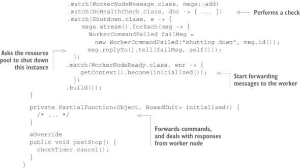
In the spirit of delimited consistency, as discussed in chapter 8, you bundle all aspects of interaction with the worker node in this representation so that the forwarding of messages to and from the worker node can take into account the worker’s lifecycle changes and current health status. With this encapsulation, the execution component creates a WorkerNode actor for every worker node it asks the resource pool to create; then, it only needs to communicate with that actor as it if were the worker node itself. This proxy hides the periodic health check processing as well as the fact that after the instance has been created, it will take a certain amount of time for the worker’s services to start up and signal their readiness to accept commands.
When implementing the WorkerNode class, you need to ask the resource pool to shut down the represented instance. In a full-fledged implementation, you might want to add more features that need to interact with the resource pool: for example, monitoring the instances via the cloud infrastructure provider’s facilities (in listing 14.5, that would be Amazon CloudWatch). This is another reason to place the responsibility for all such interactions in a dedicated subcomponent: otherwise, you would duplicate this code in several places and thereby lose the ability to monitor the availability of the cloud infrastructure service consistently in a single location. Note that this is meant in a logical sense and not necessarily in a physical one: the resource pool interface could well be replicated for fault tolerance, in which case you would not care about synchronizing the state it maintains because losing the circuit breaker’s status in the course of a component crash would not have a large or lasting negative effect.
14.1.3. The pattern, revisited
We have examined the interactions between the execution component and the infrastructure service that provisions the worker nodes, and you have placed all aspects of this interaction in a dedicated resource pool interface subcomponent. It is this component’s responsibility to represent the resource pool to the rest of the system, allowing consistent treatment of the infrastructure provider’s availability and limitations. This encapsulation is also in accordance with the principle of abstracting over the concrete implementation of a potentially exchangeable resource; in this case, you simplify the adaptation to a different cloud infrastructure provider.
The second aspect we have illuminated is that worker nodes are based on dynamically provisioned resources that need to be owned by their supervising component. Therefore, you have placed the responsibility of monitoring the worker node and communicating with it in a WorkerNode subcomponent of the execution component, sketched as an actor for illustration. Although communication with the services provided by a worker node is taken care of by the service fabric or framework, there is a remaining responsibility that cannot be satisfied from within the worker node because it is about the management of the node’s underlying resources.
The Resource Encapsulation pattern is used in two cases: to represent an external resource and to manage a supervised resource—both in terms of its lifecycle and its function, in accordance with the Simple Component pattern and the principle of delimited consistency. One aspect we glossed over is the precise relation of the Worker-Node subcomponents to their execution component parent: should a WorkerNode supervisor be its own component, or should it be bundled with the execution component? Both approaches are certainly possible: the code modularity offered by object-oriented programming can express the necessary encapsulation of concerns just as well as deploying a WorkerNode service instance on the hardware resources that the execution component is using. Spinning up a separate node would again require you to establish a supervision scheme and therefore not solve the problem.[4] The way the decision is made will depend on the case at hand. Influential factors are as follows:
Note that this depends on the service framework used, though, in that automatic resource cleanup in combination with health monitoring may already be provided—meaning this pattern is incorporated at the framework level.
- Complexity of the resource-management task
- Runtime overhead of service separation for the chosen service framework
- Development effort of adding another asynchronous messaging boundary
In many cases, it will be preferable to run the management subcomponents within their parent’s context (that is, to encapsulate this aspect in a separate class or function library). When using an actor-based framework, it is typically a good middle ground to separate resource management into its own actor, making it look and behave like a separate component while sharing most of the runtime context and avoiding large runtime overhead.
14.1.4. Applicability
The Resource Encapsulation pattern is an architectural pattern that mainly informs the design of the component hierarchy and the placement of implementation details in code modules—either reinforcing the previously established hierarchical decomposition or leading to its refinement. The concrete expression in code depends on the nature of the resource that is being managed or represented. The pattern is applicable wherever resources are integrated into a system, in particular when these resources have a life-cycle that needs to be managed or represented.
In some cases, the nature of resources used by the system is not immediately visible: in this section’s example, a beginner’s mistake might be to leave the worker node instances to their own devices after creation, having them shut themselves down when no longer needed. This works well most of the time, but failure cases with lingering but defunct instances will manifest in the form of surprisingly large infrastructure costs, at which point it will become obvious that reliable lifecycle management is required.
14.2. The Resource Loan pattern
Give a client exclusive transient access to a scarce resource without transferring ownership.
A variant of the Resource Loan pattern is widely used in non-Reactive systems, the most prominent example being that of a database connection pool. Database access is represented by a connection object via which arbitrary operations can be performed. The creation of connections is expensive, and their number is limited; therefore, a connection is not owned by client code but is taken from a pool before performing an operation and put back afterward. The connection pool is responsible for managing the lifecycle of its connections, and client code obtains temporary permission to use them. Failures in this scenario are communicated to the client, but their effect on the connection in question is handled by the pool—the pool owns and supervises the connections.
In a Reactive system, you strive to minimize contention as well as the need for coordination: hence, the classic database connection pool usually only features as an internal implementation detail of a component whose data storage is realized by means of a relational database. But you will frequently encounter the use of scarce resources in your systems, and the same philosophy that drives the connection pool abstraction is useful in Reactive system design as well.
14.2.1. The problem setting
Toward the end of the discussion of the Resource Encapsulation pattern, we touched on the possibility of separating the ownership and the use of a resource: not being responsible for supervision aspects frees the user from having to perform monitoring tasks or recovery actions. In the example of the execution component of the batch job service, it may seem extraneous that the WorkerNode subcomponent needs to watch over the physical instance provisioned via the resource pool interface. Would it not be nicer if the resource pool were not merely a messaging façade for talking to a cloud provider but also took responsibility for the lifecycle management of the instances it provisions?
The task: Your mission is to change the relationship between the resource pool interface component and the execution component such that the resource pool will retain ownership of the worker nodes it provides, and the execution supervisor can concentrate on managing the batch jobs.
14.2.2. Applying the pattern
Before we look at this in more detail, we need to establish some terminology. The word loan is often used in a financial context: a lender gives a certain sum to a borrower, who is expected to pay it back later, usually with interest. More generally, this term applies to any asset that can be transferred, with the important notions that ownership of the asset remains with the lender throughout the process and the transfer is temporary and will eventually be reversed. Renting an apartment falls in this category: the landlord lets you live in their property and expects you to vacate it when the lease ends; meanwhile, the landlord stays responsible for the general upkeep of the building and everything that was rented with it. This example also illustrates the exclusivity of the arrangement, given that an apartment can only be rented to one tenant at a time. Therefore, the resource (the apartment, in this case) is also scarce: it cannot be copied or inhabited by multiple tenants independently at the same time. This resource comes at a per-instance cost.
To answer the question of having the resource pool take responsibility for the lifecycle of the instances it provisions, we will consider the worker nodes provisioned by the resource pool interface to be like apartments that the execution component wants to use. It will place a worker in each apartment; the worker will then process batch jobs. A worker node is a potential home for a batch-job process. In this scenario, apartments are provided by the cloud infrastructure, but this is the most basic, empty apartment you can think of—there is nothing interesting in it until someone moves in. The worker node components in the structure of the batch job service correspond to people who need a apartment to live in. Once a worker has moved into an apartment, the execution component can send work items to their address and receive replies from them—business-level information can flow. The missing piece is a kind of concierge who looks after the apartments rented for workers and checks regularly with the property and with the worker to see that everything is in order. This allows the execution component (the work provider) to concentrate entirely on conversations about the work that is to be done; monitoring of the workforce is done by the concierge. The concierge is responsible for ending the lease when a worker moves out, solving the problem of possibly leaking resources.
Switching back from the anthropomorphic metaphor to computer programming, when the execution component asks the resource pool interface for a new worker node, the resource pool uses the cloud infrastructure to provision a new machine instance: for example, using the AWS EC2 API, as shown in the previous pattern discussion. But instead of just returning the instance identifier and network address to the execution component, the resource pool now assumes responsibility for the worker node: it needs to begin monitoring the service by performing regular health checks. The execution component only receives the network address at which the new worker node service is being provided, and it assumes that the resource pool keeps this node in good working condition—or terminates it and provides a new one.
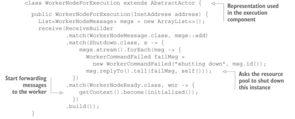
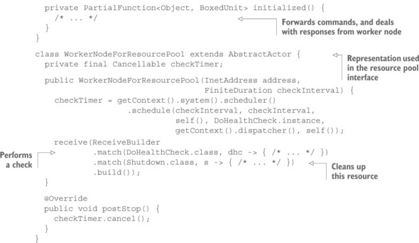
In order to do that, the resource pool must know about the kind of service that is being provided by the worker node: it must be able to ask for the relevant set of performance metrics, and it must understand their meaning to assess a worker node’s fitness. The resource pool interface thus assumes more responsibility than before, and is also more tightly coupled to the function of the resources it provides. Instead of a more-or-less generic representation of the cloud infrastructure API, the pool becomes more specific, tailored to the needs of the batch job service; in return, you achieve a better separation of concerns between the lender and the borrower. The relationship in the previous pattern was that of a manufacturer (the author of WorkerNode) and a buyer (who instantiates a WorkerNode), and the latter’s obligation to perform maintenance led to a coupling that you can, in this case, avoid. In source code, this means you will have WorkerNode representations in the execution component as well as in the resource pool interface component, but these take care of different aspects that were previously mixed within one class.
Listing 14.6. Separating management of the resource from management of tasks
14.2.3. The pattern, revisited
While applying this pattern, you segregate the responsibilities of resource maintenance and use: the execution component asks for the service of a new worker node and gets that back in response without the additional burden that comes with a transfer of ownership. The resource that is loaned in this fashion is still exclusively available to the borrower; the execution component can keep usage statistics, knowing the only jobs that will be processed by the worker node are those the execution component sent. There is no competition for this resource among different borrowers for the duration of the loan.
The price of this simplification of the borrower is that the lender must take over the responsibilities the borrower has shed, requiring the lender to know more about the resource it is loaning. One important point is that this additional knowledge should be kept minimal; otherwise, you violate the Simple Component pattern and entangle the functionalities of lender and borrower more than necessary. This is particularly relevant when different kinds of borrowers enter the picture: the purpose of separating the lender, borrower, and loaned resource is to keep their responsibilities segregated and as loosely coupled as is practical. The lender should not know more about the capabilities of the resource than it needs to perform the necessary health checks; the concrete use of the resource by the borrower is irrelevant for this purpose.
As a counterexample, suppose that instead of loaning the resource, the resource pool interface completely encapsulated and hid the worker nodes, forcing the execution component to go through it for every request the execution component wanted to make. We will discuss this angle in detail later in this chapter, as the Resource Pool pattern. This would entail enabling the resource pool interface to speak the language of a worker node in addition to its own. By loaning the resource, the borrower may use it in any way necessary, but unbeknownst to the lender, who is freed from the burden of having to understand this interaction. Consider the following possible conversation for a job execution:
- Execution sends job description to Worker Node.
- Worker Node acknowledges receipt and starts sending regular execution metrics.
- Execution may ask for intermediate results on behalf of end user (for example, for a live log file viewer).
- Worker Node replies with intermediate results when asked.
- Worker Node signals job completion when done.
- Execution acknowledges receipt and relieves Worker Node from this job.
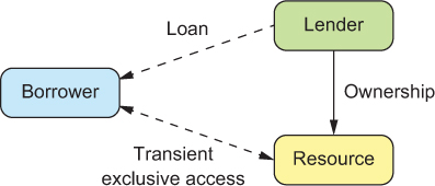
The individual messages that are exchanged are small building blocks from which this interchange is built. The purpose of the Resource Loan pattern is to allow the lender to be largely unaware of this protocol, which is only shared by the borrower and the resource, as shown in figure 14.1.
Figure 14.1. The relationship between lender, borrower, and resource in the Resource Loan pattern. The goal is to facilitate efficient exchange between borrower and resource while placing the burden of ownership with the lender.
14.2.4. Applicability
This pattern is applicable wherever a resource needs to be used by a component whose genuine responsibility does not a priori include the monitoring and lifecycle management of that resource. If the aspects of provisioning, monitoring, and disposal can be factored out into their own component, then the resource user is effectively freed from the details of these concerns: it is not forced to take on these incidental responsibilities.
When deciding this question, it is important to require the resulting resource manager component to be nontrivial. Factoring out the management of a trivial resource only leads to additional runtime and design overhead; every component that is split out should be considered to have a basic cost that needs to be offset by the benefits of the achieved decoupling and isolation.
14.2.5. Implementation considerations
In the example, the execution component is in full control of the worker nodes, and the questions of how long to use them and when to shut them down are decided at its sole discretion. This will need to change if you assume that the underlying computing resource is scarce and may need to be vacated in response to external events (for example, when the per-minute runtime cost rises above a certain threshold). The execution component will in this case only formulate the desired number of worker nodes, and the decision about how many are provisioned will be made by the resource pool interface. We can also envision worker nodes being reallocated to different execution components for separate compute clusters.
This scenario requires that the resource lender retain the power to forcefully take back resources when needed. If it handed the borrower a direct reference to the loaned resource, the borrower could hold on to that reference and keep using it after the loan was withdrawn. The solution is to hand out a proxy instead of the resource. This is easily possible in a setting where service references are location transparent, because the borrower does not care or know about the precise routing of requests to the resource. The proxy must be able to forward requests and responses between the borrower and the resource, and it also must obey a deactivation command from the lender, after which it rejects all requests from the borrower. In this fashion, the lender can cut the resource loose from the borrower as required and decommission or reallocate the resource without interference from unruly borrowers.
Another consideration is that a resource that has been loaned to another service instance should be returned when the borrower terminates. Otherwise, the lender may not notice that the resource is no longer being used—it may stay around, healthy and fully functional, for a long time. Failing to recognize this situation amounts to a resource leak.
14.2.6. Variant: using the Resource Loan pattern for partial exposure
The mechanics for handing out a subcomponent to an external client can also be used to expose part of a component’s functionality or data. Imagine a component that holds a large, multidimensional array of floating-point numbers resulting from the analysis of a huge amount of data. Clients may be interested in particular slices of the array but are not allowed to make changes. Using the Resource Loan pattern, the component can offer a protocol for obtaining a handle to a particularly shaped slice of the data for read-only access. The client invokes methods on this handle to obtain particular values, wrapped in a Future. This allows the implementation to decide how many of the referenced values to ship to the client immediately and how to retrieve the rest when the client eventually asks for them—imagine a slice big enough to cause considerable network usage if it were transferred up front.
By using the Resource Loan pattern, the component that manages the multidimensional array knows exactly how many read-only handles are currently active, and it can invalidate them when needed. For example, only a limited number of snapshots can be kept in memory—with clients having handles to them—and when further changes need to be made, the oldest snapshot will be retired to free up its space.
14.3. The Complex Command pattern
Send compound instructions to the resource to avoid excessive network usage.
You have encapsulated the resources your system uses in components that manage, represent, and directly implement their functionality. This allows you to confine responsibility not only for code-modularity reasons (chapter 6) but also for vertical and horizontal scalability (chapters 4 and 5) and principled failure handling (chapter 7). The price of all these advantages is that you introduce a boundary between the resource and the rest of the system that can only be crossed by asynchronous messaging. The Resource Loan pattern may help to move a resource as close as possible to its users, but this barrier will remain, leading to increased latency and, usually, decreased communication bandwidth. The core of the Complex Command pattern lies in sending the behavior to the resource in order to save time and network bandwidth in case of loquacious interchanges between resource and users; the user of the resource is only interested in the comparatively small result.
This pattern has been used for this purpose for a long time. We will approach it by way of a common example. Consider a large dataset, so large that it cannot possibly fit into the working memory of a single machine. The data will be stored on a cluster of machines, each having only a small fraction of the data—this is known as big data. This dataset is a resource that will be used by other parts of the system. Other components that interact with these data will send queries that have to be dispatched to the right cluster nodes according to where the data are located. If the data store only allowed the retrieval of individual data elements and left it to the clients to analyze them, then any summarizing operation would involve the transfer of a huge amount of data; the resulting increase in network usage and the correspondingly high response latency would be exacerbated by more-complex analyses requiring frequent back and forth between the client and the data source. Therefore, big data systems work by having the user send the computation job to the cluster instead of having the computation interrogate the cluster from the outside.
Another way to think of this pattern is to picture the client and the resource (the large dataset) as two nations that are about to negotiate a contract. To facilitate an efficient exchange, an ambassador (the batch job) is sent from one nation to the other. Negotiations may take many days, but in the end the ambassador comes home with the result.
14.3.1. The problem setting
We can generalize this problem as follows: a client wants to extract a result from a resource, a value that is relatively small compared to the quantity of data that need to be moved in the course of the loquacious exchange required to obtain that value. The computation process is more intimately coupled with the data than with the client component that initiates it; the client is not genuinely interested in how the data are processed, as long as it gets the result. The resource, on the other hand, only holds the data and does not know the process by which the client’s requested result can be extracted. Therefore, the process description needs to be sent from the client to the resource; the client needs to be provided with this description by the programmer, who presumably knows both the need and the structure of the data.
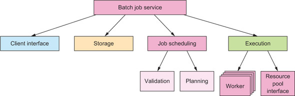
This is precisely what a batch job service is all about. You need to amend your mental picture slightly: the graphical overview has not changed from section 12.2, but we repeat it in figure 14.2 as a refresher. The worker nodes are no longer stateless services that can be provisioned and decommissioned dynamically; instead, there is a fixed set of worker nodes in the big data cluster, and each persistently holds the partition of data it has been entrusted with. The execution component will take care of sending jobs to the correct worker nodes according to the data the jobs need, which in turn will have an influence on how scheduling decisions are made. These consequences—although interesting—are highly dependent on the particular example chosen. More illuminating in terms of the generic pattern is the question of what constitutes a batch job and how it is executed by a worker node. You will see in this section that there is more than one answer.
Figure 14.2. The component hierarchy of the batch job service as derived in section 12.2
14.3.2. Applying the pattern
We will start by considering the essential pieces that need to be conveyed. In order to route the job to the correct nodes, you need to know which data will be needed; the dataset descriptor will thus need to be part of the batch job definition. The Scheduler component will have to inspect this information and factor it into its decisions, which is to say it only needs to read and understand this part. The execution component, on the other hand, must split the job into pieces according to the partitioning of the data: in addition to reading and understanding the dataset descriptor, it will need to be able to create copies of the overall batch job that act on subsets of the data, to be executed by the individual worker nodes.
Another approach would be to always send the full job description and have the worker node ignore all parts of the dataset that it does not have, but this would be problematic if the distribution of data changed or data partitions were replicated for fault tolerance: without making the data selection consistently at one location, it would be difficult or impossible to guarantee that, in the end, every requested data element was processed exactly once. Sending the narrowed-down selection to the worker nodes gives them unambiguous instructions and allows them to signal that some of the requested data are no longer available at their location.
This leads you to the conclusion that a batch job must be a data structure that can be constructed not only by the client but also by the batch service’s components. The first part of the data that it contains is a dataset descriptor that several batch service components will need to understand and possibly split up.
The second piece of information that must be conveyed is the processing logic that acts on the selected data. For this purpose, the batch job must describe how this logic consumes the elements of the dataset and how the resulting value is produced in the process. The last piece is then a recipe for combining the partial results from the individual worker nodes into the overall result that is shipped back to the external client.
Using the platform’s serialization capabilities
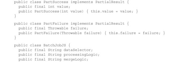
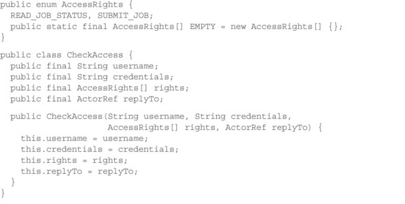
Neglecting all incidental information such as client authentication, authorization, quota, priority management, and so on, the essential structure of a batch job is captured in the following class definitions: the batch job has a selector to identify data to process, some processing logic to create partial results, and merge logic to combine the partial results.
Listing 14.7. The essence of a batch job
public interface ProcessingLogic {
  public PartialResult process(Stream<DataElement> input);
}

public interface MergeLogic {
  public Result merge(Collection<PartialResult> partialResults);
}

public class BatchJob {
  public final String dataSelector;
  public final ProcessingLogic processingLogic;
  public final MergeLogic mergeLogic;

  public BatchJob(String dataSelector,
                      ProcessingLogic processingLogic,
                      MergeLogic mergeLogic) {
    this.dataSelector = dataSelector;
    this.processingLogic = processingLogic;
    this.mergeLogic = mergeLogic;
  }

  public BatchJob withDataSelector(String selector) {
    return new BatchJob(selector, processingLogic, mergeLogic);
  }
}
The data selector is assumed to have a String-based syntax for the sake of simplicity—describing datasets is not the primary focus of this pattern—and a copy constructor is provided by way of the withDataSelector() method so that the execution component can derive jobs that act on subsets of the data.
The more interesting piece that we will now examine in greater detail is the logic that is conveyed, represented here as two interfaces for which the client will need to provide implementations. ProcessingLogic describes how to compute a partial result from a dataset that is represented as a stream[5] of elements: you potentially are dealing with big data that do not fit into memory all at once, so passing the full Collection<DataElement> into the processing logic could easily lead to fatal working-memory exhaustion (an OutOfMemoryError in Java). MergeLogic then takes the partial results and combines them into the overall result that the client wants; here, you expect the involved amount of data to be relatively small—even thousands of partial results should not take up a large amount of memory, because you are working under the assumption that the result value is much smaller than the analyzed dataset.
In order to send a BatchJob message from the client to the batch job service, you need to serialize this Java object. In listing 14.7, you could add extends Serializable in a few places and add some serialVersionUID values, with the result that the Java Runtime Environment (JRE) would be able to turn a BatchJob object into a sequence of bytes that could be transferred. On the other end—within the batch job service—you would need to reverse that process, but here you hit a snag: the JRE can only deserialize classes whose definition it already knows about. The serialized representation contains only the class names of the objects that are referenced and the serialized form of the primitive values they contain (integers, characters, arrays); the bytecode that describes the behavior of the objects is missing.
In order to transfer that, you will have to add the corresponding vocabulary to the protocol between the batch service and its clients. They will have to upload the JAR[6] files in conjunction with the job so that the necessary class definitions can be made known wherever a BatchJob message needs to be interpreted. This can be a tedious and brittle undertaking where any forgotten class or wrong library version leads to fatal JVM errors that make it impossible to run the job. Also, note that this approach ties both clients and service together in their choice of runtime environment: in listing 14.7, both parties need to use compatible versions of the Java Runtime in order to successfully transfer and run the bytecode as well as the serialized objects. Using the batch job service from a client written in JavaScript, Ruby, Haskell, and so on would not be possible.
Java archive: basically, compressed files containing the machine-readable class definitions of a library, organized in class files.
Using another language as a behavior transfer format
Another way to look at this is that the batch job service defines a language choice that is implicit to its client interface protocol. Batch jobs must be formulated such that the service can understand and execute them. You can turn this around to exercise greater freedom in this regard: if the service—still written in Java—were to accept the processing logic in another language, preferably one that is widely used and optimized for being shipped and run in a variety of environments; then, you could sidestep the tight code coupling you faced when transferring Java classes directly. There are several options in this regard, including JavaScript, due to its ubiquity and ease of interpretation; and Python, due to its popularity for data analytics purposes. The Java 8 Runtime includes a JavaScript engine that you can readily use to demonstrate this approach.
Listing 14.8. Executing processing logic by invoking the Nashorn JavaScript engine

The processing logic is passed as a trivially serializable String containing a JavaScript text that defines a process() function when it is evaluated. This function is then invoked with the stream of data elements and expects a Result back. A simple example of a processing logic script could look like this:
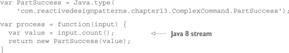
This code is available in the source code archives at www.manning.com/books/reactive-design-patterns and on GitHub if you want to play around with embedding Java-Script parts in your Java applications.
One concern you will likely encounter with this technique is that the submitted logic may be implemented using other libraries that simplify the job. Consider, for example, the DataElement that contains an image to be analyzed. Assuming that the analysis job is written by someone who likes the hypothetical image-manipulation library Gimp JS, the job script will need this library to be present when the job is executed. This could be achieved by providing this library in the execution environment as part of the batch service’s contract, or the library’s code could be included with the job script. The former approach saves resources, and the latter gives you more freedom in terms of which version of which library to use.
To recapitulate, we have explored two ways of transferring behavior—the processing logic—from client to batch service, one tied to the Java language and Runtime and one in terms of a different language. The latter is used as a behavior-exchange format that may be foreign to both parties but has the advantage of being easily transferable and interpretable. What we have not considered so far are the security implications of letting clients submit arbitrary processing instructions to your big data cluster—although they are meant to only analyze heaps of data, they are capable of calling any public method in the JRE, including file system access, and so on.
In order to secure your cluster, you could implement filters that inspect the submitted code (hairy to get right in terms of not rejecting too many legitimate jobs); you could restrict the script interpreter (hairy in terms of not rejecting all malicious jobs); or you could use a behavior-exchange format that can only express those operations that you want to expose to clients. Only the last option can deliver in terms of security and safety, but the price is high because most readily available languages are intended for general purpose use and are therefore too powerful.
Using a domain-specific language
Note
This section describes techniques that are very powerful but require deeper knowledge and greater skill than is available to beginners. If you do not fully understand how the presented solutions work, you can still keep their features in mind as an inspiration for what is possible.
Pursuing the first two options mentioned at the end of the previous section is specific to the example chosen and leads you to acquire an intimate knowledge of JavaScript. The third option is of more general value. To go down this path, you need to devise a domain-specific language (DSL). As Debasish Ghosh discusses in DSLs in Action (Manning, 2011), there are two basic forms of such languages:
- Internal DSL— Embedded and expressed in the syntax of a host language
- External DSL— Stands on its own
Designing an external DSL involves creating its grammar, implementing a corresponding parser in the language from which the DSL will be used, and, typically, also creating some tooling to validate or otherwise automatically process documents in this language. The advantage of an external DSL is that it is not encumbered by the syntactic rules of a host language: it can be designed with complete freedom. Imagine a big data language that describes the stepwise treatment of the input, as follows.
Listing 14.9. External DSL using different syntax than the host language

Evaluating this script would iterate over the dataset twice: first to find the median price for cars from the 1950s and then to collect all pairs of make and model that cost more than the median. The code shown would be the serialized form of the program; by restricting the allowed commands, you can exercise tight control over what client code can do. The worker node parses such scripts into a syntax tree and either interprets it directly or compiles it into an executable program for the platform it is running on—in the Java example, this would typically mean emitting bytecode that corresponds to the process described in the DSL. The latter is needed only when the DSL includes constructs like loops, conditionals, and recursions that lead to a high volume of interpreted expressions; in this example, interpretation of the given statements would consume a negligibly small amount of CPU cycles compared to the actual computation being carried out over a large dataset.[7]
The only part that would need to be interpreted for each data element is the formula used to select cars by year. Everything else lends itself to being offered as a prepackaged compound operation.
If complete freedom of expression is not of primary importance, an internal DSL may be a better fit—constructing and maintaining a parser and interpreter for a custom language adds considerable development effort and organizational overhead, not to mention that designing a language that is reasonably self-consistent is a talent not every engineer is gifted with. As an example of an internal stream-processing DSL, consider the Akka Streams library: the user first creates a Graph—an immutable, reusable blueprint for the intended processing topology—and then materializes that to be executed, typically by way of a group of Actors. You can separate these two steps so that the Graph is created at the client, serialized, submitted to the batch service, and finally deserialized and executed on the worker node. Defining a Graph corresponding to the external DSL in listing 14.9 could look like this.
Listing 14.10. Internal DSL
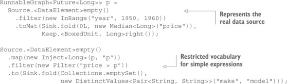
Normally, the map, filter, and fold operations will accept any function literal (lambda expression) that you provide, and syntactically that would be valid here as well. Using arbitrary code would bring you back to the problem of having to transfer the user’s bytecode to the batch service, though, which is why this example provides a restricted vocabulary that is guaranteed to be known by the batch service’s worker nodes. The operations you offer can be compound ones like the median calculation here: you place this element in a data sink that folds the incoming elements with the provided function, starting at the initial value (0L). Behind the scenes, the Graph layout is recorded with the objects you provide so that you can inspect the Graph in order to serialize it—when you encounter the Median object in the position of a folding function, you know you can transfer this behavior to the worker node. The only information you serialize in addition to the operation name is the field name for which the median is to be calculated. You can see a sketch of the necessary class definitions in the source archives.
The same principle applies to the filtering steps, where you may have prepackaged operations like InRange that are configured with a field name, a minimal, and a maximal permissible value. You can also combine this approach with an external DSL, as shown in the case of the generic Filter operation in listing 14.10; implementing a parser and an interpreter for simple mathematical expressions is not as complex as for a full-featured language and is general enough to be reusable across projects.
The approach shown here works best if the Akka Streams library is present on both ends, which saves you the effort of creating the basic Graph DSL infrastructure and the stream-processing engine. You just have to provide the specific operations to be supported. If more flexibility is needed, then the serialization format chosen for these Graphs[8] can serve as an external DSL for client implementations that are not based on the JVM or want to use a different code representation for the processing logic.
Akka Streams does not offer serialization of Graphs at the time of writing (version 1.0).
14.3.3. The pattern, revisited
We started from the premise of sending the behavior to the resource in order to save time and network bandwidth in the case of loquacious interchanges between the two. The resource user is only interested in a comparatively small result. Exploring the possibilities, we found several solutions to this problem:
- If the user and the resource are programmed for the same execution environment, you can write the behavior directly in the same language as the user code and send it to the resource. Depending on the choice of execution environment, this can incur considerable incidental complexity—in the case of Java classes, you would, for example, need to identify all required bytecode, transfer it, and load it at the receiving end. Note that the choice will be hard to revert later, because the implied behavior-exchange format is coupled tightly to the runtime environment.
- To overcome the limitations of directly using the host language, you can choose a different language as your behavior-transfer format, picking one that is optimized for being transferred to remote systems and executed there. We looked at JavaScript as an ubiquitous example of this kind that has also been supported directly by the JRE since version 8.
- If security is a concern, then both previous solutions suffer from being too expressive and giving the user too much power. The resource would execute foreign behaviors that can do absolutely anything on its behalf. The best way to secure this process is to restrict what users can express by creating a DSL. This can be external, with full freedom in its design but correspondingly high cost; internal, reusing a host language; or even another internal DSL, as shown with the Akka Streams library.
In the example, a second piece of information needs to be conveyed from the user to the resource: the dataset the batch job will process. This is not a general characteristic of this pattern; the behavior that is sent to the resource may well have the power to select the target of its operations. Such routing information is typically relevant only within the implementation of the resource; in the case of a DSL-based behavior description, it is usually possible to extract the needed selectors from the serialized behavior.
14.3.4. Applicability
The Complex Command pattern provides decoupling of user and resource: the resource can be implemented to support only primitive operations, whereas the user can still send complex command sequences to avoid sending large results and requests over the network in the course of a single process. The price is the definition and implementation of a behavior transfer language. This has a high cost in terms of development effort, independent of whether you use the host language and make it fit for network transfer, choose a different language, or create a DSL—particular care is needed to secure the solution against malicious users where required.
The applicability of this pattern is therefore limited by the balance between the value of the achieved decoupling and network bandwidth reduction in the context of the project requirements at hand. If the cost outweighs the benefits, then you need to pick one:
- Provide only primitive operations to make the resource implementation independent of its usage, at the cost of more network round trips.
- Implement compound operations that are needed by the clients within the protocol of the resource, to obviate the need for a flexible behavior-transport mechanism.
The first option values code modularity over network usage, and the second does the reverse.
14.4. The Resource Pool pattern
Hide an elastic pool of resources behind their owner.
So far, we have discussed the modeling and operation of a single resource as well as its interaction with its clients. The astute reader will have noticed that something is missing from the full picture: the core principles of Reactive system design demand replication. Recalling the discussion from chapter 2, you know that resilience cannot be achieved without distributing the solution across all failure axes—software, hardware, human—and you know that elasticity requires the ability to distribute the processing load across a number of resources that are dynamically adjusted to the incoming demand.
In chapter 13, you learned about different ways to replicate a component. The effort put into this mechanism depends greatly on how much the component’s state needs to be synchronized between replicas. This pattern focuses on the management and external presentation of the replicas. In keeping with the reasoning presented in chapters 4 and 5, it relies heavily on asynchronous message passing and location transparency to achieve scalability.
14.4.1. The problem setting
The example that readily offers itself is the batch job service you have been building and enhancing in the previous chapters. Although the overall system implements a more complicated resource pool, with sophisticated scheduling of complex commands (batch jobs), the execution component offers a simple, pure example of a resource pool: after the Scheduler component has decided the order in which upcoming jobs will be run, the execution component picks them up and assigns them to worker nodes as they become available—either by finishing their previous work or by being provisioned in response to rising demand.
Instead of investigating the details of how the relationship between the Scheduler component, the execution component, and the worker nodes is represented in code, we will focus on the messaging patterns that arise between these components: in particular, lifecycle events for worker nodes and the execution component. This will illuminate their relationship in a fashion that is more easily applied to other use cases.
14.4.2. Applying the pattern
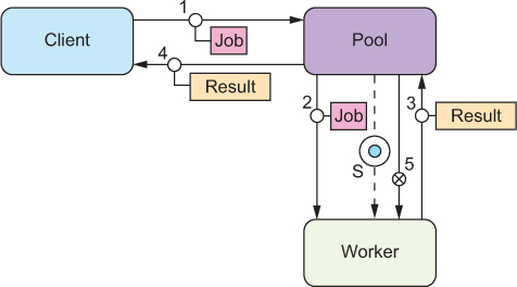
The part of the batch job service that we are looking at is the logic in the execution component that distributes incoming batch jobs to available worker nodes. The jobs have previously been pulled from the schedule that is published by the Scheduler component. The basic process assumed so far is shown in figure 14.3, using the conventions for diagramming Reactive systems that are established in appendix A.
Figure 14.3. The client represents the source of the batch jobs, which is the part of the execution component that has pulled the jobs from the published schedule. The pool is the subcomponent that creates, owns, and supervises the worker nodes. Ignoring the fact that multiple workers may collaborate on one job, the basic flow sends the job to the worker and conveys the result back to the client.

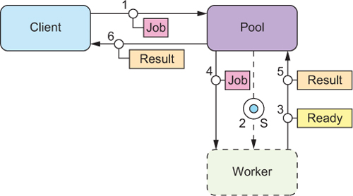
Using this messaging topology, the pool stays in control of all aspects of the workers’ lifecycle: it sends the jobs, gets back the results, creates and terminates workers—the pool always knows the current status of a worker node. Creating a new worker typically happens in response to work being available; the process is depicted in figure 14.4.
Figure 14.4. Compared to the previous process, you insert steps 2 and 3 to create the worker (using the infrastructure service as discussed for the Resource Encapsulation pattern) and await its readiness.
Although this message flow represents the working principle, it should not be taken too literally: the job that triggers the creation of the new worker node may be handed to a different worker than the one being created, especially if it takes a long time to provision the worker node. The new worker then gets the next job dispatched after it signals readiness to the pool; in this sense, readiness is the same as sending back a result for the implied job of being started up.
During periods of reduced processing load, the pool will notice that worker nodes are idle. Because the pool knows how much work it distributes and which fraction of nodes are idle, it is also in a good position to decide when to shut down a node. The corresponding message flow diagram is shown in figure 14.5.
Figure 14.5. After the worker has finished processing a job, the pool sends the termination signal and refrains from sending further jobs to that worker. There can be a sizable delay between messages 4 and 5 to implement an idle timeout.
The final aspect of the worker’s lifecycle is how to handle failures. The pool should monitor all worker nodes by performing periodic health checks[9] and possibly also asking for progress updates. When a worker fails while processing a job, the pool either sends this failure back to the execution component to be recorded and relayed to the external client or retries the job by giving it to another worker. The recovery process for the failed worker depends on the requirements of the use case. The preferable approach is described in the Let-It-Crash pattern: decommission the worker and all of its resources, and provision a fresh one. When a worker fails while idle, only the recovery process needs to be performed.
This functionality may be included in the services framework that is being used.
The message flows you have seen so far all assume that the worker node receives a job in a single message and replies with a result that again fits in a single message. This covers a broad range of services but nowhere near all of them, notable exceptions being streaming services that provide a response that is a priori not bounded, and services where the purpose is the transmission at a given rate so the external client can process the data as they arrive without having to buffer them. Another exception discussed with the Resource Loan pattern is that the external client may reserve a worker and engage in an ongoing conversation with it to perform a complex task.
Accommodating these usage patterns requires a slight reinterpretation of the basic message flow, as shown in figure 14.6. Variants of this flow send all messages between worker and external client (step 5) via the intermediary that represents the client for the pool, or do not signal completion from the worker and instead have the external client convey this signal via the same route taken by the job description. The former allows tighter control over which protocols are permitted between external client and worker, whereas the latter gives the pool more detailed information about when workers are finishing their jobs.
Figure 14.6. In response to the job-request message, the pool will allocate a worker node and inform that node about the work to be done. Concurrently, a message containing the worker’s identity is sent to the external client. The order of these two messages is not important, which is why they share sequence number 3 in the figure. The external client can engage directly with the worker until the job is finished; the worker then signals to the pool and thereby becomes eligible for further work.

The important notion is that you retain the same processes for the creation and termination of worker nodes by keeping the same basic message-flow structure between pool and worker. The pool initiates the work, and the worker eventually replies with a completion notification.
14.4.3. The pattern, revisited
To recapitulate, we have illuminated the relationship between a resource pool and the individual resources it owns by sketching their primary message flows. A resource pool is free to allocate resources or dynamically adjust their number because it is in full control of the resources, their lifecycle, and their use. How the resources are used depends on the pattern applied by external clients:
- The basic model is that a request is sent to the pool and a resource is allocated for the duration of this request only.
- To transfer a large volume of data or messages in the course of processing a single request, the resource can be loaned to the external client for direct exclusive access. All aspects of the Resource Loan pattern apply, including the possibility to employ proxies to enforce usage limitations.
- If the purpose of a loquacious exchange is only the extraction of a relatively small result value, the Complex Command pattern can be used to avoid the overhead of loaning the resource to the external client.
Another consideration is that the basic message flow we discussed involves a full round trip between resource and pool to signal the completion of a request and obtain the next one. This is the most precise, predictable model, and it makes sense where the time to process a request is much larger than the network round-trip time. Under different circumstances, it will be beneficial to use a buffering strategy, where the pool keeps multiple requests in flight toward a single resource and the resource processes them one by one. The results that the resource sends back allow the pool to keep track of how many requests are currently outstanding and limit that number.
A drawback of the queuing solution is that sending a request to a resource that is not currently free means processing may be deferred unpredictably. An SLA violation for one request then has a negative impact on some of the following requests as well. Queueing also means that, in case of a failure, multiple requests may need to be dispatched to be retried (if appropriate).
In the introduction to this pattern, we cited elasticity as well as resilience as motivations for replicating a resource; so far we have only considered the former. The latter is more troublesome due to the ownership and supervision relationship between the pool and its resources: if the pool fails, then the resources are orphaned. There are two ways to deal with this: you can replicate the pool, including its resources—running complete setups in different data centers, for example; or you can replicate only the pool manager and transfer ownership of resources in order to realize a failover between them. Ownership transfer can only be initiated by the current owner if it is still functioning; otherwise, each resource must monitor the pool it belongs to[10] and offer itself to a new owner upon receiving a failure notification for its parent.[11] To replicate the pool manager, any of the replication schemes discussed in the previous chapter can be used, chosen according to the requirements of the use case at hand.
This should typically be implemented by the services framework in a generic fashion.
Readers fluent in Akka will notice that reparenting is not supported for Actors, but we are talking about a pool of resource components in general and not Actors that encapsulate resources. The service abstraction we are referring to here is a higher-level construct than the Actor model.
14.4.4. Implementation considerations
This pattern may be implemented by the services framework: deployment of a resource includes replication factors or performance metrics for dynamic scaling, and looking up that resource results in a resource pool proxy that is interposed between client and resource implicitly. This works without central coordination of the pool proxies generated at the lookup site if the resource either is stateless (just offers computation functions) or uses multiple-master replication. In these cases, there can be one proxy per dependent service instance, removing any single point of failure. A potential difficulty with this is that it assumes the resources handle incoming requests from multiple sources. This can be challenging in the context of applying the Resource Loan pattern or the Complex Command pattern, because requests may be delayed in a less controlled fashion than if a central authority distributes them.
14.5. Patterns for managed blocking
Blocking a resource requires consideration and ownership.
In the example code for how the execution component in the batch job service provisions new worker nodes, you have already encountered the situation that an API you are using is designed to block its calling thread. In the case of the AWS API, there are ways around that, but this is not always the case. Many libraries or frameworks that you may want to or have to use do not offer the option of event-driven interaction. Java Database Connectivity (JDBC)[12] is a well-known example that comes to mind. In order to use these APIs in a Reactive system component, you need to take special care to properly manage the resources that are implicitly seized, most notably the threads required for their execution.
Java Database Connectivity (http://docs.oracle.com/javase/8/docs/technotes/guides/jdbc), part of the Java platform, is a generic access layer for relational databases by which applications are decoupled from the specific database implementation that is used. It is a standard mechanism to provide data sources through dependency injection in application containers, usually driven by external deployment configuration files.
14.5.1. The problem setting
Consider a component that manages knowledge in a fashion that translates well into a relational database model—this may be a booking ledger, user and group management, the classic pet shop, and so on. In the batch service example, this may occur in the authentication and authorization service that the Client Interface component uses to decide whether a given request is legitimate. You could write this component from scratch, modeling every domain object as a persistent actor, or you can reuse the enormous power that is conveniently available through off-the-shelf database management systems. In the absence of good reasons to the contrary, it is preferable to reuse existing working solutions, so you will use a JDBC driver in your implementation based on Java and Akka actors.
The problem you are facing is that executing a database query may take an arbitrary amount of time: the database may be overloaded or failing, the query may not be fully optimized due to a lack of indices, or it might be a very complex query over a large dataset to begin with. If you execute a slow query in an Actor that runs on a shared thread pool, that thread will effectively be unavailable to the pool—and thereby to all other actors—until the result set has been communicated back. Other actors on the same thread pool may have scheduled timers that may be processed only with a large delay unless enough other threads are available. The bigger the thread pool, the more such blocking actions it can tolerate at the same time; but threads are a finite resource on the JVM, and that translates into a limited tolerance for such blockers.
14.5.2. Applying the pattern
The source of the problem is that a shared resource—the thread pool—is being used in a fashion that is violating the cooperative contract of the group of users. Actors are expected to process messages quickly and then give other actors a chance to run: this is the basis for their efficient thread-sharing mechanism. Making a resource unavailable to others by seizing it means the Actor that blocks the thread claims exclusive ownership, at least for the duration of the database query in this example. You have seen for the Resource Loan pattern that the owner can grant exclusive access to another component, but that must always happen explicitly: you must ask the owner for permission.
A thread pool usually does not have a mechanism for signaling that a given thread is being blocked exclusively for the currently running task.[13] If you cannot ask the owner of a shared thread for permission, the logical conclusion is that you need to own a thread on which you can run the database query. This can be done by creating a private thread pool that is managed by the actor: now you can submit the blocking JDBC calls as tasks to this pool.
An exception is the ForkJoinPool, which can be informed using ForkJoinPool.managedBlock() (see https://docs.oracle.com/javase/8/docs/api/java/util/concurrent/ForkJoinPool.ManagedBlocker.html). But in this case, management of the additionally created threads is also limited.
Listing 14.11. Maintaining a private ExecutorService

One peculiarity of JDBC connections is that in order to fully utilize the computation power of a database server, you typically need to create multiple connections so the server can work on several queries in parallel. For this reason, you create a thread pool of the desired poolSize—one thread per database connection—and submit tasks to it as they come in without keeping track of the number of running queries. When the incoming load increases, there will be a point at which all threads in the pool are constantly active; because the number of threads equals the number of database connections, all of those will be active as well. At this point, new requests will start queuing up. In this example, you do not manage this queue explicitly in the actor but instead configure the thread pool with a queue of limited capacity. Tasks that cannot be executed right away because all threads are busy will be held in this queue until threads finish their current work and ask for more. If a task is submitted while the queue is full, its execution will be rejected; you use this mechanism to implement the bounded queuing behavior that is necessary to fulfill the responsiveness of Reactive components, as discussed in chapter 2.
Because the required bounded queue is already implemented by the thread pool, you are free in this example to send the response back to the client directly from the database query task: no interaction with the AccessService is needed on the way back. If you need to keep this actor in the loop, you will send the database result to the actor and have it send the final response to the original client. A reason for doing this might be that you need to explicitly manage the internal request queue—for prioritization, ability to cancel, or some such—or that the database result is only one of several inputs that are needed to compose the final response. Having the queries as well as responses go through the actor in general allow it to comprehensively manage all aspects of this process: the only way to manage a unit effectively is to have exactly one person responsible and keep that person fully informed.
14.5.3. The pattern, revisited
In the example, you have performed multiple steps:
- You noticed that the use case required a resource that was not immediately obvious. Resources are often represented by objects in the programming language that are explicitly passed around or configured, but there are implicit resources that are always assumed and rarely considered explicitly—like threads or working memory—because they are usually shared such that the system works well in most scenarios, by convention. Whenever you run into one of the corner cases, you will need to make these resources explicit in your system design.
- Having recognized the resources that you need to perform a certain function, you modeled them explicitly: in the example, these are the thread pool and the database connection pool. The thread pool is configured with a given number of threads and a maximal submission queue length in order to place an upper bound on the amount of auxiliary resources that are used by it. The same goes for the database connection pool, whose configuration we left out of the example code.
- In keeping with resource encapsulation, you placed the management of these resources in one component, represented by an actor. The lifecycle of the resources is contained within the lifecycle of the actor. The thread pool is created when starting and shut down when stopping. The database connections are managed individually on a per-request basis, taking care to obtain them such that they are released independently of how the processing ends. This is inspired by Let-It-Crash thinking in that shutting down the thread pool will release all associated resources, including the currently used database connections.
- The last step implements the Simple Component pattern, in that the responsibility of the component you are developing is to provide authorization information for users based on their credentials. Toward this end, you need resources and the logic that uses them, all bundled up in one component that does only its job but does it in full.
Although many APIs are widely employed that make implicit use of hidden resources like the calling thread, you will see this pattern used to manage the blocking of threads: hence, the name. The term managed blocking first became known to us when it was used in the ForkJoinPool developed for Java 7, although it was mentioned in the .NET ecosystem several years earlier. ForkJoinPool is not intended as a generic executor but rather as a targeted tool to help the parallelization of tasks that operate on large collections of data, splitting up work among the available CPUs and joining the partial results together. Managed blocking support is needed to keep the CPUs busy while certain threads are stalled, waiting for I/O (from network or disk). Therefore, entering a managed-blocking section will, roughly speaking, spawn a new worker thread that continues the number crunching while the current thread becomes temporarily inactive.
You can generalize this pattern such that it is more widely applicable by considering any kind of resource that needs to be blocked as well as allowing for tailored management strategies of the blocked resource. An example could be the explicit management of a segregated memory region that is split off from the main application heap in order to both place an upper bound on its size and explicitly control the access to this resource—using normal heap memory is unconstrained for all components in the same process and means one misbehaving party can hamper the function of all of them. Another angle is that managed blocking is similar to the Resource Loan pattern in the case of resources that are already encapsulated as Reactive components.
14.5.4. Applicability
The first step of this pattern—investigating the use of hidden resources in ways that violate their sharing contract—should always be applied. Failure to recognize such a case will lead to scalability issues or application failures through resource exhaustion (such as OutOfMemoryError), as we have frequently encountered in consulting engagements.
On the other hand, it is important not to get carried away and claim exclusive ownership of resources at a too fine-grained level or in cases that could live with having only shared access. This is particularly visible in the case of thread pools: the actor model is successful in utilizing the machine’s resources due to sharing the core pieces—CPUs and memory—in an event-driven activation scheme. Giving one thread to each actor would seem to give each of them exclusive access to a computing resource; but not only does this incur orders of magnitude more overhead per actor, but it also leads to significant contention on the underlying CPUs, with all threads fighting for their chance to run.
Recognizing the use of resources is as important as learning to qualify the cases in which exclusion is needed and where sharing is appropriate—and under which rules. Unfortunately, there is no simple rule to decide this.
14.6. Summary
This chapter was devoted entirely to the modeling and management of resources. Just as that term is generic, the patterns described also apply flexibly in a wide range of cases:
- Each resource should be owned by one component that is fully responsible for its lifecycle. Ownership is exclusive—there can be only one owner—but resources may be used by a wide variety of clients inside or outside the Reactive system you are building, sometimes needing more direct access than is possible by always having the owner as an intermediary.
- The Resource Loan pattern helps by bringing the resource as close to its client as possible. It allows the distance to be reduced to only one asynchronous message-passing boundary for the purpose of transient exclusive access, in order to perform a complex operation.
- The Complex Command pattern turns this around by packaging the client’s part of a loquacious exchange such that it can be sent to the resource, like sending an ambassador to a foreign country.
- The Resource Pool pattern tackles the concern of implementing elasticity and resilience by hiding the individually owned resources behind their manager. The resulting increase in distance between clients and resources can be mitigated by combining this pattern with the previous two.
- We considered resource use in the implementation of components, especially those that use libraries and frameworks that implicitly utilize resources that are otherwise shared in Reactive systems, and looked at an example of managing the blocking of threads in an otherwise event-driven system.