
You'll remember from the previous chapter that most things to do with the GPIO operate on a +3.3V level, rather than the +5V level that is often associated with digital circuits. This is the same with our I2C-based shift registers—they need to operate on +3.3V levels as well, in order to work with the Raspberry Pi.
You'll also recall, however, that there's not much +3.3V juice available directly from the Raspberry Pi—in fact, just 50mA. This is really not enough for our interface. So, before we go any further, we're going to build our own +3.3V power supply, which is sufficient for our system.
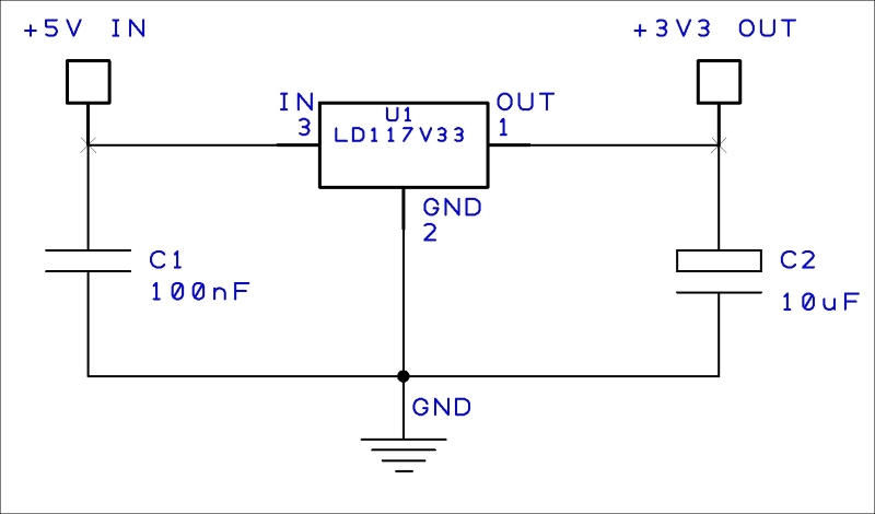
For our power supply, we're going to use a basic 3.3V voltage regulator (type LD1117V33) that will take our slightly more plentiful +5V supply from the Raspberry Pi and regulate it to a nice smooth +3.3V supply. We should be able to draw a few hundred milliamps from this supply—enough for the I/O circuitry on our security system.
The parts required for our power supply are as follows:
- A LD1117V33 voltage regulator
- A 100nF, 16V ceramic capacitor
- A 10uF, 16V electrolytic capacitor
Here's the circuit diagram for our +3.3V power supply:
As with all our components, the LD1117V33 regulator is widely available from many electronic component suppliers.
Our power supply can be easily built on a small piece of strip board like this:
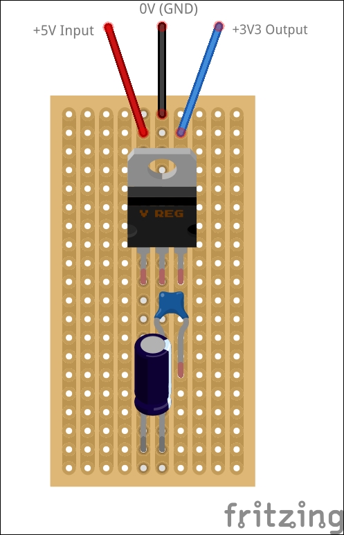
Note
The strip board is shown from the top in the preceding layout. That is, the copper tracks are on the underside of the board and the components are inserted from the plain top-side and soldered to the strips underneath. In this layout, it's not necessary to cut any of the tracks on the strip board.