
Now that we have built our port expander, we need to get it ready to connect our sensors to. First, we need to install the tools on the Raspberry Pi to allow us to use the I2C bus and program devices connected to it, including the MCP23017 chip that makes up our port expander.
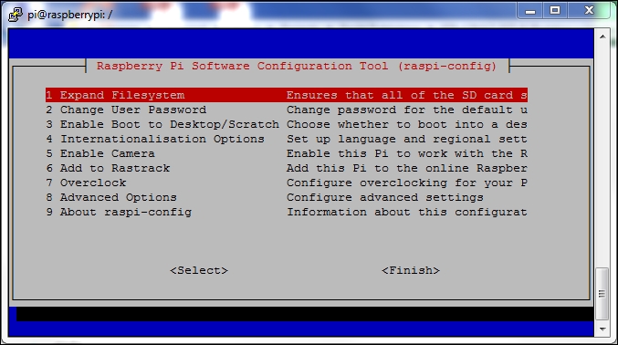
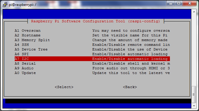
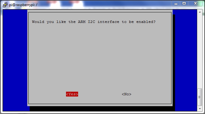
It's highly likely that the module for using the I2C bus hasn't been loaded by default. Fortunately, doing this is fairly straightforward and can be done using the Raspberry Pi configuration tool. Perform the following steps:
Now that the I2C bus has been enabled, we need to set up the operating system so that the required modules are loaded each time the system boots. To do this, perform the following steps:
So that we can easily access the I2C bus using Bash scripts, we need to install the i2c-tools package:
$ sudo apt-get install i2c-tools
Once installed, we should shutdown our system:
sudo shutdown –h now
After activity has stopped, switch off your Raspberry Pi, connect your port expander to the GPIO port, and power it back up so that we can start using it.
As a quick sanity check, you can see if I2C support has been loaded by typing:
$ ls /dev/i2c-*
This should give you a list of at least one bus—for example, /dev/i2c-1—if the module is loaded. If it's not, you'll probably get the following response:
ls: cannot access /dev/i2c-*: No such file or directory
In this case, you'll need to check back through the previous steps as something hasn't happened properly.
The i2c-tools package installs several different tools to help us use our port expander attached to the bus. The i2cdetect tool allows us to find I2C buses and devices attached to the busses.
To get a list of I2C busses on our system, type the following:
$ sudo i2cdetect -l
You should get the following response:
pi@raspberrypi ~ $ sudo i2cdetect -l
i2c-1 i2c 20804000.i2c I2C adapter
The preceding output shows that we have one I2C bus, and this will be the one connected to our GPIO. Note that earlier models of the Raspberry Pi may return the device ID as being i2c-0.
We can now use the tool to scan for all of the devices attached to our bus. We do this by specifying the bus ID, as in the following command:
$ sudo i2cdetect 1
With nothing attached to the I2C bus (that is, without our port expander attached) we'd expect to see the following output:
pi@raspberrypi ~ $ sudo i2cdetect 1
WARNING! This program can confuse your I2C bus, cause data loss and worse!
I will probe file /dev/i2c-1.
I will probe address range 0x03-0x77.
Continue? [Y/n] Y
     0  1  2  3  4  5  6  7  8  9  a  b  c  d  e  f
00:          -- -- -- -- -- -- -- -- -- -- -- -- --
10: -- -- -- -- -- -- -- -- -- -- -- -- -- -- -- --
20: -- -- -- -- -- -- -- -- -- -- -- -- -- -- -- --
30: -- -- -- -- -- -- -- -- -- -- -- -- -- -- -- --
40: -- -- -- -- -- -- -- -- -- -- -- -- -- -- -- --
50: -- -- -- -- -- -- -- -- -- -- -- -- -- -- -- --
60: -- -- -- -- -- -- -- -- -- -- -- -- -- -- -- --
70: -- -- -- -- -- -- -- --
pi@raspberrypi ~ $
Nothing found on the I2C bus
With our port expander attached, we should see the following output:
pi@raspberrypi ~ $ i2cdetect 1
WARNING! This program can confuse your I2C bus, cause data loss and worse!
I will probe file /dev/i2c-1.
I will probe address range 0x03-0x77.
Continue? [Y/n] Y
     0  1  2  3  4  5  6  7  8  9  a  b  c  d  e  f
00:          -- -- -- -- -- -- -- -- -- -- -- -- --
10: -- -- -- -- -- -- -- -- -- -- -- -- -- -- -- --
20: 20 -- -- -- -- -- -- -- -- -- -- -- -- -- -- --
30: -- -- -- -- -- -- -- -- -- -- -- -- -- -- -- --
40: -- -- -- -- -- -- -- -- -- -- -- -- -- -- -- --
50: -- -- -- -- -- -- -- -- -- -- -- -- -- -- -- --
60: -- -- -- -- -- -- -- -- -- -- -- -- -- -- -- --
70: -- -- -- -- -- -- -- --
pi@raspberrypi ~ $
Our I2C port expander slave device can be found at the address, 0x20 (32 decimal).
You'll recall that we can add up to 8 of these devices to the I2C bus by setting the A0-A2 pins to a unique address. If A0 is set to high, then the address of the device will be shown as 0x21 (33 decimal)—and up to 0x27 (39 decimal), if all pins are high.
As discussed in the previous chapter, we can have 2 x 8-bit busses on our port expander, with each pin being defined as an input or output. On the expander board we built, we called them I/O BUS A and I/O BUS B.
To configure the MCP23017 chip on the I2C bus, we can send it the appropriate commands using the i2cset tool we installed earlier.
On our home security system, we are going to assign all of the pins on BUS A as inputs for connecting our sensors to it. To do this, we use the following command:
$ sudo i2cset –y 1 0x20 0x00 0xFF
Note
What does this command mean?
- -y: This runs the command without user interaction.
- 1: This is the ID of the bus (for example,
i2c-1). - 0x20: This is the address of the chip.
- 0x00: This is the data register on the chip (in this case, the PORT A pin assignment).
- 0xFF: This is the Value loaded into the data register (in this case, all pins as inputs—binary %11111111).
You can check that the data register has been set correctly by reading it using the following:
$ sudo i2cget –y 1 0x20 0x00
This should return a value of 0xFF, which is the value we set earlier.