
Making our zone circuits use 12V instead of 3.3V is as simple as changing the power supply, and in fact all of sensors we used so far can handle 12V power passed through their switches.
However, if we were to present the 12V circuit to the inputs on our GPIO port on the Raspberry Pi or our port expander, we would expect to see some magic smoke and smell something burning. So, we need to add some circuitry that allows us to use 12V alarm circuits as well as protect our control board inputs.
An effective way to protect our zone inputs from 12V alarm inputs is to use a little low-cost device called an opto-isolator. As the name suggests, this isolates the alarm circuit from the digital inputs of the control board using light.
Inside an opto-isolator (also called an opto-coupler) is an infrared LED, which transmits light to a photo-transistor when a current is passed through it, thus switching it on. The circuits are electrically isolated as they are controlled only by light.
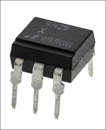
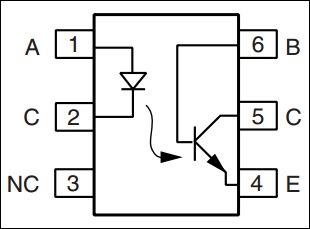
The 4N25 (shown in the preceding image) and 4N35 are low-cost, 6-pin opto-coupler devices, and most manufactures tend to use the pin layout shown in the following diagram:
Now that we know how we will couple our 12V alarm circuit with the inputs on our control panel, let's build the entire circuit, which we'll use for each of the zones that we add to our system.
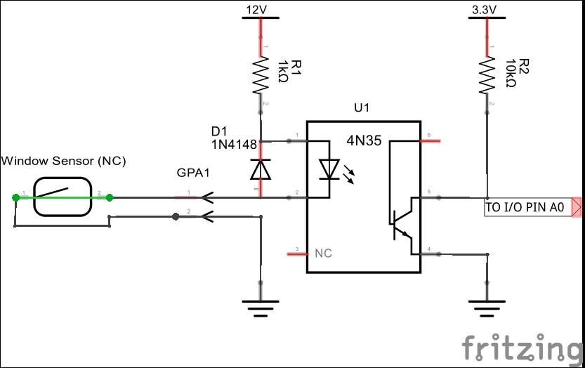
A 12V zone circuit optically isolated from the GPIO input
At this time, we're assuming that our zone circuits are normally closed—that is, the alarm triggers when the circuit is broken.
The 12V supply is passed through the LED of the opto-isolator with the current being limited by the 1-Kohm resistor. The 1N4148 diode, in reverse, is there to protect the opto-coupler from reverse-polarity voltages.
While the alarm circuit is closed, the current flows, and the LED is on. This keeps the transistor on and the input to the GPIO port is held low. If the alarm circuit is broken, the opto-coupler LED switches off, and this in turn switches off the transistor. The GPIO input is then pulled high by the 10-Kohm resistor.
This is quite simple but effective, eh?
The other advantage of this circuit is that it should fail positive—that is, if the opto-coupler should fail for any reason, the alarm input on the GPIO port should be pulled high, thus triggering it rather than it just failing silently.