
CONTENTS
12.2 Discussion of Cable Pulls
12.2.1 Maximum Allowable Tension on Conductors
12.2.2 Pulling Tension Calculations
12.2.3 Coefficient of Friction
12.2.4 Sidewall Bearing Pressure
12.2.5 Pulling Multiple Cables in a Duct or Conduit
12.2.5.1 Cradled Configuration
12.2.5.2 Triangular Configuration
12.2.5.3 Weight Correction Factor
12.3.1 Tension Out of a Horizontal Bend
12.3.2 Which Direction to Pull?
12.4 Cable Installation Research
Thomas A. Edison installed his earliest cables in New York City in 1882. The cables were placed in iron pipes in the factory and then were spliced together in the field every 20 feet in an egg-shaped splice casing. Other systems, such as by Brooks, Callender, and Crompton, were installed by 1885 where they also used short sections of iron conduit. American Bell Telephone Company installed the first flexible communication cables in 1882 and 1883 when cables were pulled into the conduit in the field. “Pumplogs” were first used for water supply lines, but were used in 1883 in Washington, DC, for telegraph cables. Tree logs were hollowed out, the exterior was trimmed to make them square, and the entire log was treated with creosote. These became the conduits of choice! So began the duct and manhole systems with the need to pull cables.
The Underground Systems Reference Book [1] of 1931 stated “It is necessary to inquire into the harmful effects of the pulling stress on the cable insulation. The conclusion that has been reached, based on tests and experience, is that satisfactory operation of the cable is assured, provided that it has suffered no mechanical injury.” It was recommended that a coefficient of friction between 0.40 and 0.75 should be used and that the total tension should be limited to 10,000 pounds. Little other advice was offered.
Significant advances were made in the understanding of cable pulling calculations with the 1949 paper by Buller [2] and the 1953 work of Rifenberg [3]. These papers provide the basic data for making cable pulls in all situations encountered in the field. They provide excellent quantitative data when used to calculate pulling tensions.
Even in the 1957 version of the Underground Systems Reference Book [4], there was little additional guidance given for such an important consideration as sidewall bearing pressure (SWBP) for distribution type cables. It was generally felt that 100 pounds per foot was acceptable. Later this was increased to 300 pounds per foot with no laboratory test work to support that value. Experience was still relied upon and 300 pounds met those criteria. Since the runs in city streets were relatively straight and manholes were located at every street intersection, these conservative values did not pose a problem.
Pipe-type cable systems pointed the way to the importance of accurate tension calculations. Here the avoidance of a splice could impact the cost of the system very significantly. Rifenburg’s work [3] included all the necessary options, but the allowable SWBP limits needed to be evaluated since the somewhat arbitrary value of 400 pounds had not actually been tested in a laboratory environment. The understanding of the need for such information led to the project for “Increasing Pipe Cable Section Lengths,” Electric Power Research Institute (EPRI) Final Report EL-2847, March 1983 [5].
A significant increase in the understanding of cable pulls was reached with the completion of EPRI Final Report, EL-3333, “Maximum Safe Pulling Lengths for Solid Dielectric Insulated Cables,” February 1984 [6]. A discussion of the results of these and other test work will be described in the following section.
12.2 DISCUSSION OF CABLE PULLS
Cable manufacturers have handbooks in print that describe methods for making safe cable pulls and for making the necessary calculations of pulling tensions. Computerized pull programs are available from suppliers of cable pulling compounds. Cable pull programs are available from EPRI [6]. There are many cable manufacturers, utilities, architect-engineering firms, and pulling equipment companies that also have programs.
An entirely new group of cable pulling compounds have become available since the EPRI project. They are able to achieve the very low coefficients of friction that their literature suggests—generally these lower values are for the higher SWBPs that are found in the field and in the newer test procedures.
12.2.1 MAXIMUM ALLOWABLE TENSION ON CONDUCTORS
The maximum allowable tension on cable conductors that should be used during pulls must be based on experience as well as good engineering. Factors that have an impact on the value include type of metal, temper, and factors of safety. The limits have been set based on only the central conductor of the cable or cables. This quickly establishes one of the safety factors because all of the components of a cable provide some mechanical strength.
One obvious limit is to consider the mechanical stress level at which the conductor will permanently deform/stretch. Upper limits have generally been set well below the elongation value of the conductor metal. The classic approach has been to use the values shown in Table 12.1, but the spread in values shown represent present-day data from suppliers. Even higher values have been recommended and published by the Association of Edison Illuminating Companies (AEIC) [7].
12.2.2 PULLING TENSION CALCULATIONS
The concept of the significant factors in a cable pull can be appreciated by looking at the equation for pulling a single cable in a straight, horizontal duct. The basic equation is:
(12.1) |
where
T = tension in pounds
W = weight of one foot of cable in pounds
L = length of pull in feet
f = coefficient of friction for the particular duct material and outer layer of the cable.
It is obvious that the weight of the cable and the length of the pull can be determined with great accuracy. The one thing that varies tremendously is the value of the coefficient of friction—it can vary from 0.05 to 1.0. In test conditions, values as high as 1.2 have been recorded! Even when the materials used in the duct and jacket are known, the type and amount of lubricant can be an important factor in this variation.
TABLE 12.1
Maximum Allowable pulling Tension on Conductors
Metal |
Temper |
Pounds per cmil |
Copper |
Soft (annealed) |
0.008 |
Aluminum |
Hard |
0.008 |
Aluminum |
3/4 Hard |
0.006 to 0.008 |
Aluminum |
1/2 Hard |
0.003 to 0.004 |
Aluminum |
Soft |
0.002 to 0.004 |
The significance of this is that the accuracy of the calculation cannot come out to six decimal places even if you have a calculator or computer with that many places! It is also not wise to argue whether one method of tension calculation can attain an accuracy of 1% better than another when one considers the probable inaccuracy of the coefficient of friction.
12.2.3 COEFFICIENT OF FRICTION
Since this is a significant variable in all calculations, let us look at this early in the discussion of cable pulling. What do we mean by “coefficient of friction?” Historically, the test apparatus for friction determination consisted of a section of duct that was cut longitudinally in half. The open duct was mounted on an inclined plane. A short sample of cable was placed near the top end and the angle of inclination was increased until the cable started to move as the result of gravity. Using the angle at which movement began, the static coefficient of friction was calculated. Generally, the angle of inclination could be decreased and the cable would maintain its slide. Using this second angle, the dynamic coefficient of friction was obtained.
As described above, many of the earlier publications suggested that the coefficient of friction that should be used varied from 0.40 to 1.0. This was, of course, very safe for most situations.
The EPRI project [6] demonstrated that there were other important issues that needed to be established in making accurate determinations of the coefficient of friction such as the level of SWBP. This force is duplicated in present-day test methods by applying a force that pushes the cable down on the conduit. The interesting fact is that this actually reduces the coefficient of friction in most instances! The quantity and type of lubricant are important. Too much lubricant can increase the friction. A more viscous lubricant should be used with heavier cables, etc.
12.2.4 SIDEWALL BEARING PRESSURE
When one or more cables are pulled around a bend or sheaves, the tension on the cable produces a force that tends to flatten the cable against the surface. This force is expressed in terms of the tension from the bend in pounds divided by the bend radius in feet.
(12.2) |
where
SWBP = force in pounds per foot
TO = tension from the bend in pounds
R = inner radius of the bend in feet
SWBP is not truly a unit of pressure, but rather a unit of force for a unit of length. In the case of a smooth set of sheaves or bend, the unit is the entire length of contact. However, any irregularity, such as a bump on the surface, or a small radius sheave with limited bearing surface (even though it may be part of a multisheave arrangement), reduces the effective bearing surface length. This must be taken into account in the calculation to prevent damage to the cable.
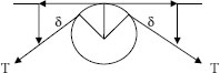
Figure 12.1 shows the mathematical derivation for a horizontal bend of one cable—ignoring the weight of the cable. As the angle approaches zero, the force between the cable and the bend approaches unity.
For multiple cables in a duct, the matter is complicated because of the fact that the SWBP is not equally divided among the cables. This situation is taken into account by using the weight correction factor which will be discussed later in this chapter.
FIGURE 12.1 Pulling forces in horizontal bend.
(12.3) |
where sin δ = δ for small angles and sidewall pressure,
(12.4) |
The T/R ratio is independent of the angular change of direction produced by the bend. It depends entirely on the tension from the bend and the bend radius with the effective bend radius taken as inner radius of the bend. Increasing the radius of the bend obviously decreases the SWBP.
SWBP limits that have been used historically are shown in Table 12.2. As with maximum pulling tension values, AEIC [7] has published limits that exceed the values shown in this table.
TABLE 12.2
Sidewall Bearing pressure Limits
Cable Type |
SWBP in pounds per Foot |
Instrumentation |
100 |
600 V nonshielded control |
300 |
600 V power |
500 |
5 to 15 kV shielded power |
500 |
25 to 46 kV power |
300 |
Interlocked armored |
300 |
Pipe-type |
1,000 |
12.2.5 PULLING MULTIPLE CABLES IN A DUCT OR CONDUIT
12.2.5.1 Cradled Configuration
A frequent requirement is to pull three cables into one duct. This brings the relative diameters of the cables into play with the inner diameter of the duct. If the cables are relatively small as compared with the duct diameter, the cables are said to be “cradled.”
The outer two cables push in on the center cable, making it to seem heavier than it actually is.
The pulling calculation handles this by using a “weight correction factor” that increases the apparent weight of that center cable.
The SWBP on the center cable in Figure 12.2 is influenced by the other two cables. The effective SWBP for the cradled configuration may be calculated from:
(12.5) |
See Equations 12.2 and 12.7 for definitions of the terms.
12.2.5.2 Triangular Configuration
When the diameter of each of the three cables is closer to one-third of the inner diameter of the duct, the situation is known as a “triangular” configuration.
In this situation, the top cable rides on the two lower cables without touching the duct wall.
The effect of this is that one cable effectively increases the weight of the two lower cables, but does not function as a longitudinal tension member. This means that one must use the cross-sectional area of only two of the cables in the maximum allowable tension determination in this example, not three cables.
The SWBP on the two lower cables in Figure 12.3 is influenced by the upper cable. The effective SWBP for the triangular configuration may be calculated from:
(12.6) |
The units are defined in Equations 12.2 and 12.7.

FIGURE 12.2 Cradled cables.
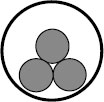
FIGURE 12.3 Triangular arrangement.
12.2.5.3 Weight Correction Factor
When two or more cables are installed in a duct or conduit, the sum of the forces developed between the cables and the conduit is greater than the sum of the cable weights.
Weight correction factor is therefore defined as:
(12.7) |
where
WC = weight correction factor (also merely “c”)
ΣF = force between cable and conduit, usually in pounds
ΣW = weight of the cable with the same units as above
For the typical case of three cables of equal diameter and weights in a conduit of given size, the weight correction factor is higher for the cradled configuration than the triangular configuration (Table 12.3).
The mechanism for this relationship is shown in Figure 12.4.
It is always safer to anticipate the cradled configuration unless the cables are triplexed or if the clearance is near the 0.5-inch minimum.
The equations for calculating the weight correction factor are:
Cradled:
(12.8) |
Triangular:
(12.9) |
where D = diameter of inside of conduit and d = diameter of each cable.
When the diameter of each of the three cables is about one-third of the inner diameter of the duct, a situation may occur where the cables may jam against the inside of the conduit. This generally occurs when the cables go around a bend or a series of bends. The “center” cable may try to pass between the outer two cables. When the sum of the diameters of the three cables is just slightly larger than the inner diameter of the duct, jamming can occur. Jamming increases the pulling tension manyfold and can result in damaging the cable or even pulling the cables in two, breaking pull irons in manholes, etc. (Figure 12.5).
TABLE 12.3
Weight Correction Factors
Configuration of Three Cables |
Weight Correction Factor |
Triangular |
1.222 |
Cradled |
1.441 |
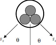
FIGURE 12.4 Weight correction.
The “jam ratio” of the cables in this duct needs to be evaluated. The equation for finding the jam ratio of three cables in a duct may be determined by:
(12.10) |
where Dd = inside diameter of the duct or conduit and Dc = outer diameter of each of the three cables.
The factor of 1.05 has been used to account for the probable ovality of the conduit in a bend and to account for the cable having a slightly different diameter at any point. If precise dimensions are known, this 5% factor can be reduced.

FIGURE 12.5 The condition that causes jamming for three cables in a conduit.
Where the jam ratio falls between 2.6 and 3.2, jamming is probable if there are bends in the run and unless other precautions are taken. To avoid any problems with jamming, it is wise to avoid pulls where the ratio is between 2.6 and 3.2.
How can jamming be avoided even though the calculation shows that the ratio indicates a significant probability of jamming? There are several solutions, some of which are obviously possible during the planning stages and some during the installation stage.
• Use a different size of cable or conduit to change the ratio.
• Have the cable triplexed (twisted together) at the factory.
• Tie the cables together in the field with straps.
• Use precautions at the feed point to keep a triangular configuration and allow no crossovers.
The National Electrical Code (NEC) ANSI C-1 requires that the total fill of a conduit be 40% or less for three cables in a conduit. This means that the cross-sectional area of all three of the cables cannot be more than 40% of the cross-sectional area of the conduit. Unfortunately, for 40% fill, the jam ratio is 2.74, which is in the lower danger ratio. An example of this situation is when three 1.095-inch diameter cables are installed in a conduit with an inner diameter of exactly 3.0 inches. (The actual inner diameter of a nominal 3-inch conduit is 3.068 inches!) If the designer tries to reduce the fill to say 38% to stay safely within the 40% limit, the jam ratio gets worse—2.81.
The NEC generally does not govern the utility practices; hence clearance limits are not based on percent fill. Utility practice considers that 0.5 inches of clearance is satisfactory for general pulls. Clearances as small as 0.25 inches have been successfully made when good engineering practices and careful field supervision are employed [7].
To complete this discussion of jam ratio, it is important to know that jamming can occur when more than three cables are installed in a conduit. A modification of the equation is necessary as shown:
(12.11) |
where
D = conduit inner diameter (ID)
n1, n2, n3 = number of cables of diameter 1, 2, 3, etc.
d1, d2, d3 = diameters of cables in groups 1, 2, 3, etc.
Theoretically any combination of cable diameters that fall in the critical zone can jam. Field experience has shown that the probability of jamming decreases as the number of cables increases.
Another consideration before cables are placed in a conduit is the amount of clearance between the cable or cables and the inside of the conduit. This may be quickly seen in the example of the three cables in a triangular configuration in Figure 12.1. The distance from the top cable to the inside “top” of the conduit is defined as the clearance.
The previous sections have presented some of the fundamentals of pulling cables. Now let us see how those factors, plus a few more, come together when we actually calculate the tension on a cable or cables that are to be installed.
12.3.1 TENSION OUT OF A HORIZONTAL BEND
Bends in cable runs are a fact of life. The important point is that the friction and SWBP around that bend increase the tension from the bend with respect to the tension on the cable into the bend.
(12.12) |
where
TO = tension from the bend
TIN = tension into the bend
c = weight correction factor
f = coefficient of friction
a = angular change of direction in radians
This is a simplified equation that ignores the weight of the cable. It is sufficiently accurate where the incoming tension at the bend is equal to or greater than 10 times the product of the cable weight per foot times the bend radius expressed in feet. The practical situation where TIN is less than 10 times the product of the weight and radius is where the cable is being fed at low tension into a large radius bend [8]. In such a case, the equation becomes:
(12.13) |
In order to fully appreciate the effect of the impact of the exponent of ecfa, Table 12.4 shows the multiplier of the tension for various values of the exponent. This also shows the significance of keeping the coefficient of friction down to a low value—especially when you have multiple bends in a run.
It is essential to remember that the exponent of e has three terms: weight correction factor, coefficient of friction, and angle of deflection. Sometimes this exponent is shown only as two factors because of limitations of older computer programs. In order to make that workable when multiple cables are installed, it is necessary to multiply the selected coefficient of friction by the weight correction factor. If you therefore have a situation where three cables will be cradled, for instance, the cfa value (from Table 12.4) is 1.442 times the coefficient of friction. Putting this another way, if you consider the proper coefficient of friction to be 0.2, and the cables will be in a cradled configuration, you must use a cfa value of 0.3. If there is only one cable, it means that you would use the 0.2 value of cfa for that same coefficient of friction since WC for one cable is unity.
TABLE 12.4
Multiplier of Tension Values for Various Exponents
cfa |
45°Bend |
90°Bend |
0.1 |
1.08 |
1.17 |
0.2 |
1.17 |
1.37 |
0.3 |
1.27 |
1.60 |
0.4 |
1.48 |
2.19 |
0.5 |
1.60 |
2.56 |
A large number of bends in a run can literally multiply the tension exponentially! This is one of the reasons that many installation practices keep the number of 90° bends to a maximum of three or four.
12.3.2 WHICH DIRECTION TO PULL?
There are always two possible directions that a cable can be pulled for any run—just as a cable always has two ends. Let us go through the calculations of an example that has one bend so that we can see how the pulling tension can vary (Figure 12.6).
Given: 1 × 1,000 kcmil copper cable
Weight of cable = 6 pounds per foot
Coefficient of friction = 0.5
Pulling from A to D:
Tension at A = 0
Tension at B = 300 × 6 × 0.5 = 900 pounds
ecfa = e1 × 0.5 × 1.5708 = 2.7130.7854 = 2.19
Tension at C = 900 × 2.19 = 1,971 pounds
Tension at D = −10 × 6 × 0.5 + 1,971 = 30 + 1,971 = 2,001
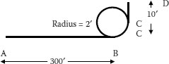
FIGURE 12.6 Pulling around a bend. Technical Conference, Portland, Oregon, June 1980.
This exceeds the long established 1,000-pound limit for a pulling grip, so this must be pulled with a pulling eye on the conductor. The established limit for a 1,000 kcmil copper conductor is based on the conductor kcmils multiplied by 0.008, or 8,000 pounds.
The maximum allowable tension from the bend at point C results in a SWBP of 1,971/2, or 985.5 pounds per foot, which is above the value generally agreed to by the manufacturers.
Pulling from D to A:
Tension at D = 0
Tension at C = 10 × 6 × 0.5 = 30 pounds
ecfa = e1 × 0.5 × 1.5708 = 2.7130.7854 = 2.19
Tension at B = 2.19 × 30 = 65.7 pounds
Tension at A = 300 × 6 × 0.5 + 65.7 = 965.7 pounds
This is satisfactory in all respects. The total tension does not exceed 1,000 pounds and the tension from the bend is well below accepted levels. A cable grip may be used to pull the cable from D to A.
From this example, it can be seen that it is always preferable to set up the reel as close to the bend as possible.
12.4 CABLE INSTALLATION RESEARCH
Pipe-type cable pulling was addressed by the EPRI in Final Report EL-2847, March 1983, entitled “Increasing Pipe Cable Section Lengths” [5]. SWBPs of up to 1,000 pounds per foot were recommended.
The fact that the suggested values for pulling tension and related considerations of extruded distribution cables had developed only from an understanding of past successful pulls made it seem reasonable to look at extruded dielectric cables using laboratory and field generated data. EPRI undertook Research Project 1519 in the late 1970s. The work was published as Final Report EL 3333 [6] in March 1983. Additional insight into pulling considerations was accomplished through the publication of AEIC CG5-2005 [7], “Underground Extruded Power Cable Pulling Guide”, in May 1990.
The values of SWBP, allowable maximum tension on the conductors, and maximum allowable tension on a pulling basket, are much less conservative than the level generally accepted by cable manufacturers.
Since there are obvious advantages for a utility to make longer pulls based on this data, a good deal of caution and experience is necessary.
Before reviewing the results, a few words of caution is needed. Field conditions are seldom ideal. The actual installation may not go as smoothly as was planned. For instance, when one believes that the cable may be pulled in one continuous motion, the actual pull may be made in a series of starts and stops. This alters the coefficient of friction because of the unplanned start, with the cable probably already far into the duct. When one anticipates excellent lubrication application, the amount of lubrication may be more or even less than that planned. Therefore,
• Do not blindly use these values to their upper limits.
• Be conservative.
• Follow the cable manufacturer’s recommendations.
The most dramatic findings of this EPRI research project over previously accepted values were:
• Pulling tension on both copper and aluminum conductors was about 50% greater than older limits.
• Allowable SWBP was as much as 200% greater than previously recommended.
• Coefficient of friction was about 50% lower—with values as low as 0.05.
• Basket grips could be used to pull 10 times (or more) the force previously recommended as long as tension limits on the conductor are not exceeded.
While the calculations have been found to be very accurate, field experience has shown that conditions may exist in the field that may greatly affect the success of the cable pull. A new installation can be calculated and results of the cable pull will follow the calculations fairly well. However, older conduits may have been exposed to unknown conditions. The following work practices and field conditions should be considered to make a successful installation without damaging the cable.
• Since buried conduit is not visible, verification of the location route should be made before setting up the cable pulling equipment. Conduit maps are helpful and a brief survey of the area to see if there has been new construction, which may affect the pull, is often required. Checking the areas where the pulling equipment and reels of cable are to be set up for the pull will often times save a lot of field modifications. Choosing these locations is especially important in a congested area or narrow streets or alleys.
• Older conduits may be damaged, contain stones and dirt, or have sections that have shifted leaving ridges. It is therefore recommended that the older conduits be inspected for these conditions. This can be done by pulling a mandrel through the conduit and inspecting its condition upon leaving the conduit pull.
• Measurements should be made while the cable is being installed so as to monitor any conditions that could cause possible damage. Equipment that contains a dynamometer to indicate pulling tensions is available. Some equipment contains charting facilities, which will record the pulling tensions as the pull progresses. These measurements are very important when installing transmission cable in a pipe.
• Feeding tubes are flexible metal tubes, which guide the cable toward the conduit or pipe. Their purpose is to supply smooth arc so that the cable is not damaged when entering a manhole. They are often used when installing transmission cable. This flexible metal tube must be sized to match the diameter of the conduit or pipe into which the cable is being installed.
• Lubricating compounds or fluids are used to reduce the coefficient of friction as previously mentioned. These come in a variety of viscosities and contain lubricants that must be compatible with the cable being installed. As an example paper-insulated lead covered (PILC) cable with a bare lead sheath was installed with a lubricant consisting of a hydrocarbon based grease. This lubricant, while reducing the pulling tension, also provided corrosion protection to the lead. Conduits that contain this grease may require cleaning before installing a cable with an outer coating with semiconducting properties. Otherwise, the semiconducting properties of the new cable will deteriorate with time. Prelubrication of the conduit will ensure a better distribution of the lubricating material and ultimately reduce the pulling tension for the installation.
• Attachments to the cable for pulling operations vary with the amount of tension expected and the type of cable being installed. A woven basket grip is very useful for short pulls of limited tension. These grips are very popular when pulling three single conductor cables. The basket grip fits around all three conductors and as tension is applied during installation, the basket fits more tightly against the three conductors. It is important that each cable of the bundle has a sealed end so that water cannot enter the strands during installation. This precaution is needed as some conduits contain standing water, and that water can be forced into the stranding of the conductor during the cable installation. PILC cable requires a lead seal to be installed over single-conductor and three-conductor cables. It is necessary for the conductors to be wiped into the pulling eye for strength.
• Installing cables in a high-rise building offers some unique situations. Foremost is the place that you are going to set up the pulling equipment as well as the reel of cable being installed. Choice can be made to install the reel of cable in the upper floors or to feed the cable in from the lower floors. Installation of vertical pulls must take into account the type of grips that will be used as well as intermittent grips if required. Methods of holding cable when intermittent grips are used require special attention in order to generate enough slack to get grips to hold their respective weight. Clamping devices used to support vertical cables must be designed so that they do not damage the cable while providing the function of holding the cable.
• Lines used to pull cable vary mostly by the amount of tension they may be subjected to during installation. Hemp and braided plastic ropes may be used on short pulls. Longer pulls, such as those on high-pressure fluid-filled pipe cable installations will require steel rope. Steel rope is also available with a plastic coating.
• Installation of a cable in a conduit, which already contains cable, is not recommended. Called a pull-by, it is very difficult to prevent damage to the existing cable or the cable being installed. Not only is it difficult to guard the cable against damage, it is also difficult to detect that damage incurred. Damage may occur to the jackets, sheaths, and neutral inside the conduit without detection.
1. Underground Systems Reference Book, 1931, NELA.
2. Buller, F. H., August 1949, “Pulling Tension During Cable Installation in Ducts or Pipes,” General Electric Review, Vol. 52 (No. 8), pp. 21–33, Schenectady, NY.
3. Rifenberg, R. C., December 1953, “Pipe-line Design for Pipe-type Feeders,” AIEE Transactions on Power Apparatus and Systems, Vol. 72, Part III.
4. Underground Systems Reference Book, EEI, 1957.
5. “Increasing Pipe Cable Section Lengths,” EPRI Final Report EL-2847, March 1983, EPRI, P. O. Box 10412, Palo Alto, CA 94303-0813.
6. “Maximum Safe Pulling Lengths for Solid Dielectric Insulated Cables,” EPRI Final Report EL-3333, February 1984, EPRI, P. O. Box 10412, Palo Alto, CA 94303-0813.
7. Underground Extruded Power Cable Pulling Guide, AEIC CG5-2005, Association of Edison Illuminating Companies, P. O. Box 2641, Birmingham, AL 35291-0992.
8. Kommers, T. A., June 1980, “Electric Cable Installation in Raceways,” Pulp and Paper Industry Technical Conference, Portland, OR.