
CONTENTS
23.3.1 Corrosion Under Direct Current (DC) Conditions
23.3.2 Corrosion Under AC Conditions
23.5 Mitigation of Armor Corrosion
Submarine cables generally have a metallic armor consisting of one or two layers wound around the outside of the cable. The main function of the armor is to provide mechanical strength during the installation and recovery of the cable since the conductor alone may not have sufficient tensile strength for this purpose.
The armor provides another function as the path for conduction of the return current. Single-conductor submarine cables are frequently spaced a considerable distance apart to preclude the chance of more than one cable being mechanically damaged as a result of a single incident. When the spacing is about 100 feet—about 30 meters—on centers (300 to 500 times the diameter of a single cable), the return current approaches the current in the central conductor. The effect of an increase in spacing above 100 feet (30 meters) is negligible.
Paths that may be available for this return current are:
• The metallic armor wires
• Specially designed return path under the armor
• A metallic sheath
• Reinforcing tapes used in pressurized cables
• Shielding tapes
• Sea and soil surrounding the cables
The choice of a three-conductor or single-conductor cables for large power cables is an important decision. For this moment, we will assume that single-conductor cables have been chosen. We will deal with that situation since it may be of critical importance in the cable design selection.
When the line length is more than 2 miles (3 kilometers), consideration must be given to connecting the components in the cable together. Frequently, a metallic sheath is protected by an insulating jacket to reduce the possibility of corrosion. To prevent electrical breakdown of the insulating jacket, electric connections are usually made at suitable intervals between the sheath, the armor, and the sea/soil. This may be done during the manufacturing process so that no visible signs of interconnection are available or they may be made externally.
This chapter will concentrate on the effects of alternating current (AC) corrosion as a result of return current flow in the “armor system”—the parallel paths formed by the metallic armor wires, any supplemental return conductor or reinforcing tapes, a metallic sheath, and/or a metallic shield. If all of the current stayed in the metallic path or paths, there would not be AC corrosion. The fact is that the current flows off the metal and into the sea or seabed and later returns. It is this process of current leaving and returning to the surface that results in the deterioration. Unfortunately, the metal that is removed by the current does not plate back as the current returns; the greater the current, the greater the damage. This is called AC corrosion (see Chapter 22).
The amount of current will now be considered for single-conductor cables on a system where the phase rotation is A, B, and C and the cables are arranged in a flat configuration as shown in Figure 23.1.
In the case of these three cables with a balanced load three-phase system, the vector sum of the three currents is zero. That is, the currents in each phase all have the same effective value and are 120 degrees out of phase with one another.
Hence,
(23.1) |
We are now going to make the very reasonable assumption that the armor system is connected to ground at more than one location. Even though two grounding points might be a few feet apart, the currents that will be described will flow between these points. The more realistic situation is that the armor system is grounded for the entire route and hence, these currents will flow everywhere in the armor system circuit.
A schematic of the system is shown in Figure 23.2. Only two of the possible components in the armor system are shown to keep the system somewhat simple.
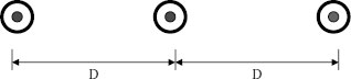
FIGURE 23.1 Single-conductor cables spaced apart.
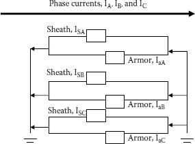
FIGURE 23.2 Parallel currents in spaced single conductor cables.
The shield loss for each phase of a multigrounded cable may be calculated from the following formulas:
A and C phases:
(23.2) |
B phase cable:
(23.3) |
where WLS = micro watts per foot.
Total loss:
(23.4) |
and
(23.5) |
(23.6) |
(23.7) |
(23.8) |
t = thickness of metal tapes or return conductor/sheath in inches
f = frequency in hertz
D = distance (spacing) between centers of cables in inches
rM = mean radius of shield in inches
I = conductor current in amperes
ρ = apparent resistivity of shield in ohms-circular mils per foot at operating temperature
Effective values in ohms-circular mils per foot:
Overlapped copper tape |
30 |
Overlapped bronze tape 90-100 |
47 |
Overlapped Monel tape |
2,500 |
Overlapped Cupro-nickel tape 80-20 |
350 |
Lead sheath |
150 |
Aluminum sheath |
20 |
Aluminum interlocked armor |
28 |
Galvanized steel armor wire |
102 |
5052 aluminum alloy |
30 |
Galvanized steel interlocked armor |
70 |
Stainless steel SS304 |
43 |
See the discussion of ampacity and of metallic shield losses for additional insight into the general problem in Chapter 14. The fact is that the conductor and shield arrangement in a multigrounded system is a one-to-one transformer so the greater the current in the phase conductor of most cable systems, the greater the current induced in the armor system—and hence the chances of corrosion escalate. This is a catch 22 situation in that the desire for additional armor strength and protection runs contrary to the need to reduce sheath currents and hence power losses.
Another way to consider this situation is that the more the metal in the armor system, the closer the current flow comes to the full phase current in the central conductor.
Three-conductor cables have negligible current in the armor system as long as the load is reasonably balanced. An unbalanced load does induce current in the armor system and may create some of the same concerns about armor corrosion as singleconductor cables. The same is true if the three single-conductor cables are tightly laid together—in the form of a triangle. This defeats the concept of spacing them apart to avoid the same ship or anchor breaking all of them at one time.
The point is that the corrosion of a three-conductor or three tightly spaced single-conductor submarine cables is considerably less of a factor than for the spaced single-conductor cables. An unbalanced load here may become significant.
Although the armor is occasionally insulated, this discussion will assume that the armor is bare and hence in contact with the sea for its entire length. Even in the situation of insulated armor wires, it is prudent to anticipate some damage to the insulating layer during installation or service-inflicted conditions. One single break in the insulating layer could be a very serious corrosion point unless other measures are taken.
The contact between the metallic armor and the sea, in the presence of an electric field, requires a thorough study of the corrosion factors that could be possible. Only a brief overview of the problems will be addressed here. Three types of metals are used for the armor wires of submarine cables:
• Galvanized steel
• Copper
• Aluminum alloys
• All of the above with coverings for each wire
23.3.1 CORROSION UNDER DIRECT CURRENT (DC) CONDITIONS
The corrosion properties of metals in seawater are frequently analyzed in the laboratory by performing weight loss studies. An example of such a test is shown in Table 23.1.
The test setup consisted of samples of cold drawn wire having diameters of 4 to 6 mm. DC was circulated between two parallel lengths of the same material about 100 mm long and maintained at a separation of 80 mm in a solution of 3.5% NaCl.
Aluminum, aluminum alloys, and steel corrode according to their electrochemical equivalent and to the transfer of electric charge when subjected to DC in anodic circumstances. Weight loss on anodic copper was diminished due to the formation of a Cu2O layer that stopped the current flow with these test conditions. Very low weight loss was observed in cathodic conditions.
TABLE 23.1
Weight Loss Under DC and 1,000 Amperes/meter2 for 30 Minutes
Metal |
Weight Loss for Anode, in kg/m2 |
Weight Loss for Cathode, in kg/m2 |
Aluminum alloy |
0.21 |
0.004 |
Copper |
0.14 |
0.0012 |
Galvanized steel |
0.65 |
0.0008 |
TABLE 23.2
Weight Loss Under DC and 1,000 Amperes/meter2 for 1,000 Hours
Metal |
Weight Loss for 10 A/m2, kg/m2 |
Weight Loss for 100 A/m2, in kg/m2 |
Weight Loss for 1,000 A/m2, in kg/m2 |
Weight Loss for 7,000 A/m2, in kg/m2 |
Aluminum Alloy |
3.5 × 10⁻² |
6.0 × 10 |
2.0 × 10³ |
11.0 × 10³ |
Copper |
2.5 × 10⁻² |
7.0 × 10⁻¹ |
1.5 × 10² |
0.4 × 10³ |
Galvanized Steel |
1.5 × 10⁻¹ |
1.2 × 1 |
0.7 × 10 |
1.5 × 10² |
23.3.2 CORROSION UNDER AC CONDITIONS
Weight loss tests for the same materials were performed under AC conditions for different current densities but for the same 1,000 hour time and in accordance with ASTM G1-72.
There is a well-defined threshold of AC density for these materials. Below this threshold, weight loss is not dependent on current density and follows the rules for chemical weight loss—hence, they are dependent on their electrochemical potentials.
Examination was made of this same aluminum alloy armor from a submarine cable with 5 years of service. Almost all of the corrosion was due to chemical corrosion since there was negligible AC current in the cable and the weight loss of 0.054 × 10⁻³ kg/m2 compared closely with the data from Table 23.2.
Copper and galvanized steel show a uniform pattern of corrosion in an AC environment while aluminum alloys demonstrate pitting and localized corrosion. An example of steel wire corrosion after 10 years of service is shown in Figure 23.3.
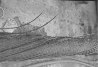
FIGURE 23.3 Steel armor wires corroded by AC current.
23.5 MITIGATION OF ARMOR CORROSION
EPRI Project EL-4042 demonstrated that 1 mA of current made AC corrosion a serious problem for copper concentric neutrals on underground residential distribution (URD) cables. There is no sufficient test data to clarify the amount of AC current in the armor wires of submarine cables to cause rapid deterioration, but field experience with single-conductor cables in a salt water environment has shown that in 10 years corrosion has seriously damaged the cable.
The reverse side of this experience has shown that such single-conductor cables that have a designed return circuit under the armor with a conductivity equal to that of the central conductor have had a new appearance after 12 years of service.
1. Corrosion of the Concentric Neutrals of Buried URD Cables. EPRI EL-4042, Project 1144-1, Final Report May 1985.