
Chapter 2. Introduction to the Tribology of Plastics and Elastomers
The first chapter of this book was an introduction to fatigue. This chapter is a brief introduction to tribology. There are many texts that deal with this subject in much more detail.1. and 2. Tribology is the science and technology of surfaces in contact with each other and therefore covers friction, lubrication, and wear. Tribological properties are most often of concern when the materials are used in bearing applications. Especially when engineering plastics are used for bearing materials, they must have a suitable combination of mechanical and tribological properties under the conditions experienced in use. The three main performance areas that need to be examined for bearing are friction, wear, and limiting PV. However, tribological properties often need to be considered in other applications.
2.1. Friction
Frictional force is not always intuitive. This is apparent when one considers two blocks on a plate as shown in Figure 2.1.
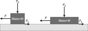
The blocks are of equal mass and surface finish. The block on the right has twice the surface contact area of the other. An equal vertical force (Fn) is applied to each block. Both blocks are made to slide by the application of an equal horizontal force (F). A frictional force (Fs) resists the sliding motion. What most people will find surprising is that the frictional force (Fs) will be the same for both blocks even though the surface contact area is different. The frictional force (Fs) depends only on the vertical applied force (Fn) and is described by Equation 2.1.
(2.1)
The coefficient of friction is a parameter that depends on the combination of block and plate materials. It is approximately 0.5 for many material combinations, but fortunately not for all materials. As it turns out, the coefficient of friction is constant only under a given set of conditions. It can vary with velocity and temperature. There are actually two coefficients of friction for each material pair. The static coefficient of friction (μs) is determined from the force that is just enough to start the block moving. Once the block is moving, the dynamic coefficient of friction (μd) is determined from the force that is just enough to keep the block moving. Dynamic coefficient of friction is sometimes called kinetic coefficient of friction.
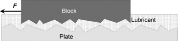
The sliding surfaces do not contact completely over the expected contact area. Even the smoothest surface is “rough” at a microscopic scale as shown in Figure 2.2. At the junction between the two surfaces, the materials only touch over small patches, called “asperities.” The asperities support the load and deform (especially for plastics, elastically or plastically) to reach an equilibrium. When the apparent contact area is measured or calculated, it is not the real contact area in tribological terms. The apparent contact area is much larger than the true contact area.
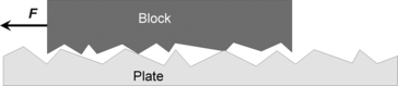
When movement of the block occurs, the asperities rub against one another creating a natural resistance to movement as they slide over and deform one another. This resistance to the movement is the frictional force (Fs) as defined by Equation 2.1.
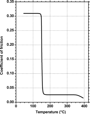
Frictional properties of plastics differ markedly from those of metals. The coefficients of friction vary with applied load, velocity, and temperature. Figure 2.3 shows an example of the temperature dependence of the coefficient of friction for a polyimide, Vespel® SP-21.
 |
| Figure 2.3 |
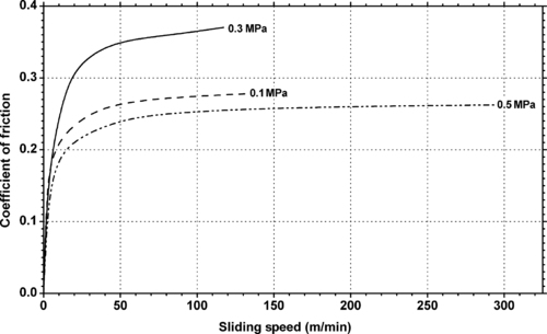
The rigidity of even the highly reinforced resins is low compared to that of metals; therefore, plastics do not exactly behave according to the classic laws of friction. Metal to plastic friction is characterized by adhesion and deformation of the plastic, resulting in frictional forces that are more dependent on velocity rather than load. In thermoplastics, friction generally decreases as load increases. Figure 2.4 shows the dependence of the coefficient of friction of Teflon® PTFE as a function of both velocity (sliding speed) and load (pressure).
 |
| Figure 2.4 |
A unique characteristic of most thermoplastics is that the static coefficient of friction is typically less than the dynamic coefficient of friction. This accounts for the slip/stick sliding motion associated with many plastics on metal and with plastics on plastics.
2.2. Lubrication
Lubrication is the common approach to reducing friction. The lubricant resides between the two surfaces as shown in Figure 2.5. When an incompressible solid or liquid lubricant is inserted between the two contacting surfaces, it tends to fill the gaps between the asperities (as shown in Figure 2.5). It acts as a fluid bearing surface and allows smoother movement of the two materials. This gives a greatly reduced frictional force than for unlubricated movement. Traditional fluid lubricants are oils, but it is also possible to use solid lubricants such as graphite, molybdenum disulphide (MoS2), or PTFE. The solid lubricants are often dispersed in oil or water.
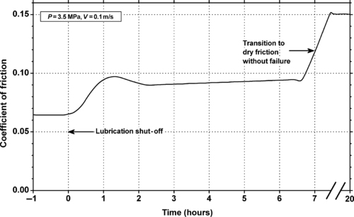
Lubrication is classified as partial when there is still some contact between the block and the plate. The coefficient of friction for partial lubrication is generally between 0.01 and 0.1. When there is a total separation of the block and the plate by a layer of lubricant it is called fully hydrodynamic. The coefficient of friction for fully hydrodynamic lubrication is usually between 0.001 and 0.01. Lubrication is common and effective even for materials with a very low coefficient of friction, such as Teflon® PTFE because the lubricant layer not only greatly reduces the coefficient of friction but also reduces the surface damage caused by the asperities rubbing together. Figure 2.6 shows the effect of lubrication on Vespel® SP-21, which is a polyimide plastic that contains 15% graphite for internal lubrication. This figure plots the coefficient of friction versus time of the Vespel® SP-21 rubbing against AISI 1080 carbon steel. The system is lubricated with oil at the start, but then the flow of oil between the two surfaces is shut off after 1 hour. As can be seen, the coefficient of friction starts to rise and continues to do so slowly. When the lubricant is completely gone, the coefficient of friction rises to the level characteristic of this internally lubricated material.
2.3. Wear and Erosion
Wear is defined as the removal of material from a solid surface as a result of friction or impact. Considering the frictional block and plate model in Figure 3.1, it is easy to imagine that the constant movement of the asperities over one another will lead to material removal as the asperities are ground down. Wear occurs and material is lost from both surfaces, even if one is much harder than the other.
2.3.1. Classification of Wear
One may envision many contact scenarios that lead to wear. Wear has been classified in various ways. One possible classification is based on the fundamental motion that is causing the removal of the material. Many schemes based on motion have been proposed, but none is universally accepted. As an example, one particular scheme has been proposed by Blau. 3 This scheme, shown in Figure 2.7, puts wear processes into one of three categories based on the type of motion producing the wear. The details of each of these processes may be found in the original reference. However, processes that only displace material and not remove it such as galling, scuffing, and scoring are not considered wear, but are considered surface damage. When applying this scheme to real-world wear, problems can get complicated because often more than one process may be the cause of the wear observed.
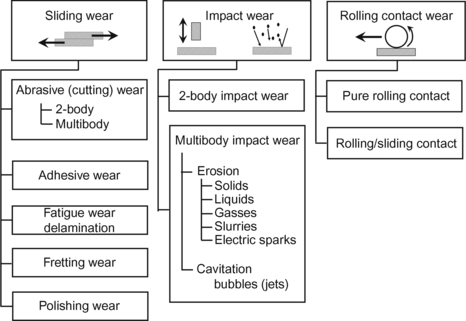 |
| Figure 2.7 Major categories of wear classified by the type of relative motion encountered. 3 |
Budinski4 classifies wear processes into four categories based on mechanism, i.e., abrasion, erosion, adhesion, and surface fatigue as shown in Figure 2.8. The reference has the details of these mechanisms.
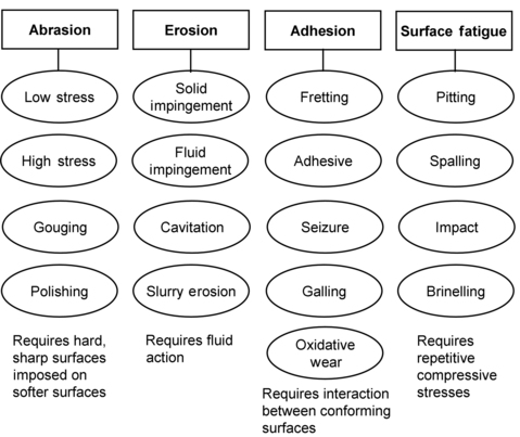 |
| Figure 2.8 Major categories of wear classified by mechanism. 4 |
A distinction between erosion and abrasion should be noted. This is because testing is quite different. Solid particle impingement (erosion) refers to the striking and rebounding of solid particles from the surface. The particles transfer energy to the surface during that strike and rebound. That depends upon the particle velocity, angle of strike, and particle mass. Fluid impingement and cavitation are usually classified as erosion but the process is different.
The most common wear mechanism for thermoplastics is adhesive wear. Adhesive wear occurs when opposing/mating surfaces slide against each other, and fragments of one surface pull off and adhere to the other. The adhesive forces between the polymer and the counterpart are sufficient to inhibit sliding at the original interface. The harder of the opposing surfaces scrapes or abrades away the mating part. The adhesive junctions which form at the real points of contact rupture within the polymer itself and a layer of polymer is deposited on the counterpart. The counterpart surface can become effectively smoother leading to a reduction in the rate of wear. PTFE has been shown to be very effective at forming such a transfer film. 5 The tribological properties of most neat polymers (without additives) are relatively poor since adhesion of most polymeric transfer layers to metal counterparts is very weak.
2.3.2. Characterizing Wear
Even though there are many wear mechanisms or processes, wear is usually characterized by several parameters. These will be discussed in the following sections.
2.3.2.1. Wear Rate
Wear can be characterized in several ways. It is often reported as the removal of material on a volume, weight, or depth (thickness) basis. The rate of wear would also relate the amount of material removed to a variable such as time, cycles, or distance. Tests for making these measurements in the laboratory are discussed in the next section.
2.3.2.2. Wear Factor
The wear resistance of materials can be predicted from an experimentally determined wear factor. The wear factor is derived from an equation relating the volume of material removed by wear in a given time per unit of load and surface velocity. The general equation is given in Equation 2.2 and the special case of a flat surface is given in Equation 2.3.
(2.2)
For flat surfaces:
(2.3)
The time, velocity, pressure, and depth units are often different so the wear factor units need to be carefully matched.
Once a K wear factor is established, it can be used to calculate wear rates of such components as bearings and gears. However, the engineer must bear in mind that the wear rate of the plastic is affected by test PV, plastic material finish, part geometry, ambient temperature, mating surface finish, mating surface hardness, and mating surface thermal conductivity. But at a given PV condition, a lower wear rate factor also indicates lower wear rate. Nonetheless, as a relative measure of one material versus another under the same operating conditions, K factors have proved to be highly reliable.
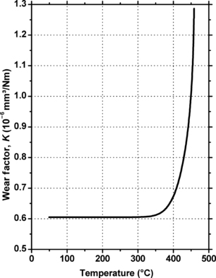
The wear factor is temperature dependent. One example of this is shown in Figure 2.9 for a particularly thermally stable material, Vespel®.
 |
| Figure 2.9 |
Materials can rise in temperature during use even though the general environment is not a high-temperature one. The PV multiplier also represents the work done per unit area per unit time at the contact surface. A part of this work may then be transformed into heat. The amount of heat generated proportional to the PV value times the coefficient of friction, μ, as shown in Equation 2.4.
(2.4)
The actual temperature rise will also depend on the thermal conductivity and heat capacity of the materials. If the thermoplastic is sensitive to temperature change (typified by low heat deflection temperature or low melting point), this frictional heating may cause the polymer to soften or even melt. This means the wear mode (thus the wear rate) and part shape are changed rapidly, and the wear part can no longer function adequately due to large dimensional deformation. High friction coefficient is often indicative of such a softening of the thermoplastic part.
The temperature at which wear increases dramatically is called the wear transition temperature. This is sometimes reported in vacuum or inert atmosphere and in air. For instance, the Vespel® products used in several of the preceding charts have a wear transition temperature in the range of 482–538°C in vacuum or inert gases, and 371–399°C in air. Figure 2.9 shows the wear factor of Vespel® bearings is essentially constant over a wide range of temperature but then it rises quite rapidly and from the chart one would say the wear transition temperature is someplace between 350°C and 400°C.
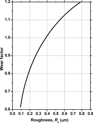
Mating materials can have different degrees of smoothness, or conversely roughness. There are devices that characterize roughness, where higher roughness values mean the surface is rougher. The effect of the roughness on the mating surface on the wear factor of Vespel® SP-21 is shown in Figure 2.10.
 |
| Figure 2.10 |
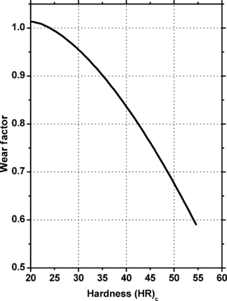
The hardness of the mating material can also affect the wear factor. This is shown in Figure 2.11 for Vespel® SP-21.
2.3.2.3. PV Limit
In addition to the wear factor and coefficient of friction, another key parameter that is often used to select a material for parts requiring excellent resistance to the effects of wear is the PV limit. PV is the product of load or pressure (P) and sliding velocity (V). By definition, the PV limit is simply a PV multiplier above which the material can no longer function as a wear part due to softening, melting, and deformation. But in reality, the PV limit remains more a concept than a clear-cut number that one can determine experimentally.
In a bearing application, the PV limit for a material is the product of limiting bearing pressure MPa (psi) and peripheral velocity m/min (fpm), or bearing pressure and limiting velocity, in a given dynamic system. It describes a critical, easily recognizable change in the bearing performance of the material in the given system. When the PV limit is exceeded, one of the following manifestations may occur:
1. Melting
2. Cold flow or creep
3. Unstable friction
4. Transition from mild to severe wear
PV limit is generally related to rubbing surface temperature limit. As such, PV limit decreases with increasing ambient temperature. The PV limits determined on any given tester geometry and ambient temperature can rank materials, but translation of test PV limits to other geometries is difficult.
As long as the mechanical strength of the material is not exceeded, the temperature of the surface is generally the most important factor in determining PV limit. Therefore, anything that affects surface temperature will also affect the PV limit of the material. The following factors are known to affect the PV limit:
1. Coefficient of friction
2. Thermal conductivity of both mating materials
3. Lubrication
4. Ambient temperature
5. Running clearance
6. Hardness
7. Surface finish of mating materials
2.4. Tribology Testing
There are perhaps a hundred designs of machines called tribometers that may be used to measure wear and coefficient of friction. 6 There are so many designs because one tried to simulate the expected endues environment and conditions as close as possible. Only a few of these tests and machines will be discussed here. These will be the most common ones.
2.4.1. Testing for Friction
Most tribometers used to study wear will also measure coefficient of friction. But there are a few tests aimed just at coefficient of friction tests. As mentioned in Section 2.1, there are two coefficients of friction that can be measured. The static coefficient of friction (μs) is found from the force that is just enough to start the block moving. Once the block is moving, it is possible to measure the dynamic coefficient of friction (μd) from the force that is just enough to keep the block moving.
One simple way to measure the static coefficient of friction is to place a block of steel on a plaque of test material. The plaque is lifted on one end creating an inclined plane that is tilted higher and higher until the block starts to move as shown in Figure 2.12. The angle of tilt can be used to resolve the forces to calculate the static coefficient of friction as defined in Equation 2.5.
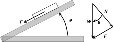
(2.5)
For plastic film and sheeting, the most common test is ASTM D1894-08 Standard Test Method for Static and Kinetic Coefficients of Friction of Plastic Film and Sheeting that is capable of measuring both the static and dynamic coefficients of friction (Figure 2.13).
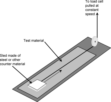 |
| Figure 2.13 |
Laboratory testing for friction and wear is often carried out using a motorized tribometer and there are various standardized and nonstandardized test methods available.
Friction in actual applications is very difficult to predict because there are:
1. a wide range of surface combinations
2. a wide range of lubrication methods and materials
3. the nonlinear relationship between the contact pressure, speed, and the coefficient of friction
4. the effect of temperature rise due to frictional heating
2.4.2. Wear and Abrasion Tests
2.4.2.1. Thrust Washer Abrasion Testing
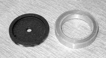
One of the most common abrasion tests is called the Thrust Washer Abrasion Test and is described by ASTM standard, D3702-94(2004) Standard Test Method for Wear Rate and Coefficient of Friction of Materials in Self-Lubricated Rubbing Contact Using a Thrust Washer Testing Machine. The machine can provide a large amount of quality and detailed information about wear of materials. Two of the manufacturers of the machine are the Falex Corporation and Plint Tribology Products.
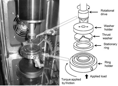
The machine tests a precision-machined washer shown in Figure 2.14. The opposing surface is a ring. The test plastic is usually a ring and the thrust washer is usually a steel mating material. In these tests, the stationary ring is mounted in an antifriction bearing equipped with a torque transducer. The moving specimen (thrust washer), which is mounted in the upper sample holder, presses against the stationary specimen.
The test specimens are loaded into the test machine as shown in Figure 2.15.
There are a number of selectable variables for this test:
1. The load pressing the washer and ring together (kg/cm2)
2. The speed or RPM from which the velocity can be calculated (m/min)
3. The ring holder temperature (or the environmental chamber)
4. The presence and temperature of lubricant if chosen
5. The time or number of rotations the experiment runs
The machine monitors the torque applied to the ring by friction. The machine can be set to run a specific number of revolutions or for a specific time. There is usually a break-in period in which the measured torque varies wildly so the experiment must be run until the measured torque stabilizes.
The tests, to be considered valid, are run until an equilibrium condition is reached. After the experiment, the wear depth and weight loss can be measured.
From this data, an array of wear rate and wear factor can be calculated as described in Section 2.3.2. The thrust washer test generates wear information for a material based on area contact, not line or point contact as needed in some bearing applications.
The thrust washer test is capable of generating wear data for plastic against metal, plastic against plastic, or against virtually any mating surface. Testing can be done for a wide temperature range and/or submerged in various fluids.
2.4.2.2. Pin-on-Disk Abrasion Testing
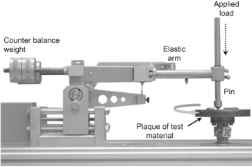
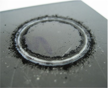
The Pin-on-Disk Tribometer, shown in Figure 2.16, consists of a flat, pin or sphere which is attached to a stiff elastic arm that is weighted down onto a test sample with a precisely known weight. The sample is rotated at a selected speed. The elastic arm ensures a nearly fixed contact point and a stable position in the friction track formed by the pin on the sample. The kinetic friction coefficient is determined during the test by measuring the deflection of the elastic arm, or by direct measurement of the change in torque by a sensor located at the pivot point of the arm. Wear rates for the pin and the disk are calculated from the volume or weight of material removed during the test. Figure 2.17 shows the track and wear debris on a test plaque. With this machine, one can control test parameters such as speed, contact pressure (hence PV), and time. With the right environmental chamber, one can also control and measure the effect of humidity, temperature, and atmospheric composition. The pin-on-disk measurement is usually done per ASTM G99-05 Standard Test Method for Wear Testing with a pin-on-disk apparatus.
2.4.2.3. Linear Reciprocating Abrasion Testing
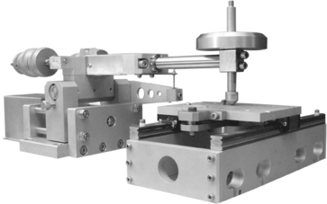
The pin-on-disk tribometer can be modified by replacing the rotating disk motor with a one directional reciprocating table as shown in Figure 2.18. This arrangement reproduces the reciprocating motion typical in many real-world mechanisms. The configuration of the mating surface to the test plaque on the reciprocating table can be point, line, or surface contact. The sample is moved at a controlled speed. The elastic arm ensures a nearly fixed contact point and a stable position in the friction track formed on the sample. The static friction coefficient is determined during the test by measuring the deflection of the elastic arm during each change in direction. Wear rates are calculated from the volume or weight of material removed during the test. The reciprocating abrasion measurement is usually done per ASTM G133-05e1 Standard Test Method for Linearly Reciprocating Ball-on-Flat Sliding Wear.
2.4.2.4. Taber Abraser
The Taber Abraser has been used to characterize wear for a long time. It is a standard ASTM test, ASTM D1044-08 Standard Test Method for Resistance of Transparent Plastics to Surface Abrasion. This historically has been an industry favorite, because it is inexpensive and easy to do. A test panel has a hole in the center. It is mounted in the Taber Abraser that is shown in Figure 2.19.
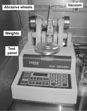
Weight is selected and added, as are the types of abrasive wheels. The wheel and weight assembly is lowered onto the test panels, which then rotates allowing the panel to be abraded by the wheels. A vacuum removes abraded debris. The panels are rotated for a given number of cycles, typically one thousand. By measuring the depth of the worn area or by weighing before and after test and knowing the number of cycles, the wear rate can be calculated in terms of thickness loss or weight loss per 1000 cycles. This measurement may also be converted to volume loss per 1000 cycles by geometric calculation using the measured density of the test material.
There are a couple of problems with this test. First, as the plastic is abraded, it tends to fill in the porosity of the abrading wheels. This makes them less efficient at abrading. The abrading wheels need to be cleaned or redressed every 100–200 cycles. This is especially true for materials containing perfluoropolymers. Secondly, the test has poor reproducibility. Comparisons of materials should be restricted to testing in only one laboratory. Inter laboratory comparison should use rankings of coatings in place of numerical values. The substrate disk must be very flat.
2.4.3. Erosion Tests
Erosion tests are usually based on dry material or slurries. They generally use gravity or pressure to force particles against the test plaque.
2.4.3.1. Falling Abrasive/Erosion Test
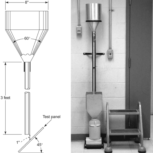
A simple, inexpensive reproducible abrasion/erosion test is the falling abrasive test described in ASTM D968-93(2001) Standard Test Methods for Abrasion Resistance of Organic Coatings by Falling Abrasive. Known weights or volume of sand, gravel, aluminum oxide, or silicon carbide are poured on a panel from a given height through a funnel and tube as shown in Figure 2.20. The panel is positioned at a 45° angle. The abrasive is collected for reuse. Abrasive such as aluminum oxide can be reused many times. When desired, after many tests, the fines can be removed by sieving. The change in weight per unit weight of abrasive is used to report abrasion/erosion rates.
2.4.3.2. Slurry Erosion Tests
There are a number of slurry erosion test machines discussed in the literature.7. and 8. Many of these pump slurry at high velocity at the surface of a test plaque. A simpler test is described in ASTM G75-07 Standard Test Method for Determination of Slurry Abrasivity (Miller Number) and Slurry Abrasion Response of Materials (SAR Number). The relative effect of slurry abrasivity is determined by measuring the mass loss of a block plastic elastomer after it has been driven in a reciprocating motion in a trough containing the slurry. A direct load is applied to the test plaque. The interior of the trough has a flat-bottomed or truncated “V” shape trough that forces the slurry particles to the reciprocating path taken by test specimen. The slurry may be of any material of interest such as sand in water or other liquid. The Miller Number Machine lifts slightly the test block and delays momentarily at the end of each stroke to allow time for fresh slurry material to flow back into the wear path. The test consists of measuring the mass loss of a part per unit time.
2.4.4. Standard Tests
Table 2.1 lists many, but not all, of the testing standards issued by ASTM and ISO.
2.5. Wear-Resistant Additives
Even among plastic materials with excellent natural lubricity, wear characteristics between two thermoplastics differ greatly. When an application calls for plastic on plastic, dissimilar polymers should be used and incorporated with one or more wear-resistant additives. Reinforcements such as glass, carbon, and aramid fibers enhance wear resistance by increasing the thermal conductivity and creep resistance, thus improving the LPV and working PV of the part.
PTFE has the lowest coefficient of friction of any internal lubricant. Its particles shear during operation to form a lubricous film on the part surface. Often referred to as the best lubricant for metal mating surfaces, PTFE modifies the mating surface after an initial break-in period. PTFE goes an extra step in lessening wear and fatigue failure by actually cushioning shock. What is most important about PTFE is its distribution throughout the thermoplastic compound. PTFE has a typical optimum loading of 15% in amorphous thermoplastic resins and 20% in crystalline resins. However, there is a price performance limit at which PTFE can actually begin to demonstrate diminishing returns.
MoS2, otherwise known as moly, is a solid lubricant usually used in nylon and other composites to reduce wear rates and increase PV limits. Acting as a nucleating agent, MoS2 creates a better wearing surface by changing the structure of nylons to become more crystalline, creating a harder and more wear-resistant surface. MoS2 will not lower the coefficients of friction like other modifiers, and its use is therefore confined to nylons where it has this crystallizing effect on the nylon molecular structure.
MoS2 also has a high affinity for metal. Once attracted to the metal, it fills the metal’s microscopic pores, making the metal surface slippery. This makes MoS2 the ideal lubricant for applications in which nylon wears against metal, such as industrial bushings, cam components, and ball joints. Two added benefits occur during molding: fast injection molding times which lower per part costs; and less and more uniform shrinkage.
Graphite’s unique chemical lattice structure allows its molecules to slide easily over one another with little friction. This is especially true in an aqueous environment and makes graphite powder an ideal lubricant for many underwater applications such as water meter housings, impellers, and valve seals.
Silicone or polysiloxane fluid is a migratory lubricant. A particular silicone fluid is chosen that is compatible enough with the base resin to allow compounding, yet incompatible enough to migrate to the surface of the compound to continuously regenerate the wear surface.
Perfluoropolyether (PFPE) synthetic oil marketed by DuPont under the trademark Fluoroguard® is an internal lubricant that imparts improved wear and low friction properties like silicone or polysiloxane fluids.
Silicone resin offers engineers several unique advantages based on its ability to be both a boundary lubricant and an alloying partner with the base resin. Silicone acts as a boundary lubricant because silicone moves or migrates to the surface of a part over time, by both diffusion as a result of random molecular movement, and by its exclusion from the resin matrix which is a result of migration. As a partial alloying material with the base resin, silicone remains in the component over its service lifetime, but because silicone is incompatible enough, the silicone is constantly moving from the matrix to the surface. This continuous secretion eases friction and wear at start-up and when high-speed lubricity is necessary. Silicone is excellent for start-up, high-speed, and low-pressure wear applications such as keyboard keycap receptacles and high-speed printer components.
Silicone fluid is available in a wide range of viscosities. The lower the viscosity, the more fluid the additive is, and the quicker it will migrate to the surface and provide lubrication. This is particularly important in wear applications that require numerous start and stop actions. However, if the additive’s viscosity is too low, the silicone can vaporize during processing, or migrate too quickly from the molded part.
Silicone and PTFE will work together to create a high-temperature grease which will create better wearing characteristics and lower friction, particularly at high speeds and during start-ups. When used together, PTFE acts as a thickening agent as well as an extreme pressure additive to make the grease at the surface. Because the silicone is constantly moving to the surface, this provides the added lubricity necessary during start-ups and at high speeds. Since failure at high speeds is more dependent on wear than failure at low speeds, and because the benefits of the silicone/PTFE synergy are most evident at these higher speeds, this combination should not be considered for low-speed components. In these cases, usually a PTFE-only compound is needed.
Glass fibers are mainly added to resins to improve both short-term mechanical and thermal performance properties, particularly strength, creep resistance, hardness, and heat distortion. Wear resistance can also be improved with the addition of glass fibers, but the improvement is directly correlated to the efficiency of the glass sizing system which bonds the resins and fibers together. Glass reinforcement results in a marked improvement of the resins limiting PV by enhancing creep resistance, thermal conductivity, and heat distortion.
Glass fiber reinforcement often leads to increased coefficient of friction and mating surface wear. This can be counteracted with the addition of an internal lubricant.
Carbon fibers are added to engineering resins to produce high-strength, heat distortion temperatures, and modulus as well as creep and fatigue resistance. Often referred to as the perfect additive for wear and friction resins, carbon fibers also greatly increase thermal conductivity and lower coefficients of friction and wear rates. In fact, the strengthened compound may have lower friction coefficients than the base resin.
Carbon fibers should be considered as replacements or alternatives for glass fiber when wear and friction are not sufficiently addressed in glass fiber reinforced components. Unlike glass, carbon is a softer and less abrasive fiber. It will not score the surface of iron or steel. Most resins which are reinforced with 10% or more of carbon fibers will dissipate static electricity and overcome problems with static buildup on moving parts. This can be extremely important for business machines, textile equipment, and other electronic components.
Aromatic polyamide fiber, commonly known as aramid fiber or Kevlar®, is one of the latest wear-resistant additives to be used in thermoplastic composites. Unlike the traditional fiber reinforcements of glass and carbon, aramid is the softest and least abrasive fiber. This is a major advantage in wear applications, particularly if the mating surface is sensitive to abrasion.
2.6. Summary
Published multipoint tribology data is limited and it is included in Chapter 4, Chapter 5, Chapter 6, Chapter 7, Chapter 8, Chapter 9, Chapter 10, Chapter 11 and Chapter 12. Tabular data is more extensive.
References
1.
2. Ludema, KC, Friction, wear, lubrication: a textbook in tribology. (1996) CRC Press, Boca Raton, FL.
3. Blau, PJ, Wear testing, In: (Editor: Davis, JR) Metals handbook desk edition2nd ed. (1998) ASM International, Cleveland, OH, pp. 1342–1347.
4.
5. Jintang, G, Tribochemical effects in formation of polymer transfer film, Wear 245 (1–2) (2000) 100–106.
6. Budinski, KG, Guide to friction, wear and erosion testing. (2007) ASTM International, West Conshohocken, PA.
7. Hawthorne, HM, Some coriolis slurry erosion test developments, Tribol Int 35 (10) (2002) 625–630.
8. Fang, Q; et al., Erosion of ceramic materials by a sand/water slurry jet, Wear 224 (1999) 183–193.
..................Content has been hidden....................
You can't read the all page of ebook, please click here login for view all page.