
Chapter 2. Modeling Kila
CD Files
Kila_Basic.mb
Kila_Combined.mb
Kila_Primitive.mb
Kila_Start.mb
In Scans directory:
KilaFront.jpg
KilaSide.jpg
MainScan.tif
KilaFront.tga
KilaSide.tga
The concepting is complete for our characters Kila and Grae, so it’s time to move onto the computer and into Maya.
We begin this chapter by showing you how to prepare and store your artwork, as well as the procedure for configuring Maya’s environment. Then we’ll explore the basic modeling tools as we begin to build our characters.
Preparation
You are now ready to create your characters. You have all the needed resources, which you have gathered yourself or have received from another concept artist. For a given character, you should have at hand the following:
![]() Model Sheet—The model sheet displays the full character from various angles, preferably the front, side, and rear views. Specific details may also be included on this sheet.
Model Sheet—The model sheet displays the full character from various angles, preferably the front, side, and rear views. Specific details may also be included on this sheet.
![]() Head Sheet—The head sheet gives a close-up of the character’s head and facial features. Like the model sheet, the head sheet has front, side, and rear views.
Head Sheet—The head sheet gives a close-up of the character’s head and facial features. Like the model sheet, the head sheet has front, side, and rear views.
![]() Color Sheet—The color sheet displays the fully rendered character. You will use this for color reference when it comes time to apply a texture.
Color Sheet—The color sheet displays the fully rendered character. You will use this for color reference when it comes time to apply a texture.
![]() Limitations—Before you begin to model a character, it’s important that you know all the applicable technical restrictions. These will include polygon counts and texture page limits.
Limitations—Before you begin to model a character, it’s important that you know all the applicable technical restrictions. These will include polygon counts and texture page limits.
With all the necessary information ready, let’s look at how to properly store it.
Artwork Storage
An important piece of information you should obtain at this stage concerns the storage of your artwork. Is there a specific directory structure in place? Does an area exist on the network where all the artwork for a particular project will be stored? Does this location get backed up frequently and regularly?
Many game development studios have custom-written software in place to take care of artwork storage, but deserving of mention is one of the best and most widely available: Alienbrain. A clever application, Alienbrain holds all the game assets on a server to which the development team has access. When a piece of artwork is begun, it is stored not only locally but also on the server. These server files are then locked. An individual wanting to work with a file must “check it out” and then check it back in at the end of the work session.
This is just the tip of the Alienbrain iceberg: The program is capable of much more. It has plug-ins available for Maya, Photoshop, and many other applications to speed up workflow and make things more user friendly, while all along keeping regular backups of your work in case the worst should happen.
You can find more information on Alienbrain by visiting their Web site www.nxn-software.com.
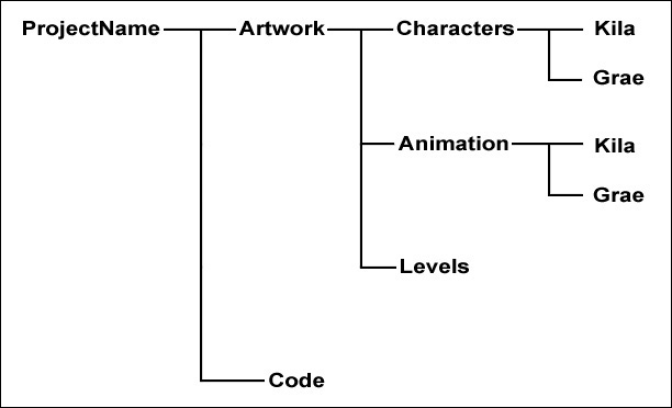
As good as Alienbrain is, it does not set up a directory structure for you. The leads on your team should establish this so that everyone knows where everything is at any given time. The directory framework can be as simple as the structure seen in Figure 2.1.
Preparing the Work Environment
Now that you know where to store your artwork, you can begin to prepare your working environment.
Scanning in the Model
First, you need to scan in your model sheet. By having these images available on your computer, you can import them into Maya and use them as a guide when you begin to build the model. Many developers find this arrangement to be a much better way to work because you can ultimately create a more precise model. Attempting to model from memory or by referring to hard copy references will ultimately lead to errors, and the proportions of the final models will likely be off.
You don’t need the scanned image to be huge, but it should retain most of the details that exist in the artwork. Scan in the model sheet at 100% or a resolution of 300 dpi; this is quite big, but it’s easier to shrink the image later on than to enlarge it. In addition, scanning it higher and then reducing it will give you a better-quality image than if you initially scan at a lower dpi.
Preparing the Scanned Image
When you take the image into Photoshop (or your preferred digital imaging package), you first need to rotate it, in this case 90 degrees counterclockwise. Save the rotated image now for use as reference.
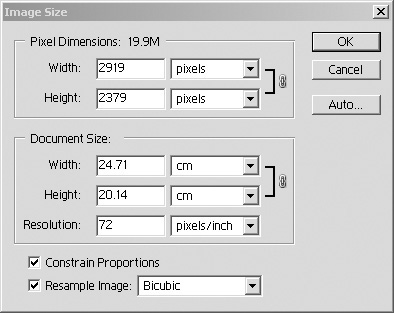
Once all that is done, you can shrink the image. All you need to do is adjust the ppi (pixels per inch); this will scale the overall image (Figure 2.2).
Note
Make sure Resample Image is enabled, If you leave this option unchecked in the Image Size dialog box, changing the dpi (dots per inch) does not alter the pixel resolution of the image (or its storage size on disk). It only affects the size of the image when it is printed.
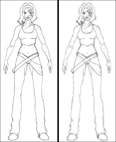
Adjusting an image to 72 ppi usually gives an acceptable result. When you need to work with a better, more detailed image, play around with the ppi until you have something acceptable. I recommend using a lower resolution in order to consume less memory on your machine, but you do not want to end up with an image so small that you can’t make out any details. See Figure 2.3 for an example of a good and a bad reduction.
Storing the Image
Now that you have your image stored with a resolution you can work with, you can chop it up and store the pieces (Figure 2.4). An ideal place to keep them would be in a Scans directory inside the main scene folder. These pieces will then be imported into Maya later as image planes, guidelines for modeling our characters.
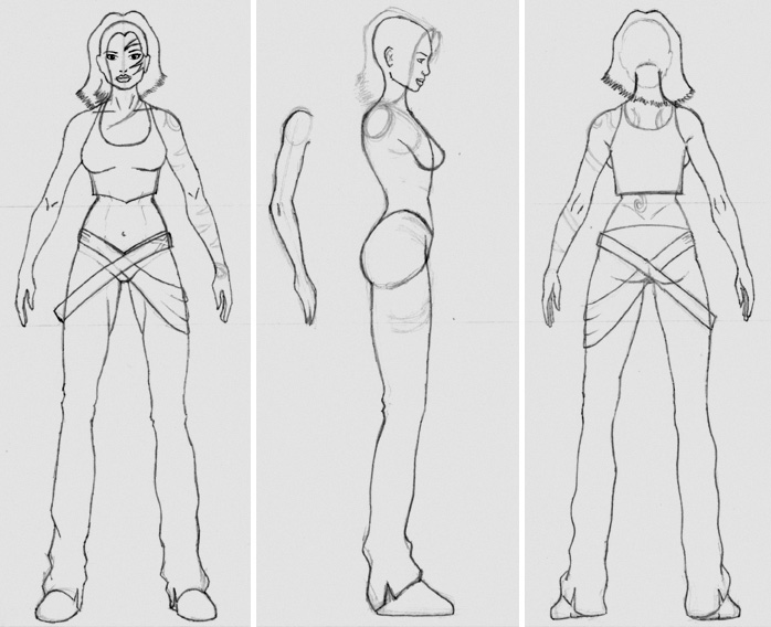
To store the pieces of an image, normally you would follow the directory structure dictated by your project manager, but for this book’s project we will use the file system found on the book’s CD. For this chapter, our characters will be stored in the directory Project Files/02. To keep things tidy, I have added a folder called Scans. Place the image pieces in here, along with the initial image scan (MainScan.tif). Let’s call the cropped images KilaFront.jpg and KilaSide.jpg—there’s no need to crop the rear image as we won’t be importing it into Maya.
Tip
Making sure the images are the same height, as well as keeping the head and other body parts in line, will help when working with them in Maya.
With the images cropped, stored, and ready, we have done all our external preparation. Next, we will move into the Maya program, so let’s take a look at the basic tools it has to offer.
Getting Started in Maya
We are now ready to load Maya and prepare it so we can begin modeling. But first let’s have a look at Maya itself. In case you don’t have Maya, you’ll find Maya’s Personal Learning Edition on the CD.
Maya’s Learning Movies and Tutorials
When you start Maya for the first time, you will be presented with the Learning Movies window seen in Figure 2.5. These one-minute movies cover some of the very basic elements in Maya, from moving and manipulating objects, to simple keyframe animation.
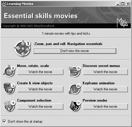
I recommend that you watch these movies before you proceed in this chapter. If you have already skipped past the Learning Movies window, you can reopen it by going to Help > Learning Movies.
If you have time, I also recommend looking at Maya’s built-in tutorials (Help > Tutorials). These cover every aspect of Maya and go beyond the fundamentals in the Learning Movies to show more advanced areas such as expressions and MEL (Maya Embedded Language).
Navigating with Menu Sets, Marking Menus, and The Hotbox
There are various ways to navigate the menus in Maya. Each person has their own preference, but you will no doubt use every method at some point in your work with Maya.
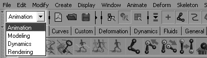
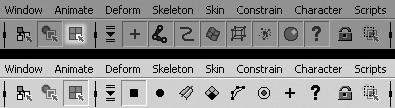
Across the top of Maya’s user interface is the main menu bar. This menu can be changed, depending on what area of Maya you are working in, by using the menu sets. The menu sets are located at the left of the status bar (Figure 2.6). You can change among the Animation (F2), Modeling (F3), Dynamics (F4), and Rendering (F5) menu sets. Each group opens up new tools specific to that job.
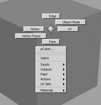
Right-clicking an object will open up a marking menu, Maya’s term for a contextual menu (Figure 2.7). These menus give quicker access to some of the tools you will commonly use with that object—for example, component selection.
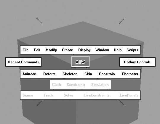
The third method is the hotbox, which contains every menu and menu item available in Maya and is fully customizable to suit your needs. When you want quick access to any menu without having to change menu sets, or if the menu you require is hidden, simply hold down the spacebar to open up the hotbox (Figure 2.8). To the right of the hotbox are the Hotbox Controls, where you can customize the appearance and contents of the hotbox.
Now that you have some basic knowledge of Maya and its user interface, we will see how to make sure Maya is configured correctly, before we begin to model.
Setting up Maya Preferences
Although the majority of Maya’s default preferences are fine for most of what we’re doing we will alter a few now to help us later. It’s important to follow these steps so we’re all working the same way.
1. Go to Window > Settings/Preferences > Preferences to open the Preferences window (Figure 2.9). This screen contains all the global preference settings in Maya.
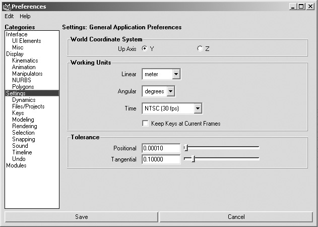
The first important setting to establish is the choice of units you are using (the scale you will be modeling to). It’s important to make sure that everyone on the project is using the same units; differing scales can cause major problems down the line, especially when rigging and animation are involved.
2. In the Categories panel on the left, select Settings and see what the working units are currently set to. In Figure 2.9, you can see that we will be working in meters and animating at 30 frames per second. Of course, these settings may vary depending on the project you are working on.
Note
For this book we will be using meters, but feel free to work in whatever units you are comfortable with. Just remember to make the appropriate corresponding adjustments to any of the measurements or values you use from the book.
3. While in the Preferences window, select the Interface category. Make sure Open Attribute Editor on the right is set to In Separate Window. This setting will ensure that we are working in the same environment for the discussions in this book; otherwise, some sections may be confusing.
4. Once you have finished setting up all your global Maya configurations, click Save.
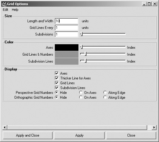
5. Then go to Display > Grid in the main menu and click the options box to open the Grid Options (Figure 2.10). In the Size section, setting the Grid Lines Every and Subdivisions to 1 will set each square on the grid to represent 1 meter (or whichever unit you are working in). Length and Width dictate how far your grid expands across your virtual world.
The Maya environment is now configured for our project. Remember that your settings should be the same as everyone else’s on the project.
Next, you must tell Maya where you wish to work. You can do this by using Maya’s projects. In Maya, you can work in a variety of file types and formats. By creating a project, you create subdirectories under a parent directory in which to store everything. This is Maya’s way of combining in one place all the files relevant to the current scene.
6. You can, if you like, ask Maya to create a directory structure and a new project for you by going to File > Project > New (Figure 2.11).
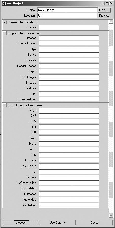
Here you can specify a name and a location for the project. Clicking Use Defaults at the bottom will automatically fill in the rest of the New Project window with names for the corresponding directories. If you do not want all the directories created, you can simply leave them blank and Maya will ignore them. Once you are happy with the project structure, click Accept. Maya will build the specified directories for you and set the new project to be the current one.
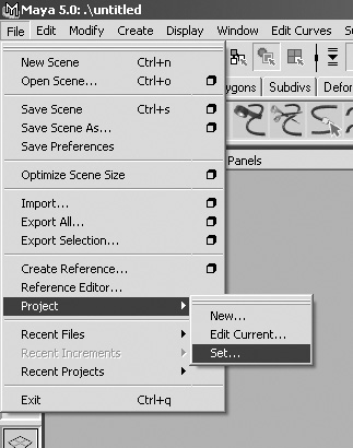
If your directory structure is already in place, as it should be, another way to set the current project is by going to File > Project > Set (Figure 2.12). Here you simply point to the directory you wish to work in, and it’s set.
7. The final work environment option to set is found in the Polygons > Tool Options menu. In that menu, make sure Keep Faces Together is activated.
As we progress through the book, we will perform operations that would otherwise involve our having to set this manually afterward. Setting it here means it is now set globally, saving us work later.
Importing to Maya
The final part of our preparation for modeling is to import the images we scanned and cropped earlier, bringing them into Maya’s panels so we can use them as guides.
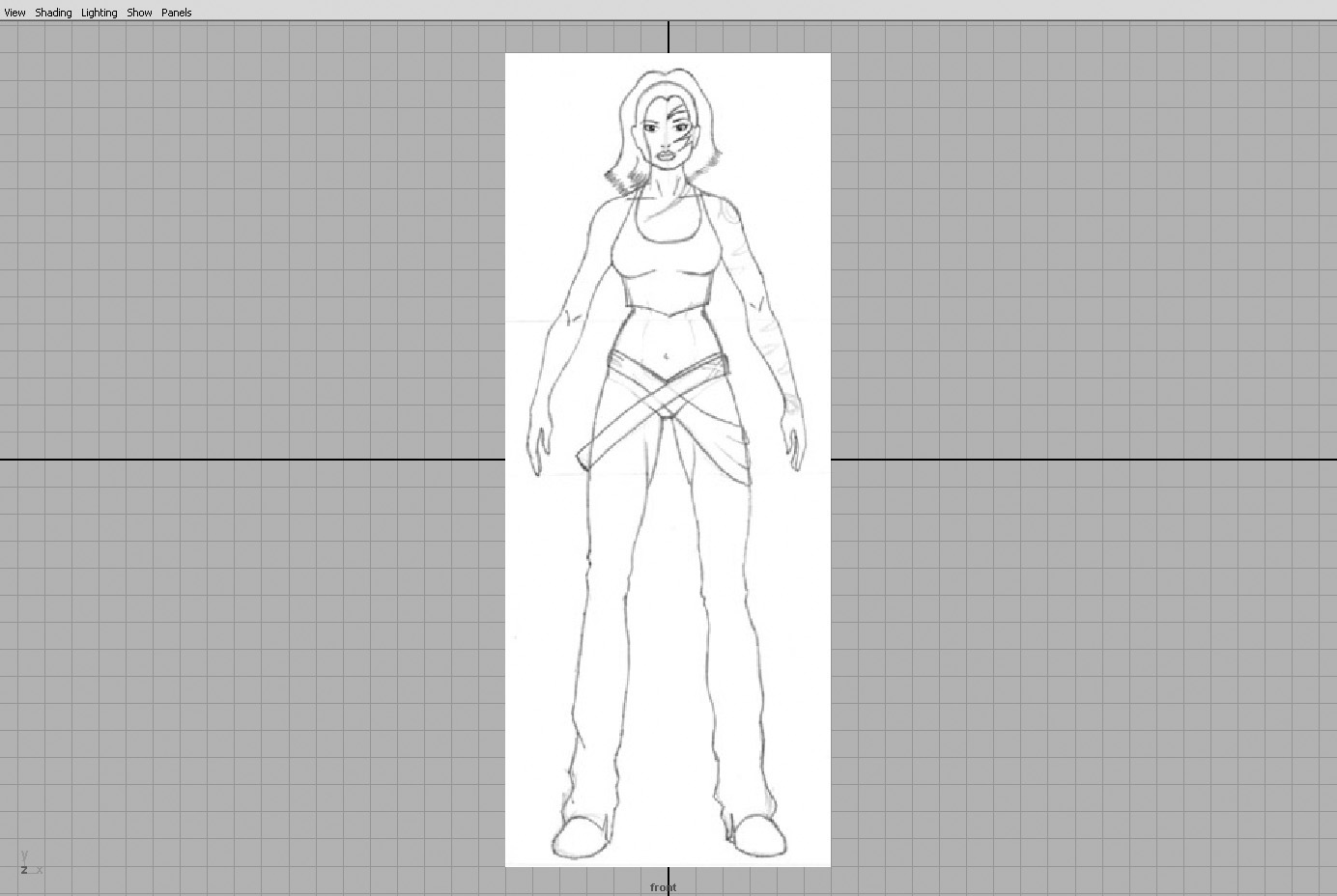
1. To import an image into the front view, at the top of the panel, select View > Image Plane, and click Import Image to open up the browser. You have already set your project, so the browser will automatically open in the correct base directory, enabling you to select the images we created earlier. For this view we will use the file KilaFront.jpg (or you can use KilaFront.tga), which is in the Scans directory.
Note
To switch views simply go to the Panels menu item in the current view panel and select the appropriate camera.
As you can see from Figure 2.13 the image plane is quite large. We know that each grid square is equal to one meter, so at this setting Kila would be 30 meters tall. We know from the character details we gathered earlier that she is 1.7 meters tall, so let’s change her size.
2. If you have not selected anything else at this stage, the image’s attributes will be available in the Channel Box under a heading of imagePlane1. Otherwise, if you need to make the attributes available, select View > Image Plane again. Notice that a new option is available, Image Plane Attributes. Move your mouse over this to reveal the current panel’s image planes. At the moment, you should have only one, called imagePlane1; select this. A new window opens, holding the options available for this image plane; you should also see it available in your Channel Box.
3. Set the Width and Height attributes to 1.7, and she will scale down to the size we need.
4. Now do the same for the side view. Import the image called KilaSide.jpg (or use KilaSide.tga) and resize it to 1.7. When you’re done, switch to the perspective view (Figure 2.14) to see how things look so far.
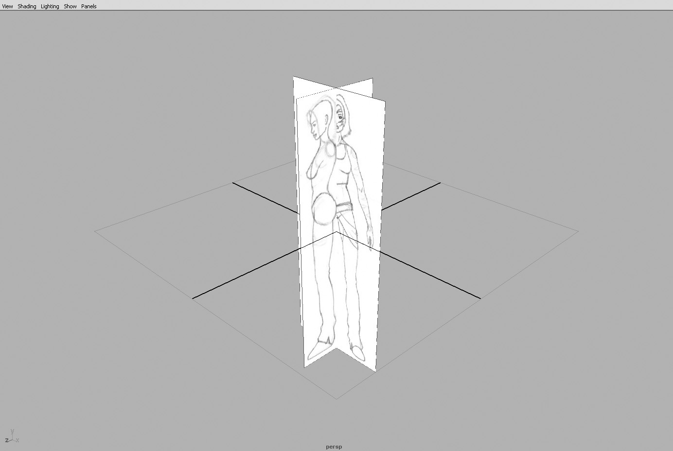
5. Looking through the perspective view now, things might seem a little confusing, but this can be fixed. We simply need to move the two images so that they do not intersect.
Select the side image by dragging the mouse over a corner of the image plane. Look in the Channel Box, which now shows the attributes available for the side view (Figure 2.15). At the bottom, under the heading Inputs, you can see the image plane, named imagePlane2.
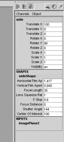
6. Click imagePlane2 to reveal the image plane’s options. Select Center X and set it to –0.35, which will move the image slightly to the left. Type -0.2 into the Center Z input box, which will move the image forward.
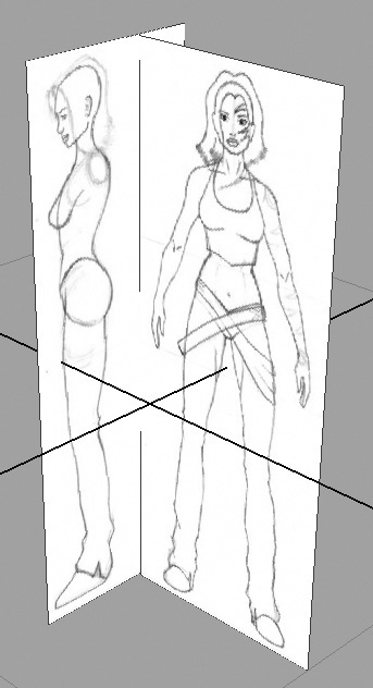
Play around with these settings for both images until you are happy with their positions. You should end up with something resembling Figure 2.16, with the images no longer intersecting.
Working with the Layer Editor
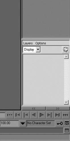
Before we finish this section, we will place the image planes into a layer. This will keep the scene tidy, as well as prevent the image planes from accidentally being selected and moved. You’ll find the Layer Editor in the bottom-right corner of the Maya interface, under the Channel Box (Figure 2.17).
1. First create a new layer by going to Layers > Create Layer, or click the Create Layer button on the Layer Editor’s toolbar (to the right and just under the menu).
2. A new layer is created, called layer1. Double-click this to bring up the Edit Layer options.
3. In the Edit Layer window, rename the layer to ImagePlanes. Set Display Type to Reference. This means whatever is in this layer will be visible but not selectable. Also, pick a color to represent the layer.
You can quickly hide everything in the layer by clicking on the V to the left of the layer name in the Layer Editor. This controls the visibility. The next indicator to the right, the R, represents the display type; you can click on this to cycle between Reference, Template, and Normal.
4. Select both the image planes, then highlight the ImagePlanes layer. With the layer highlighted, go to Layers > Add Selected Objects to Current Layer. The image planes will now be in the layer.
5. Save the file, calling it Kila_Start.mb.
Our preparation is now complete; we are ready to start building the Kila character.
Building a Placeholder Character
Using primitives (simple shapes such as cubes or cylinders) to create a basic “placeholder” version of the model gives the animators something to work with while the model is being completed. Depending on the project you are working on, getting a character approved can take time and could leave the animators waiting around for you, which in the long run will put them behind schedule. Generating this quick model will mean the animators can get to work early, transferring the animation to the final model at a later stage. Not only does this facilitate the workflow, it can also pinpoint any potential problem areas with the character’s proportions.
Basic Limb Creation
Using the file Kila_Start.mb that we have established, we can create some basic shapes and scale them to fit our character.
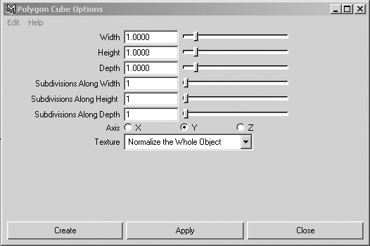
1. Load the file named Kila_Start.mb. Start by switching to the front view panel, and create a cube. To do this, go to Create > Polygon Primitives > Cube and open up the Polygon Cube Options dialog box (Figure 2.18). Make sure Width, Height, and Depth are all set to 1; then click the Create button.
2. Select the newly created cube; this highlights it in green, and a new manipulator should appear. (If this doesn’t happen, press W to get into move mode, or click the Move tool in the toolbox to the left.)
Take a look at Figure 2.19, which shows the four main manipulators; from the left, they are Move, Rotate, Scale, and the pivot point manipulator.
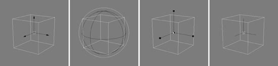
Each manipulator has four directions of movement or rotation, displayed in a particular color:
![]() Red moves or rotates around the X axis (left and right).
Red moves or rotates around the X axis (left and right).
![]() Green moves or rotates around the Y axis (up and down).
Green moves or rotates around the Y axis (up and down).
![]() Blue moves or rotates around the Z axis (forward and backward).
Blue moves or rotates around the Z axis (forward and backward).
![]() The yellow box/cube/circle moves or rotates the object relative to the camera’s view.
The yellow box/cube/circle moves or rotates the object relative to the camera’s view.
The use of each manipulator is pretty self-explanatory except for the pivot manipulator. This will allow you to move the pivot point on the selected object. You can access this by pressing the Insert key.
Tip
You can alter the size of a manipulator by using the + and – keys.
Tip
Using keyboard shortcuts is a good way to work more quickly. For the manipulators, use W to switch to move mode, E to rotate, and R to scale.
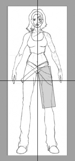
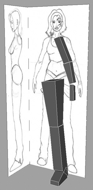
3. Using the appropriate manipulator, move, rotate, and scale the cube until it roughly fits Kila’s left thigh (Figure 2.20).
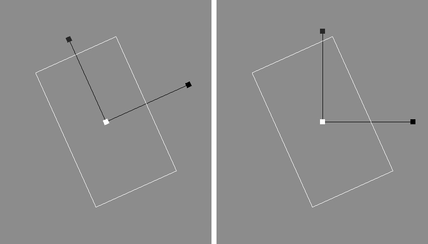
Note that it is important that you not freeze the object’s transformations at this stage; this would reset the object’s axis, making it more difficult to scale. Figure 2.21 (left) shows the axis as it should now be at this point in the procedure. We can quite happily scale this object; it will scale around the correct axis. On the other hand, Figure 2.21 (right) demonstrates the axis if it were reset. Scaling this object now would deform it incorrectly, making it difficult to achieve the desired shape.
Viewing the Geometry
![]() Wireframe (key 4)—Displays the edges of all the geometry in the view panel.
Wireframe (key 4)—Displays the edges of all the geometry in the view panel.
![]() Smooth Shade All (key 5)—Displays all the surfaces as smooth-shaded.
Smooth Shade All (key 5)—Displays all the surfaces as smooth-shaded.
![]() Smooth Shade Selected Items—Displays the selected objects’ surface as smooth-shaded (not shown in Figure 2.22).
Smooth Shade Selected Items—Displays the selected objects’ surface as smooth-shaded (not shown in Figure 2.22).
![]() Flat Shade All—Displays all surfaces and meshes as flat-shaded, faceted objects.
Flat Shade All—Displays all surfaces and meshes as flat-shaded, faceted objects.
![]() Flat Shade Selected Items—Displays the selected objects’ surfaces as flat-shaded/faceted (not shown in Figure 2.22).
Flat Shade Selected Items—Displays the selected objects’ surfaces as flat-shaded/faceted (not shown in Figure 2.22).
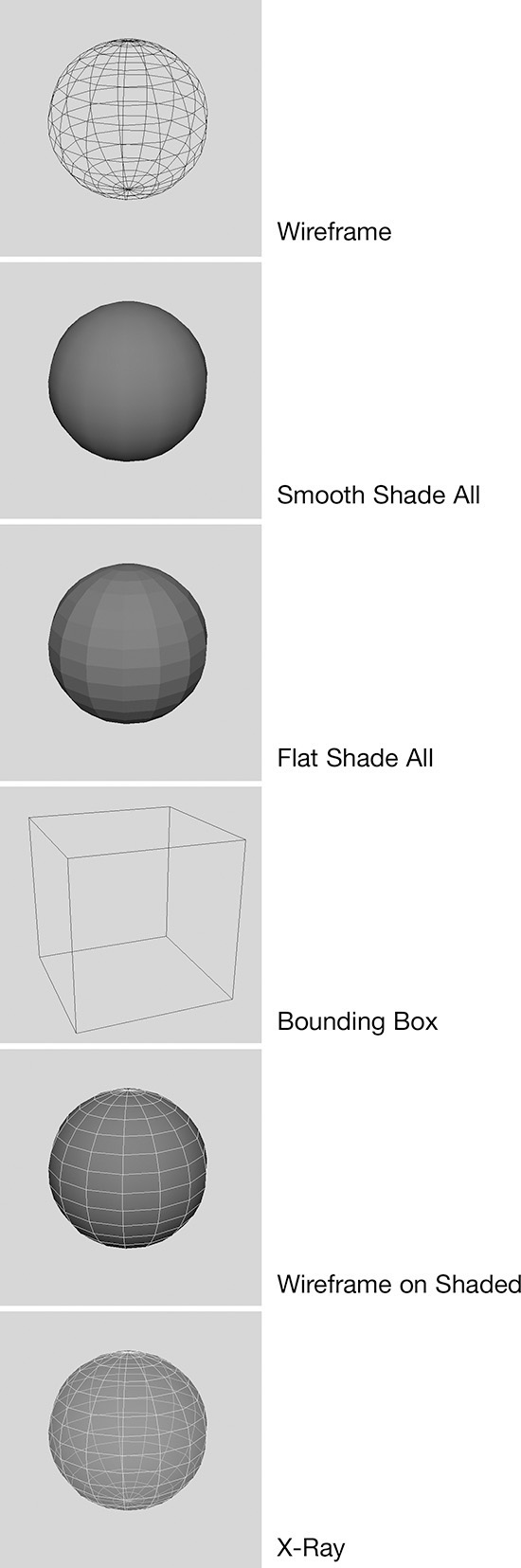
![]() Bounding Box—Shows the objects in the scene as boxes. This is mainly used to speed up Maya when you’re navigating complex scenes.
Bounding Box—Shows the objects in the scene as boxes. This is mainly used to speed up Maya when you’re navigating complex scenes.
![]() Points—Displays only the points (vertices) of objects in the scene (not shown in Figure 2.22).
Points—Displays only the points (vertices) of objects in the scene (not shown in Figure 2.22).
![]() Wireframe on Shaded—Combines the smooth-shaded and wireframe views.
Wireframe on Shaded—Combines the smooth-shaded and wireframe views.
![]() X-Ray—Shows all objects as semitransparent.
X-Ray—Shows all objects as semitransparent.
Tip
At this stage, you may find it easier to work in X-ray mode because it allows you to see through the geometry in the scene.
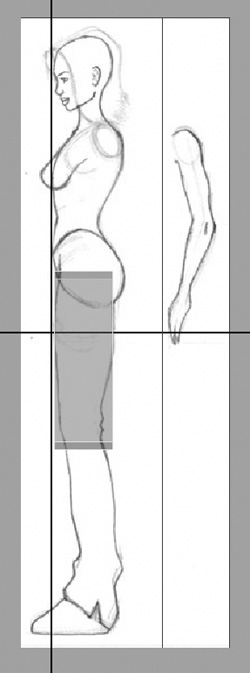
4. When you’re happy with the front view, switch to the side view and again manipulate the cube until it fits inside the thigh on the image plane (Figure 2.23).
At this point, you may wish to taper the lower part of the cube so it fits Kila’s thigh better, coming in slightly at her knee. The easiest way to achieve this is to work directly on the vertices. At the moment, you are working in Object mode, meaning you are selecting, editing, and manipulating complete objects. Vertices, like polygons, edges, and UVs, are all components of objects, so to edit components we need to switch to Component mode. There are a number of ways to do this:
![]() Right-click the cube itself. This will display a marking menu with options for opening up various components of the object for selection.
Right-click the cube itself. This will display a marking menu with options for opening up various components of the object for selection.
![]() Look at Figure 2.24 (top). I have highlighted the Select By Component Type button in the status line. Clicking this button will switch to Component mode, and the buttons to the right will change to represent the various components you can select.
Look at Figure 2.24 (top). I have highlighted the Select By Component Type button in the status line. Clicking this button will switch to Component mode, and the buttons to the right will change to represent the various components you can select.
![]() Pressing F8 will toggle between Object mode and Component mode. You can then select the component you wish to edit via the marking menu or the buttons in the status line.
Pressing F8 will toggle between Object mode and Component mode. You can then select the component you wish to edit via the marking menu or the buttons in the status line.
5. Switch to Component mode and open up the vertices for editing. You will notice that the box’s outline turns blue and the vertices are now colored purple. You can select the vertices at the bottom of the thigh and scale them inward, so that they fit nicely around her knee. Do this in both the front and side views.
To go back into Object mode, press F8, or you can right-click to bring up the marking menu and select Object Mode.
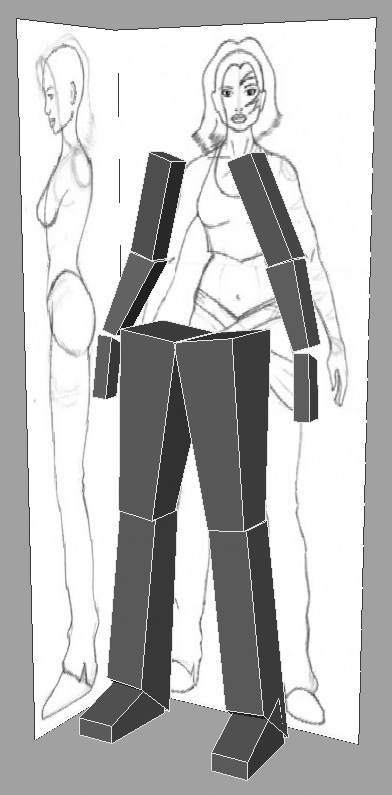
Continue using this method, creating basic cubes and manipulating them until you have Kila’s left side completed; just concentrate on her limbs for now. You should end up with something like Figure 2.25.
Create the Right Side
Kila’s right side will require much less effort than her left. With this model, we can simply mirror her left limbs to create her right side.
To do this we will group the current geometry. Grouping objects serves two purposes. First, it keeps the scene nice and tidy, making it easier to work with and navigate among the objects. Second, it allows us to manipulate a series of objects at the same time and with the same pivot.
When grouped, all the selected objects will be placed under a group node. This is the parent, and the objects are children. Whatever you do to the parent will be reflected in the children.
Tip
When objects are arranged in a group hierarchy, you can move up and down the chain using the arrow keys. The up and down arrows will “pick walk” up and down the chain. The left and right arrows will cycle through the objects on a particular hierarchical level.
1. Select the geometry you have created for Kila’s left arm and leg, and go to Edit > Group (or press Ctrl+G/Cmd+G). This groups the objects, placing the pivot for the group in the world’s center.
Tip
When selecting objects in your scene, remember these key-click combinations: Holding down Ctrl will remove items from the current selection. Holding the Shift key will toggle the items between selected and unselected. Holding down both Ctrl+Shift will add items to your selection.
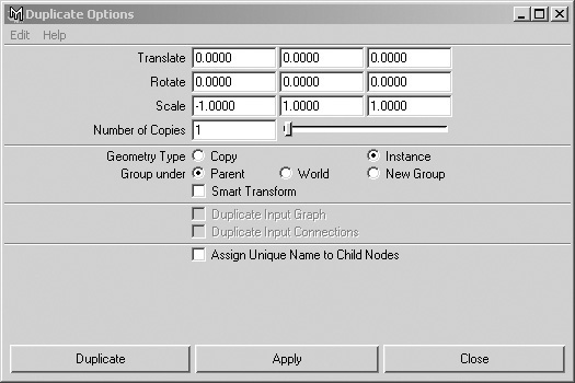
2. Create a duplicate. With the new group still selected, go to Edit > Duplicate and open up the options. Set the first input box next to Scale to –1 (this will mirror the duplicated geometry across the X axis). Also, make sure Geometry Type is set to Copy and Group Under is set to World. When you’re done, click the Duplicate button.
You now have two arms and two legs in the scene (Figure 2.26).
Finishing the Head, Neck, and Torso
To finish Kila, we need to create a head, neck, and torso. As before, we will use simple cubes for these. Create four cubes and manipulate them until they represent the neck, head, upper torso, and lower torso (Figure 2.27).
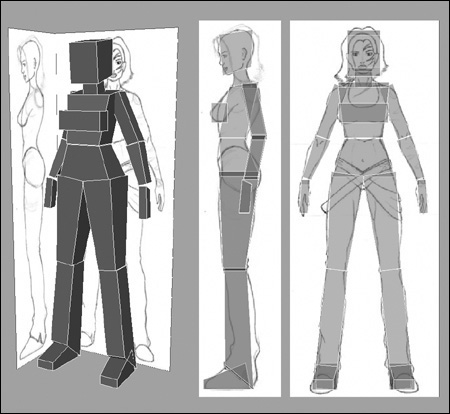
Divide the torso under the rib cage to give it a little more flexibility when it is animated.
Cleaning Up
She’s not much to look at, really, but this Dr. Who reject will be quite important in getting your characters animations started. All that is left at this stage is to clean up your scene and the History list.
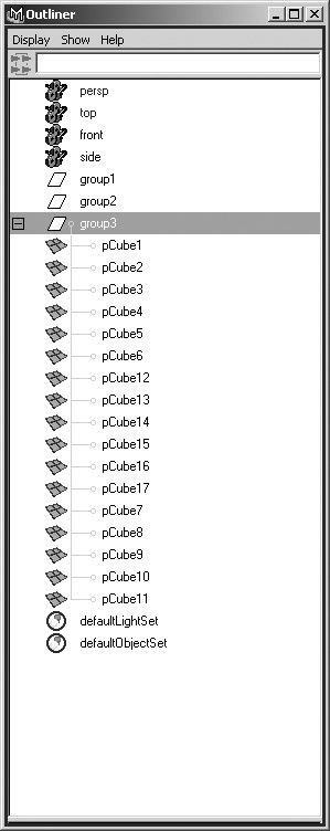
1. Select all the geometry that makes up your character and, as before, press Ctrl+G/Cmd+G to group everything into a nice tidy group. This should be named group3.
2. Open up the Outliner (Windows > Outliner), which displays the contents of the current scene. As shown in Figure 2.28, you should now have three groups named group1, group2, and group3.
You can also use Maya’s Hypergraph (Windows > Hypergraph) to organize the scene’s contents.
3. Delete group1 and group2, as these are no longer of use.
Tip
It’s important to stay on top of object naming. Remember that other people may use your work, so try and make it as easy for them as possible.
4. Next you will need to combine the objects into a single mesh. To do this, simply select all the cubes and go to Polygons > Combine. (For the first time, you will need to switch from the default Animation menu set to the Modeling menu set, or you won’t see the Polygons menu.)
As you have built this character, each action you have taken has created an extra node in the construction history. Look in the Channel Box when you have an object selected, and in the Inputs section you can see this history in the form of a long list. This is helpful for going back and editing things, but it also increases the file size and eats up your system’s memory. Having a long history could also throw Maya into terminal lock-up if operations such as Polygons > Combine, Edit Polygons > Extract, or Polygons > Smooth are executed on a complex model.
What we can do now to clean up the history is to bake it onto the model by first selecting the character and going to Edit > Delete By Type > History.
Alternatively if you wish to delete the history on every object in the scene simply go to Edit > Delete All by Type > History. This does not require anything to be selected beforehand.
With this version of the Kila model, the amount of detail is really up to you. You could use cylinders, as I will in the upcoming Basic Shape tutorial, to get in a bit more of the character’s shape. Or you could just stick to basic boxes. Whatever you choose, make sure you don’t spend too long on this version; it is only a placeholder character, after all.
You will find my version of Primitive Kila on the CD in Project Files/02, named Kila_Primitive.mb.
The Basic Shape for Kila
Now we’ll begin building our final model. As with Primitive Kila, we first have to block out the basic shape to get a good idea of the whole character’s shape and proportions. Don’t be too concerned with details at this stage; we will cover that stage of the modeling in Chapter 3.
Limbs and Torso
This time we will begin with cylinders rather than cubes. If you look at the human body from a geometric standpoint, it is made up of cylindrical shapes (except the head, which is spherical).
We know our polygon limit: 4500. With this in mind, we can estimate the configuration of the cylinders that will make up the left arm, left leg, and torso. Because the overall shape of the character is roughly symmetrical, we only need to model her left side. Then we can duplicate it and mirror it across at a later stage, saving half the work.
For a character that comes out at between 2000 and 3000 polygons, you’ll get a manageable number of polygons to begin with by starting with cylinders that have eight subdivisions around the axis and eight height subdivisions. This also leaves you with a smooth cylinder that won’t look blocky or faceted when viewed in the game. I have the luxury of more polygons for this character, so I am going to begin with a 10-subdivision setup.
The beauty of this method of creating characters is that it is fully scalable; you can begin with just a few subdivisions to create a lower-resolution character, or more subdivisions for a smoother character with greater detail, to use for rendering or FMV (Full Motion Video).
Left Arm Creation
Lets begin building the left arm.
1. Load your initial file, Kila_Start.mb.
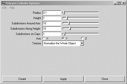
2. Create a cylinder (the first of three; you’ll need two others for the left leg and the torso). Go to Create > Polygon Primitives > Cylinder and open up the options.
3. Set the Radius to 0.1 and the Height to 1. Set both Subdivisions Around Axis and Subdivisions Along Height to 10 (Figure 2.31). Click the Create button.
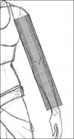
4. In the Channel Box, rename the cylinder to LeftArm. Then switch to the front view and move the cylinder up so that it lies over the character’s left arm. Keep the center of the cylinder (the center row of edges) near the elbow area of the arm. Rotate the cylinder so that it matches the orientation, and then scale the cylinder until it is about the same scale as the arm in the image plane (Figure 2.32).
5. Now that the geometry is in place, you can edit it further to achieve the shape you need to work with. Right-click the cylinder itself, bringing up the marking menu. Select Vertex to switch to vertex editing mode.
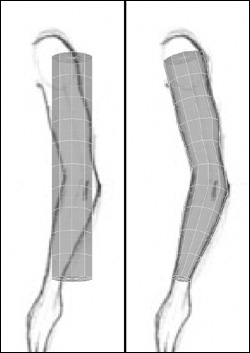
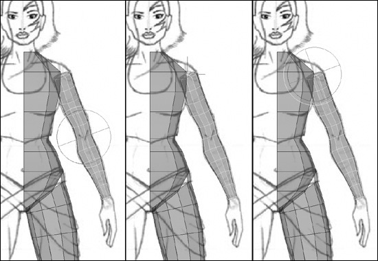
6. The cylinder is now blue, with all its vertices available to manipulate. Select each horizontal row in turn and scale it inward, using the red X axis manipulator, so that the outer vertices follow the lines of Kila’s arm. Make sure you only scale along one axis at a time. As you scale the vertices, feel free to move them to the correct position—but manipulate a single strip at a time; try not to edit each vertex individually. See Figure 2.33 for a comparison of the original arm with the scaled one.

Tip
You may find it useful to use the Lasso tool to select the vertices. This allows you to draw a line around the area you wish to select.
7. Next, switch to the side view and follow the same procedure. Manipulate the cylinder until it’s in the same position and orientation as the arm in the image. Right-click the cylinder and select Vertex from the marking menu to edit the vertices.
Arm Orientation
In addition to moving and scaling the vertices to match the image, you will want to rotate them to match the orientation of the limb. As the arm bends, it’s a good idea for the vertices to follow the contours of the limb. Don’t try and do the entire arm in one go—take your time and do each horizontal row, moving to the next one only when you are happy with your work (Figure 2.34).
1. Create a new cylinder using the same configuration as for the left arm. Name this second cylinder LeftLeg; then manipulate and scale it until it roughly matches Kila’s leg in the image plane (Figure 2.35).
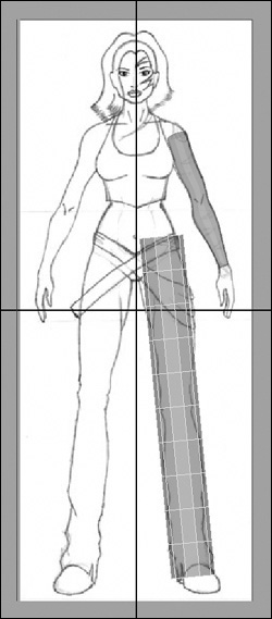
Again, remember to try and keep the central pivot of the cylinder around the pivot of the leg (the knee).
2. Right-click the cylinder and select Vertex from the marking menu. As before, scale each horizontal strip of vertices until the outer ones match the outline of Kila’s leg, making sure you only scale along one axis at a time (Figure 2.36).
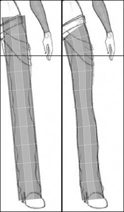
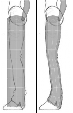
3. Once you are happy with the general shape of the front, go to the side view. Again, rotate and scale the strips of vertices so they follow the contours of the leg (Figure 2.37).
Creating and Positioning the Torso
The basic limbs are complete; now let’s tackle the torso. We will concentrate on the main body for now, and leave constructing the breasts for later.
1. We will follow the same procedure as before, so create a third cylinder, but this time set both the Subdivision Axis and Subdivision Height to 8. You need this configuration so that you will have a line down the center of her torso. Create this one and call it Torso.
2. Move the cylinder up along the Y axis and roughly scale it to fit the torso. At this point, try not to move it in any other direction.
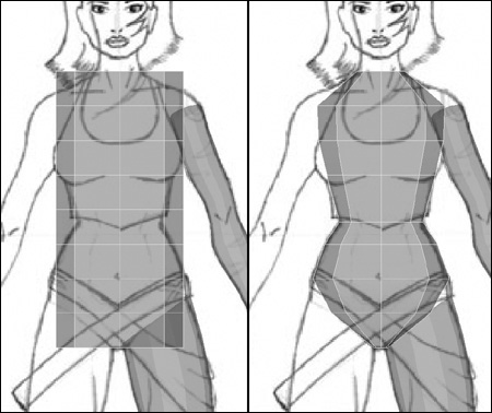
3. Just as you did with the arm and the leg, select each horizontal strip of vertices and scale it to match the torso in the image. Move the vertices up or down to match key areas in the sketch, such as around the hips (Figure 2.38).
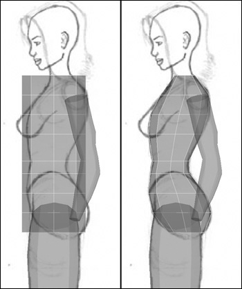
4. Switch to the side view and position the cylinder so that it lies over the image. Just move it along its Z axis, because moving it up or down will mean it won’t be aligned with the front image.
5. Manipulate the vertices so that the cylinder fits inside Kila’s torso (Figure 2.39).
Deleting Half of the Torso
We are not yet finished with the torso. Because we are only working on the left side of Kila, we need to delete half of her torso. (This is why it was important to have an edge down her center.)
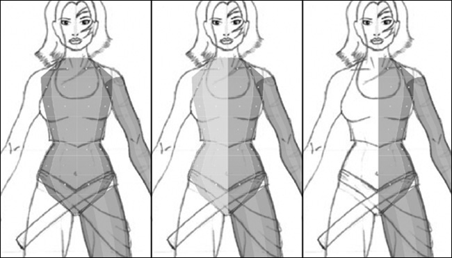
Right-click on the mesh again, but this time select Face from the marking menu. You will now be in face editing mode; you can tell because the mesh has turned blue and selection handles have appeared in the center of each face. Select Kila’s right side (your left), and press Delete. The faces disappear, leaving only the left side of her torso (Figure 2.40).
By now you can see the character starting to take shape. You should have a clean, grid-style mesh that fits the left side of your character (Figure 2.41). Ideally, however, what you want is for this to be one mesh, a single piece of geometry. We must combine these initial pieces and weld them together.
Moving the Pivot
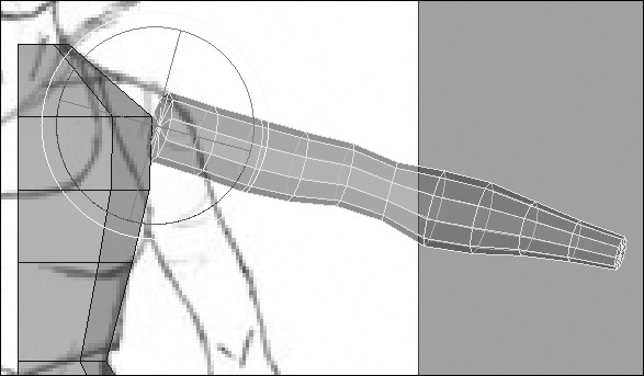
Eventually, you need Kila to be in a specific pose before you can attach a skeleton to her (more detail on this in Chapter 10). For now, we want to raise up her arms so they’re easier to work on. The problem is that the pivot for the arm is currently in the center of the cylinder. To raise the arm convincingly, we must move the pivot to where the shoulder is and rotate it from there.
1. Select the left arm. Make sure you are in rotate mode by pressing E. The Rotate manipulator will appear in the center of the arm, where the current pivot is.
2. To move the pivot, first press Insert; this changes the manipulator to represent the pivot position.
3. Move this pivot manipulator up to where the shoulder would be, and press Insert again to go back to the Rotate manipulator. See Figure 2.42 for an illustration of this manipulation.
Tip
To simplify the movement of the pivot manipulator, you can use the snap tools to position it exactly on a vertex. While moving the pivot point, press and hold the V key, which will snap the pivot to the nearest vertices.
4. Rotate the arm until it is raised slightly (Figure 2.43).
5. Before we can begin welding and stitching these elements together, we must combine them into one object. While you still have the arm selected, hold down Shift and select the torso and leg.
6. Go to Polygons > Combine, which will combine the selected objects.
7. We need to clean the model up a little, so remove the history by going to Edit > Delete By Type > History. Keep in mind that it’s a good idea to continue deleting the history and saving your model after you have reached a stage where you are happy with it.
Don’t develop the bad habit of saving over the same file each time you work on the character. Name saved files incrementally, for example Kila_01.mb, Kila_02.mb, and so on. This makes it easy to go back to a previous version should the worst happen.
Tip
Maya does have a built-in incremental file saver. Go to File > Save Scene and open the options, and you’ll be able to activate the incremental save. A directory called incrementalSave will be created, and all subsequent saves will be stored there.
Stitching Together
Now comes the fun part. We have to stitch these parts together by adding, splitting, and removing polygons as well as welding vertices.
Let’s start with the leg. First we have to remove the caps from the leg; the ends must be opened up so we can attach them. Plus we don’t want to end up with stray polygons existing inside Kila.
Select the faces at either end of the leg. Do this just as you have done earlier, by right-clicking the actual mesh, then selecting Face from the marking menu so you can select the faces shown in Figure 2.44. Then press Delete to remove them.
You can also do this on the arm now, so that you don’t have to do it later. Remember to do both ends, the shoulder and the wrist (Figure 2.45).
Returning to the thigh area, look for areas where vertices could line up and potentially be welded together. We know the leg has more polygons than the lower torso, but we can split polygons in order to connect them up. First, though, we must connect any that already line up. The first two lie down on the side of the hip. They both exist in roughly the same plane, so we can join them.
1. Select both vertices (Figure 2.46). Then go to Edit Polygons > Merge Vertices and open the options.
2. Set Distance to 0.1 and click Apply.
If nothing happens, it may be that the distance is too small, meaning the vertices are too far apart. Try again with a larger Distance setting. Close the options box after you’ve found a successful number, since we can use this distance for the rest of the welds.
Alternatively you can edit the node’s Distance directly in the Channel Box. Select the polyMergeVert1 name, and the node’s attributes will open below it, showing one named Distance. You can edit this, making it larger until the vertices snap together. They are now welded into a single vertex, as demonstrated in Figure 2.47.
Moving around to the left, you can skip the next vertex on the leg because there doesn’t appear to be a nearby vertex to weld it to. Notice that the one after that is in quite a good position to be welded to a close vertex on the torso (Figure 2.48).
Moving around to the back now, in a similar position to the front, you’ll see another two vertices that can be welded as shown in Figure 2.49.
Tip
If the image planes start to get in your way, you can quickly hide them by going to the view’s Show menu and unchecking Cameras. Alternatively, you can turn off the visibility on your ImagePlane layer.
Looking between the vertices you have welded, you should see two that appear to have nowhere to go. You could weld them to the vertices just above the hips, but they are too far away.
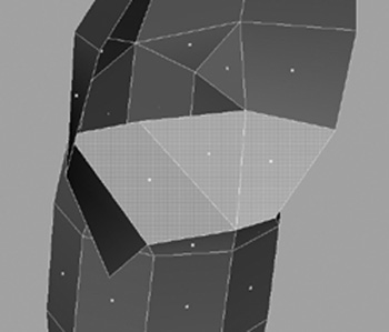
What you need to do now is create some new vertices in the geometry so that you can weld to these. Looking from the side, select the two faces on the lower torso and delete them (Figure 2.50), which will open up the hip area.
Now create some new faces to replace the ones you deleted, the difference being that these new ones will connect to the upper leg.
1. Go to Polygons > Append To Polygon Tool. This opens a tool that will allow you to create new polygons by stitching them onto the edges of existing ones. You should notice the edges of the mesh get slightly thicker when you activate this tool, to highlight the ones eligible to be appended.
2. Select one of the edges around a hole you just created. Purple arrows appear, highlighting other edges that you can now select to create a new polygon (Figure 2.51). The first time you clicked, you dictated the polygon’s starting position, and now you are telling Maya where you next want it to go.
3. Select another edge around the same hole. A pink triangle appears, showing the polygon you are about to create. Now press Enter on the keyboard to complete the polygon’s creation (Figure 2.52).
Follow this same procedure to create another three faces, connecting the leg to the hip and filling in the holes.
Tip
A quick way to repeat the last command is to press G or Y. This saves having to go back through the menus.
As you rotate around the mesh, you will notice that we have not removed the caps from the torso, so before you continue, select these top and bottom faces and delete them. This will also help you as you continue to weld the leg to the hip area.
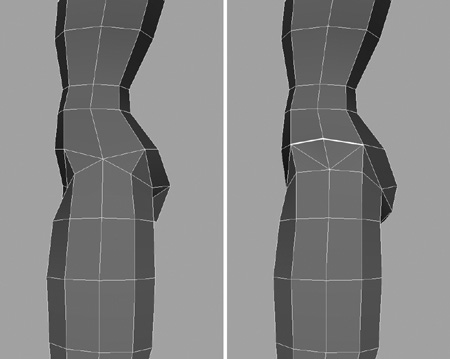
Following the same pattern described for the outer thigh, move around the inner thigh, skipping a vertex then selecting one. Match this vertex to the closest one belonging to the torso, and weld them as shown in Figure 2.53.
Move around to the back, and select and weld two vertices from there. Every other vertex gets welded, first the ones at the front and then those in the same area but at the rear (Figure 2.54).
You should end up with one vertex in the middle of the leg and two remaining on the torso. Don’t waste time welding these, because the vertices left on the torso belong to faces we need to remove. Select the faces as shown in Figure 2.55, and delete them.
Move around to the front of the figure and using the Append To Polygon Tool create two new faces, filling the gap at the front.
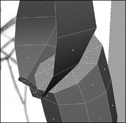
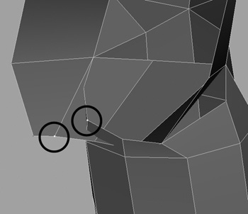
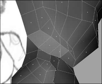
Now move around to the back, looking at her backside, where one polygon still remains. Instead of deleting this one, split it, making a new vertex that you can weld to. Go to Edit Polygons > Split Polygons Tool. Your mouse pointer will change to a sharp point, indicating that the tool is active.
When using the Split Polygon Tool, you must always start and end the cut on an edge. Select the edge at the upper-right of the face. A small square appears; holding the mouse button, move the square up to where the vertex is and release the button.
We now want to put a point on the edge that is closest to the final vertex of the leg, but shares the polygon of the edge we started on. Again, select the edge and hold down the mouse button until you are in the correct position, and then let go. The split is apparent as shown in Figure 2.56. Press Enter to complete the operation.
Note
The Split Polygon Tool will not snap to the position of the second vertex (nor should it), because it lies on an unconnected edge.
You now have a new vertex that you can weld to, so select both vertices and weld them.
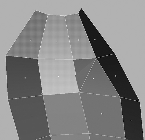
Our leg is now connected to the torso, but not very smoothly. We can fix this by moving around the mesh and manipulating the vertices until we get a better shape. Take care to keep checking your image plane guides as you go; it’s important you maintain the shape of the character. Keep moving around the mesh, checking the edges for stray polygons and anything that’s not smooth. Take your time, making sure the shape is perfect before you proceed. Don’t be afraid to split an area to smooth it out, as we did above the hip in Figure 2.57. At this early stage, you don’t need any details, but you do want to end up with a smooth mesh.
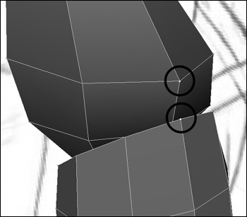
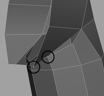
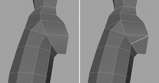
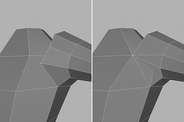
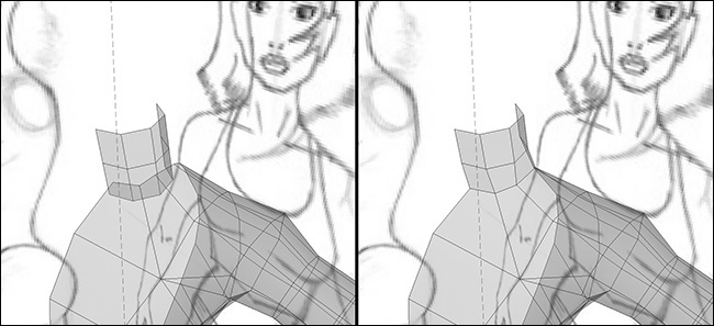
A wise move at this stage is to slowly rotate around the model and watch how the form turns. This can reveal undesired concavity in an inappropriately turned edge. As you rotate, notice the two edges just on her hip that are highlighted in Figure 2.58 (left). The current arrangement of these edges causes the polygons on either side to appear concave. We want them to be rotated, or flipped.
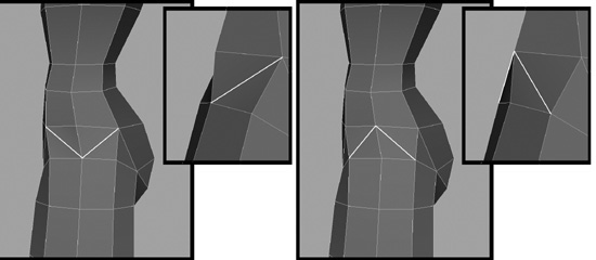
Normally we could use the Edit Polygons > Flip Triangle Edge Tool. We would select the edges we need to flip or rotate and then choose Flip Triangle Edge from the menu.
Unfortunately, if you try and do this, Maya comes up with an error: Warning: polyFlipEdge: Cannot flip texture border edge 218. The error occurs because two different types of texture-mapping coordinates exist on either side of the edges we are trying to flip. So what do we do? A quick solution is to manually delete the edges.
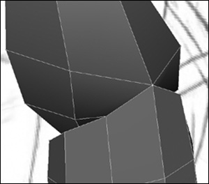
1. Go into edge editing mode (F10), select the two edges, and press Delete.
2. Now go in with the Split Polygon Tool and split the polygons correctly. You can see the results in Figure 2.58 (right).
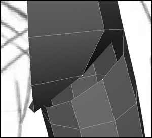
Kila’s thigh is at a satisfactory stage now, so let’s move on and attach her arm. Before you do, take a moment to clean the history, since this can slow things down if it’s not kept under control.
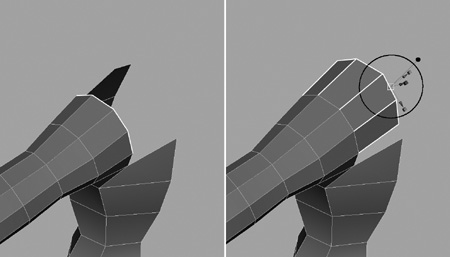
Looking from the front, we should probably start by scaling her arm up slightly around her shoulder. When a person’s arms are raised, the shoulders become more pronounced, so let’s do the scaling here, before we continue. Simply select the vertices around the top of the arm and scale them up globally, ever so slightly (Figure 2.59 middle).
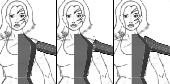
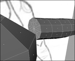
Select the edges at the same end of the arm. To do this quickly, convert the selection by going to Edit Polygons > Selection > Convert Selection to Edges. Now you have edges selected for you, but you only need the very end ones, so you need to deselect the others. You are still in vertex editing mode, so right-click on the mesh and select Edge from the marking menu. Holding down Ctrl, drag over the unneeded edges.
Kila’s arm is a little too far away, so you need to extend it so it meets the body. With the edges still selected, go to Edit Polygons > Extrude Edge. Drag the green arrow (Y axis) until the polygons have cut into the shoulder (Figure 2.59 right).
Note
Because we set Keep Faces Together earlier, the faces that have been extruded will automatically be welded together. Without this option set, the polygons would be divided and fanned out.
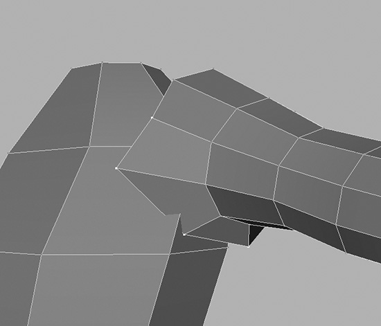
We can now start the work of stitching this area together. Clean it up a little first, by moving some of the vertices to a more suitable place, bringing them out of the torso mesh and into daylight as shown in Figure 2.60.
We could now start matching these vertices up with vertices on the torso, but a better idea is to move the ones on the torso to match the shoulder. First do the vertices in the armpit area. Weld these together as shown in Figure 2.61.
Moving to the front of the arm, select the three vertices right at the front, as seen in Figure 2.62, and weld these.
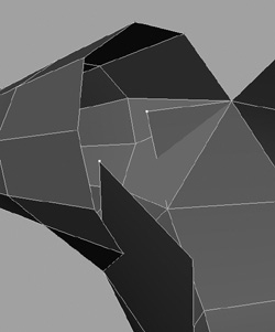
You will notice that we have a minor problem with a polygon cutting through another, but this can be rectified easily. To fix this you need to remove some faces now before proceeding. Select the three at the upper-rear of the torso, along with the center one from the row below it (Figure 2.63), and delete them all.
As shown in Figure 2.64, you should be left with two vertices sticking out; select them both. Holding down V, snap the selected vertices to the ones below them, and then weld them.
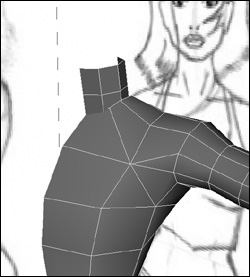
The area is cleaned up nicely now, and you can see things a bit more clearly. You need to go around the top now, and fill in the rest of the shoulder.
Select the top two and the rear two edges on the shoulder. Go to Edit Polygons > Extrude Edge, and drag the green arrow (Y axis) until the edges are nearly in line with what’s left of the torso, as shown in Figure 2.65.
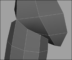
All that’s left to do now is fill in the holes at the front and back and do a bit of tidying. Before you do this, activate the Append to Polygon tool used earlier and fill in the holes; then spend some time cleaning up the area by moving vertices until the shape is correct. It’s a good idea to refer to a good anatomy book when you’re doing this, to make sure the shape matches actual human anatomy.
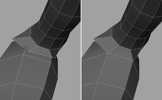
1. Right-click the mesh and select Edge from the marking menu to switch to edge editing mode.
2. Select all the edges on the mesh and go to Edit Polygons > Normals > Soften/Harden and open up the options.
3. Click All Soft, then Apply, and close the window.
Note
A normal is a line representing the direction perpendicular to a polygon’s surface. When you render polygons, the normals determine how light reflects off the surface.
Deselect the mesh and notice that it has been smoothed out—no more harsh lines (Figure 2.66). This gives us a clearer view of what the actual in-game mesh will look like.
Delete the history, and save your work as Kila_Combined.mb.
Head and Neck
At this early stage of development, we only need placeholder geometry—something we can build upon later—for the head and neck. The neck can be created using a simple cylinder; as with the torso, we only need half, but it’s easier to create the whole thing and delete half later.
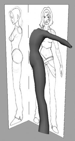
Create another cylinder, with Subdivision Axis set to 8 and Subdivision Height set to only 2. Position the cylinder so that it lies where the neck should be. You shouldn’t need to edit any of the strips of vertices for this section because it is such a small area and is pretty much cylindrical in shape to start with (Figure 2.67).
You need to remove half of the neck cylinder, along with the end caps. Right-click the neck’s geometry and select Face from the marking menu. Drag over the half you don’t want. Hold down Shift, select the top and bottom caps, and press Delete to remove them (Figure 2.68).
For the head, begin with a cube, but not a simple one like what we created for the primitive version of Kila. This time, set Subdivisions Width to 4, Subdivision Height to 4, and Subdivision Depth to 4.
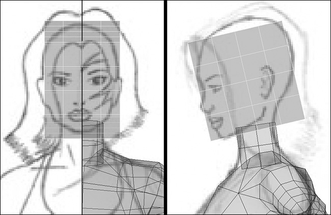
Move, scale, and rotate the cube so it approximately fits the size and orientation of the head in the image plane (Figure 2.69).
This time, delete half of the head first. Because you’re going to be editing the vertices, it’s easier to work on only one side.
In the side view, scale the vertices in so that the cube begins to resemble the image in the image plane (Figure 2.70).
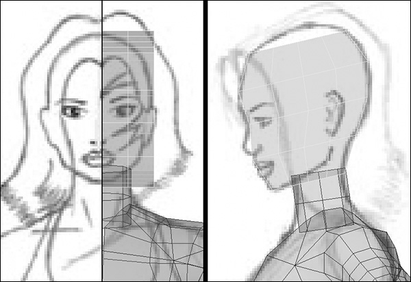
In the front view, select all the vertices on the right side of the cube. Switch to the side view, where you now need to scale the vertices in—because the head is rounder than it is square. First you need to smooth it out a little; when that’s done, move to the next row, scaling these vertices in slightly (Figure 2.71).
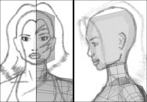
Now work on the vertices individually, manipulating them until the half-cube roughly resembles the shape of half a human head. Start in the side view, and then move around to the front, before finally working in perspective view. Remember to use your guides, and refer to some good anatomical reference material.
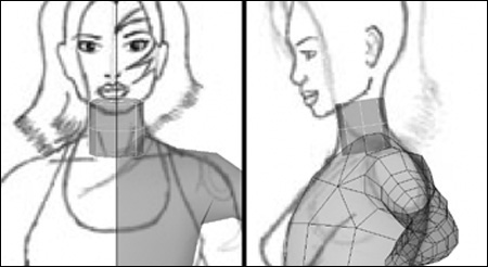
You may find it useful to smooth the head out a little by softening the normals, as we did before. Right-click the mesh, and select Edge from the marking menu to get into edge editing mode. Select all the edges on the mesh, and go to Edit Polygons > Normals > Soften/Harden and open up the options. Click All Soft, then Apply, and close the window; Figure 2.72 shows what you should have now.
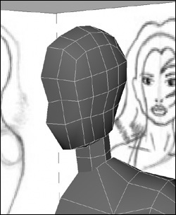
The final stage in creating the basic neck and head is to attach them to the body.
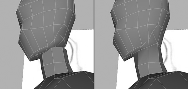
1. First let’s attach the neck; start by hiding the head. Select it and press Ctrl+H/Cmd+H.
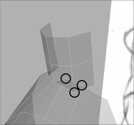
2. To combine the neck and body, use Polygons > Combine and proceed to weld the closest vertices. You may need to weld three together at once, as seen in Figure 2.73.
Once fully welded your geometry should resemble that in Figure 2.74.
3. Press Ctrl+Shift+H/Cmd+Shift+H to bring back the head; then combine this to the rest of the body. Again, try to weld the vertices that are the closest or that make the most sense to weld (Figure 2.75).
4. You will no doubt be left with some internal faces. It’s best to remove these before you proceed, and patch up any holes that are left under the chin (Figure 2.76).
5. Finally, clean up the area, first by selecting the edges and smoothing the normals. Then spend time working the vertices until you are happy with the final shape; your goal is shown in Figure 2.77.
Finish off by deleting the history on the mesh and saving your work.
If you haven’t already done so, now would be a good time to implement one of the mirrored instances I mentioned earlier in the chapter.
1. Select the mesh and go to Edit > Duplicate, opening up the options.
2. Set the first input box next to Scale to –1, and check Instance.
3. Click Duplicate to finish (Figure 2.78).
Now rotate around Kila and see if you can fix a few areas, filling her out and rounding her off (but don’t worry too much about it at this stage because we still have a few things to add).
Feet and Hands
It’s not necessary to bother with placeholder hands and feet. However, if geometry already exists for the hands and feet, you can add them just to get a sense of what the final character will look like (Figure 2.79).
Alternatively, you can include some primitive objects in order to achieve the correct proportions, giving a feel for the final character.
Other Body Parts
Kila’s basic shape is complete; now you can add any additional geometry. Skip her hair and clothing for now; you need to concentrate on getting the fundamental mesh completed and to a stage where you are happy with it. The one fundamental part remaining is the chest, so let’s add this now.
To simplify things, remove the mirrored instance you created earlier; just select it and delete it.
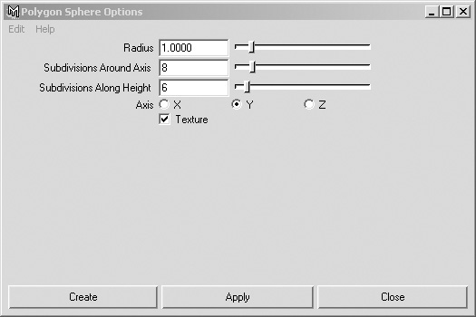
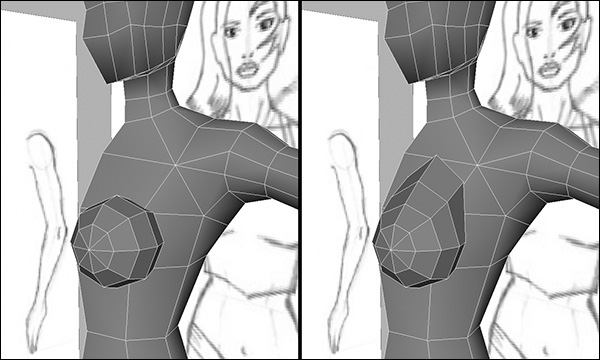
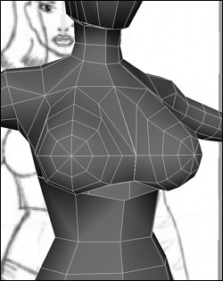
1. Create a sphere, opening up the options for Create > Polygon Primitives > Sphere (Figure 2.80). Set Subdivisions Around Axis to 8 and Subdivisions Along Height to 6.
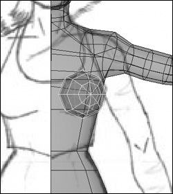
2. In the front view, position and scale the sphere until it covers her left breast. Do the same in the side view. In addition, rotate the sphere around its X axis by 90 degrees, and 20 degrees around its Y axis; you want the tip of the sphere pointing forward and slightly to the right (Figure 2.81). We do this so the sphere is pointing as a real breast would, with the nipple pointing outward slightly and not straight ahead.
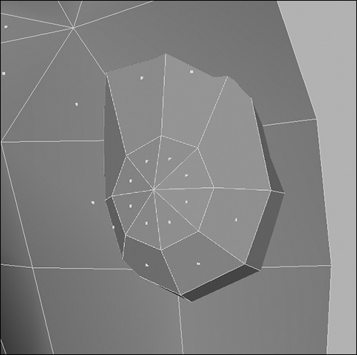
3. Combine the main mesh and the sphere. Then adjust the vertices on the top of the sphere to match the guide images (Figure 2.82).
4. Remove the back of the sphere (the faces that now exist inside the torso mesh), as seen in Figure 2.83.
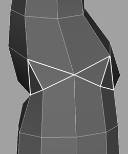
5. Your next step is to weld the sphere to the front of the torso. First, split the polygon across where her collarbone would be, and weld it to the top point of the sphere (Figure 2.84).
6. Remove the polygons from the front of her torso by selecting them and deleting them, leaving a large hole in their place.
7. Using the Polygons > Append To Polygon Tool, work your way around the sphere, filling in the holes and stitching the sphere to the front of her torso. As you work your way around you can weld the vertices at the very bottom of the sphere, this will allow you to create another polygon here. The result can be seen Figure 2.85.
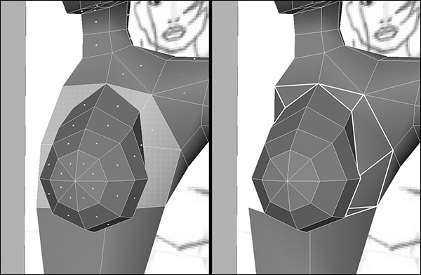
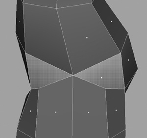
Our character is wearing a short top, so you will not be able to see the breasts as separate entities. This being the case, we can edit the inside of the sphere to bring the vertices out, creating the middle of the top—the part that bridges the front of her chest (Figure 2.86).
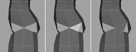
Create a mirrored instance at this point to help visualize how things are looking. You can see that we have a problem (well, not a problem to some)—her chest is huge! You need to reduce it to keep it in proportion to the overall design.
1. First, select all the vertices at the front of the sphere.
2. Double-click the Move tool to open up its options. Under Move Settings, select Move Normal (Figure 2.87).
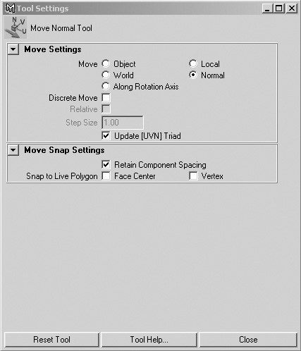
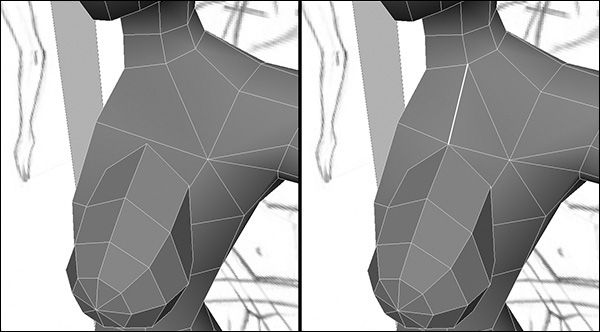
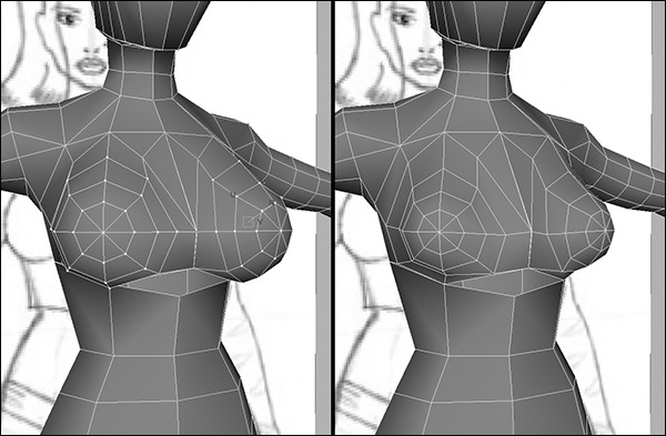
3. Move the handle via the manipulator labeled N. Notice that the vertices scale in and out while each one stays a relative distance from the other. Move them until you are happy with the size of her chest (Figure 2.88).
4. When you’re finished, open the Move tool’s options again and select Move Object in the Move Settings to reset the tool.
Although this is a good way to quickly reduce the size of Kila’s chest, you will need to spend some time afterward tweaking it back into an acceptable shape. Take as much time as you need to rework any other areas you are not happy with. Use the Split Polygon Tool if you need to add extra polygons to smooth her out (Figure 2.89).
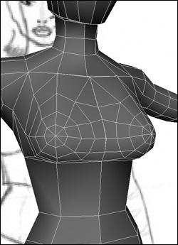
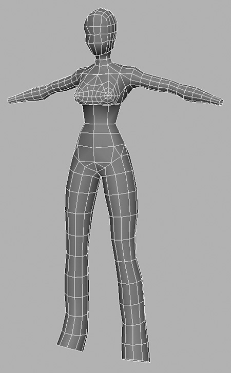
Once you’re completely happy with the entire shape, delete the history and save the file as Kila_Basic.mb.
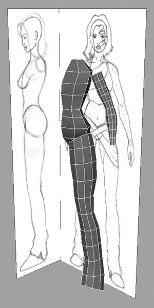
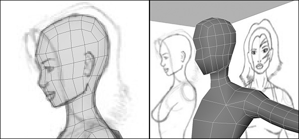
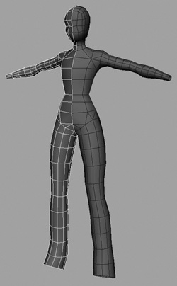
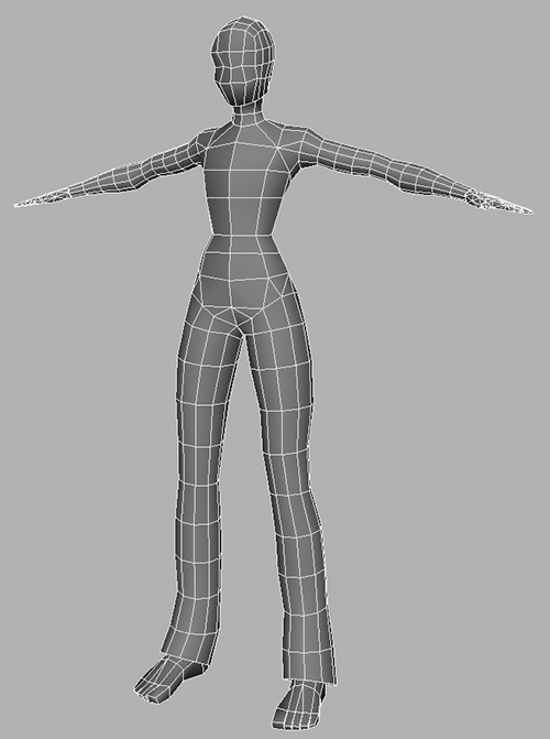
You now have an excellent basic model with correct proportions (Figure 2.90). You could use this mesh, along with placeholder hands and feet, as your primitive model, passing it on to be rigged and animated. It has a lot more detail than the box version and is closer to the final model.
The Morgue
Building up a collection of body parts is an efficient way of speeding up the modeling process as you create more and more characters. After you have completed a character, make sure the geometry is clean, optimized (more on this in Chapter 5), and ready to pass into a game engine. Once it reaches this stage, you can divide it up into specific body parts—hands, arms, feet, legs, torso, and head. Then store the parts in a special folder on your hard drive—what I like to call The Morgue—ready to be used on other characters.
This storage method isn’t just for the high-end versions of your characters; it is just as helpful for holding other levels of detail. In the end, you will have, for example, a complete set of hands at various resolutions. You can then import these into your scenes, adjust them as needed, and attach them to your characters, potentially saving days, if not weeks of work.
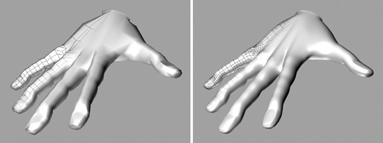
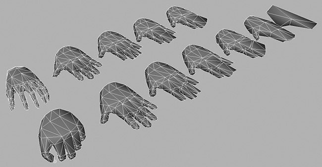
Figure 2.91 displays many different resolutions I have generated for the same hand. This file lies in my Morgue, ready for me to use on a new character. The models range from a fully deformable hand with working fingers, to a standard mitten-type hand typically used for lower-resolution models. Hands can take a lot of time to create—not only in their construction but in the way they deform. So once you have a good hand model, keep it safe. Even if you don’t use it as-is on another character, you can refer back to its topology.
On the CD you’ll find a directory called Morgue. In it I’ve placed a number of files from my own library. Feel free to use them either as you progress through the book or on your own personal projects.
Summary
We have successfully prepared our artwork and imported it into Maya, while examining a few of the environment settings. As we’ve begun the creation of the Kila model, we have experienced some of Maya’s basic modeling tools, most of which we will be using again in Chapter 3 as we add further details to the geometry.