
2
Highly Emissive d10 Metal Complexes as TADF Emitters with Versatile Structures and Photophysical Properties
Koichi Nozaki and Munetaka Iwamura
University of Toyama, Graduate School of Science and Engineering, 3190 Gofuku, Toyama, 930‐8555, Japan
2.1 Introduction
In the past few decades, luminescent metal complexes have been intensively studied because of their unique photophysical properties such as long‐lived phosphorescent states with high emission quantum yields [1–4]. The search for luminescent metal complexes containing heavy metals such as Ir(III) and Pt(II) has recently intensified. This was a consequence of the demonstration that phosphorescent emitters possess advantages over conventional fluorescent emitters, when developing organic light‐emitting diodes (OLEDs) [5–10]. Phosphorescent emitters can harvest singlet excitons (comprising 25% of the total), as well as triplet excitons (comprising 75%) generated during charge recombination in emitting layers. This results in near 100% internal quantum efficiency. Pioneering studies by Thompson and coworkers employed luminescent cyclometalated Ir(III) complexes, such as Ir(ppy)3 [7, 11]. Much subsequent effort has focused on exploring highly emissive d6 or d8 metal complexes suitable for phosphorescent emitters in OLEDs [12–16].
In recent years, there has been increasing attention given to luminescent complexes of d10 metal ions such as Cu(I), Ag(I), and Au(I) [17–23]. The main advantages of these complexes over d6 or d8 metal complexes are (i) the absence of low‐lying 3dd excited states that often quench the luminescent triplet states of d6 or d8 metal complexes and (ii) a large variety of coordination structures such as tetrahedral, trigonal planar, cubane, halogen‐bridged diamond core, etc. In particular, Cu(I) complexes have attracted considerable interest. Copper is abundant and therefore cost effective, and Cu(I) complexes have potential in optoelectronics [20, 24–31], sensors [32, 33], photosensitizers [34–38], photocatalysts [39–45], and upconversion sensitizer [46]. Cu(I) complexes with chelating bisdiimine ligands (N^N), [Cu(NN)2], have been widely investigated to understand the photophysics of pseudotetrahedral Cu(I) complexes. Promising OLED emitters include a family of [Cu(P^P)2], heteroleptic [Cu(N^N)(P^P)] complexes with the chelating bisphosphine ligand (P^P), and a halogen‐bridged dinuclear Cu(I) complex with a Cu2(µ‐X)2 core. Three‐coordinate Cu(I) complexes with trigonal planar structures have also attracted attention, because they can potentially avoid Jahn–Teller structural distortion. Such structural versatility of Cu(I) complexes results in their emission spanning a wide range of the visible spectrum.
Cu(I) complexes often exhibit thermally activated delayed fluorescence (TADF) (E‐type delayed fluorescence). This is fluorescence from singlet states generated by thermally induced reverse intersystem crossing (rISC) from triplet states [28, 47–49]. The photophysical properties of TADF of Cu(I) complexes are comparable (and sometimes superior) to those of highly luminescent cyclometalated Ir(III) complexes. Cationic Cu(I) complexes require counter anions to balance their charge and maintain electrical neutrality. However, neutral Cu(I) complexes have been synthesized using monodentate or bidentate anionic ligands. Some of the cation‐free Cu(I) complexes can be sublimed under vacuum, so are promising emitters for vacuum‐deposited OLEDs.
Recent reviews have highlighted the photoluminescence and electroluminescence of Cu(I) complexes [20, 22, 28, 29]. The current review focuses on the theoretical background and photophysical properties of TADF‐type d10 metal complexes as well as fast dynamics of flattening structural distortion upon photoexcitation of d10 metal complexes with a pseudotetrahedral structure.
2.2 Phosphorescence and TADF Mechanisms [50, 51]
Most transition metal complexes exhibit phosphorescence from their lowest triplet states [50, 51]. The intensity of this phosphorescence originates from intensity borrowing of the oscillator strength of fluorescence, through mixing of the T1 state and higher‐lying singlet states [10b, 50–54]. This arises from the strong spin–orbit coupling of the d electrons. The radiative rate constants of phosphorescence of third‐row transition metal complexes have reportedly reached 106 s−1, which is 104–107 times higher than those of organic compounds (typically in the order of 102–10−1 s−1 [55a]). The phosphorescent mechanism involves spin–orbit coupling of d electrons and dipole‐allowed fluorescent transition. Thus, larger radiative rate constants are often observed in complexes where the T1 and low‐lying singlet excited states have large contributions from the metal‐to‐ligand charge‐transfer (MLCT) electronic configuration. The radiative rate constants of phosphorescence (kr,T) can be calculated from the transition dipole moments of the singlet state components involved in the lowest triplet states using the expression
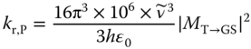
where ![]() is the emission energy of the T1 state in wavenumber and h and εo are Planck's constant and the vacuum permittivity, respectively. The transition dipole moment (MT→GS) originates from intensity borrowing of fluorescence through mixing of the T1 and higher‐lying singlet states (Sn), due to the strong spin–orbit coupling of d electrons:
is the emission energy of the T1 state in wavenumber and h and εo are Planck's constant and the vacuum permittivity, respectively. The transition dipole moment (MT→GS) originates from intensity borrowing of fluorescence through mixing of the T1 and higher‐lying singlet states (Sn), due to the strong spin–orbit coupling of d electrons:
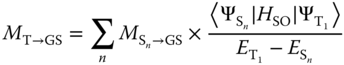
where ![]() denotes the transition dipole moment from Sn state to the ground state and the Ψ's and E's are the eigenfunctions and eigenvalues of the Hamiltonian without spin–orbit coupling, respectively.
denotes the transition dipole moment from Sn state to the ground state and the Ψ's and E's are the eigenfunctions and eigenvalues of the Hamiltonian without spin–orbit coupling, respectively.
The spin angular momentum must be exchanged with orbital angular momentum in the phosphorescent mechanism. This means that the MLCT electronic configurations in ![]() must involve different types of d orbitals. Thus, when S1 and T1 have the same electronic configuration, the conservation rule of angular momentum diminishes the direct spin–orbit coupling between the two states. In other words, intensity borrowing and intersystem crossing (ISC) between the two states would be inhibited and weakly arrowed via vibronic spin–orbit coupling [56].
must involve different types of d orbitals. Thus, when S1 and T1 have the same electronic configuration, the conservation rule of angular momentum diminishes the direct spin–orbit coupling between the two states. In other words, intensity borrowing and intersystem crossing (ISC) between the two states would be inhibited and weakly arrowed via vibronic spin–orbit coupling [56].
In the TADF mechanism, the T1 and S1 states are in thermal equilibrium, and triplet excitons are converted to emissive singlet excitons via rISC. Strong spin–orbit coupling is not required for the slow rISC process, which occurs in the microsecond or submicrosecond time scale.
When S1 and T1 are in equilibrium, the ratio of the populations of the S1 and T1 states can be approximated using a pseudo‐equilibrium constant (K), which can be expressed using their degeneracy (g1 and g3) and the energy difference (ΔEST) between S1 and T1:

By neglecting the prompt fluorescence component, the radiative rate constant (kr,DF) for TADF is given by Eq. (2.4) using the lifetime (τ) and emission quantum yield (Φ) of the TADF:
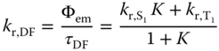
where ![]() and
and ![]() are the radiative rate constants of the S1 and T1 states, respectively. Eq. (2.4) shows that the radiative rate constant of TADF (kr,DF) is temperature dependent, which is one of the important characteristics of TADF. Because kr,DF is approximately proportional to kr,S1 and K, kr,DF increases with increasing kr,S1 and sharply increases with decreasing ΔEST. Ignoring the differing geometries of the S1 and T1 states, ΔEST is equal to twice the exchange integral (J). When the electronic configurations of both S1 and T1 are formed from electronic transition between the highest occupied orbital (φH) and lowest unoccupied orbital (φL), the exchange integral J is defined as
are the radiative rate constants of the S1 and T1 states, respectively. Eq. (2.4) shows that the radiative rate constant of TADF (kr,DF) is temperature dependent, which is one of the important characteristics of TADF. Because kr,DF is approximately proportional to kr,S1 and K, kr,DF increases with increasing kr,S1 and sharply increases with decreasing ΔEST. Ignoring the differing geometries of the S1 and T1 states, ΔEST is equal to twice the exchange integral (J). When the electronic configurations of both S1 and T1 are formed from electronic transition between the highest occupied orbital (φH) and lowest unoccupied orbital (φL), the exchange integral J is defined as
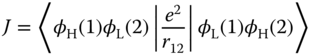
where e is the charge of an electron and r12 is the distance between two electrons.
Accordingly, the J integral is the coulombic repulsive energy between two electrons in the overlapped region between the highest occupied molecular orbital (HOMO) and lowest unoccupied molecular orbital (LUMO). Thus, the J integral increases with increasing spatial overlap of the HOMO and LUMO. The general strategy for reducing ΔEST is to employ a spatially separated HOMO and LUMO, such as in twisted intramolecular charge‐transfer excited states. For Cu(I) complexes, the electronic configuration of the lowest excited state would be charge transfer between orthogonal orbitals, i.e. dσ antibonding and π orbitals of aromatic ligands, resulting in a very small ΔEST.
The radiative rate constant kr,S is proportional to the square of the transition electric dipole moment (M), which is given as a matrix element of the dipole moment operator (![]() ) between S1 and GS. The moment M for S1→GS is often approximated by the integral between φH and φL:
) between S1 and GS. The moment M for S1→GS is often approximated by the integral between φH and φL:
Accordingly, a small spatial overlap of the HOMO and LUMO decreases the integral M and therefore decreases kr,S. However, the decrease in kr,S can be partially moderated by the larger mean distance (r) between the two electrons distributed on the spatially separated HOMO and LUMO. This theoretical argument has been experimentally validated, with various reported metal complexes and donor–acceptor systems involving charge transfer between the spatially separated HOMO and LUMO exhibiting efficient TADF.
The transition moment M for S1 → GS is the origin of the lowest energy absorption. Thus, the radiative rate constant kr,S involved in TADF can be predicted from the intensity of the lowest energy absorption band using the Strickler–Berg equation: [55]
where ![]() , n is the refractive index,
, n is the refractive index, ![]() is the excitation energy in wavenumber, ε is the absorption coefficient, and I (
is the excitation energy in wavenumber, ε is the absorption coefficient, and I (![]() ) is the emission spectrum measured in terms of relative numbers of quanta at each wavenumber.
) is the emission spectrum measured in terms of relative numbers of quanta at each wavenumber.
TADF is characterized by a (i) strong temperature dependence of radiative rate constant as described by Eq. (2.4), (ii) small energy separation between S1 and T1, and (iii) large radiative rate constant (kr,S > 1 × 10⁶ s−1) of the upper emissive state.
The energy separation between S1 and T1 can be determined through analyzing the temperature‐dependent radiative constants using Eq. (2.4). Alternatively, it can be estimated from the spectral shift of luminescence at ambient temperature, compared with that of the lower emitting state. It can also be estimated using theoretical calculations such as time‐dependent density functional theory (TD‐DFT) at the geometry optimized for T1 or S1. A large difference in the radiative rate constants at room temperature and 77 K is often employed as a convenient assignment of TADF. But this does not exclude the possibility of luminescence from thermally equilibrated triplet states. The radiative rate of the upper emissive state is the crucial factor for differentiating TADF from other mechanisms.
2.3 Structure‐Dependent Photophysical Properties of Four‐Coordinate [Cu(N^N)2] Complexes
The ground state of the d10 complex [Cu(N^N)2] prefers a pseudotetrahedral (D2d) molecular geometry, with the two diimine ligands orientated perpendicular to each other. Upon excitation to MLCT excited states, Cu(I) is oxidized to Cu(II) with a d9 configuration, affording a large structural change from a tetrahedral‐like structure to a flattened square‐planar structure, because of the pseudo‐Jahn–Teller (PJT) effect. Much of the pioneering work on copper(I) complexes was accomplished by McMillin and coworkers [57–61]. For example, [Cu(dmp)2]+ (dmp = 2,9‐dimethyl‐1,10‐phenanthroline) (1, Scheme 2.1) exhibits weak broad luminescence in a deep‐red region in noncoordinating solvents (Φ ∼ 2 × 10⁻⁴) (Figure 2.1). Complex 1 has been extensively investigated using spectroscopic techniques, such as ultrafast transient absorption [62, 63, 64b], time‐correlated single‐photon counting [50], fluorescence upconversion [64–67], and light‐initiated time‐resolved X‐ray absorption spectroscopy [62a, 66] as well as theoretical methods [68–71]. [Cu(phen)2]+ (phen = 1,10‐phenanthroline) does not exhibit emission under the same conditions as for complex 1. The bulky substituents at the 2,9‐positions of phen suppress the excited‐state flattening distortion and nonemissive deactivation, via a short‐lived exciplex formed with Lewis basic solvents.
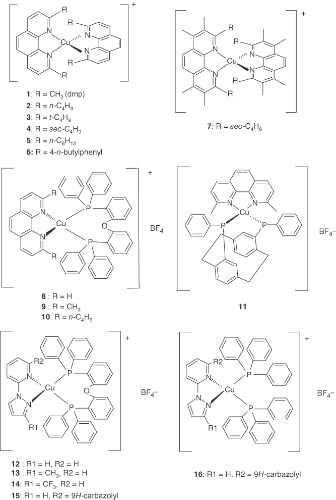


Scheme 2.1Molecular structures of Cu(I) complexes.

Figure 2.1 Absorption (red solid line), steady‐state emission (blue dotted line), and short‐lived component in the time‐resolved emission (amber solid line) spectra in CH2Cl2 at 298 K for 1 time gated from −20 to 150 ps. Source: Ref. [50]. Reproduced with permission of American Chemical Society.
In 1979, McMillin tentatively assigned a short‐lived (<1 ns) emission from [Cu(phen)(PPh3)2] (PPh3 = triphenylphosphine) in the solid state to prompt fluorescence from a singlet MLCT state [57a]. From the temperature dependence of the emission lifetime, they proposed that the origin of the emission was thermally equilibrated 1,3MLCT. Unfortunately, a more detailed analysis was complicated by difficulties in speciation by ligand disarrangement [72, 73]. In 1983, McMillin and coworkers attributed the emission of [Cu(dmp)2]+ in solution at ambient temperature to two thermally equilibrated excited states [58a]. The lower long lifetime state was assigned to 3MLCT. Two assignments were proposed for the upper emissive state. McMillin and coworkers assigned the higher state to 1MLCT, because of its high radiative rate constant of >1 × 10⁷ s−1 [58a]. However, an alternative assignment to a higher‐lying state spilt from a 3E state in D2d symmetry due to spin–orbit coupling was proposed, based on the emission lifetime and Stokes shift (i.e. the energy difference between the lowest absorption or excitation peak and the emission peak) [74].
Nozaki and coworkers directly determined the luminescence lifetimes and radiative rate constants of the upper state (13–16 ps) in 1 and its analogous complexes (2) using a time‐correlated single‐photon counting technique [50]. They assigned the upper state to the lowest 1MLCT state, based on the large radiative rate constant (>1 × 10⁶ s−1) of the prompt fluorescence and detailed theoretical considerations. The observed lifetime of 10 ps corresponded to ISC from 1MLCT to 3MLCT and was significantly slower than those for d6 metal complexes such as [Ru(bpy)3]2+ (<40 fs) (bpy = 2,2′‐bipyridine) [75, 76]. The spin–orbit coupling of the 3d electron in copper(I) is as strong as that of the 4d electron in ruthenium(II). The slow ISC in the copper(I) complexes was attributed to structural distortion, because of the PJT effect in the MLCT state. The distortion from the tetrahedral structure caused a large energy splitting (>6.8 × 103 cm−1) between the HOMO(21b2) and HOMO‐1(21b3), with large d orbital coefficients (Figure 2.2). Therefore, ultrafast ISC induced by a strong spin–orbit interaction (∼300 cm−1) involving the HOMO(21b2) and HOMO‐1(21b3), e.g. ISC from 11B1(21b2→22b3) to 23A(21b3→22b3), was energetically unfavorable, and the ISC would occur from 11B1(S1) to 13A(T1: 21b2 → 22b2) induced by relatively small spin–orbit coupling (<30 cm−1) due to small d orbital coefficients in ligand‐centered orbitals (22b2 and 22b3) (Figure 2.3a). The large energy splitting between HOMO and HOMO‐1 also reduced the mixing due to spin–orbit coupling between the lowest 3MLCT (13A) and 1MLCT with large oscillator strength (21B1, f = 0.1) (Figure 2.3b). This yielded a low radiative phosphorescence rate of ∼1 × 10³ s−1. Similar photophysical features were observed for Pt(0)(binap)2 (75) that has a pseudotetrahedral structure [51].
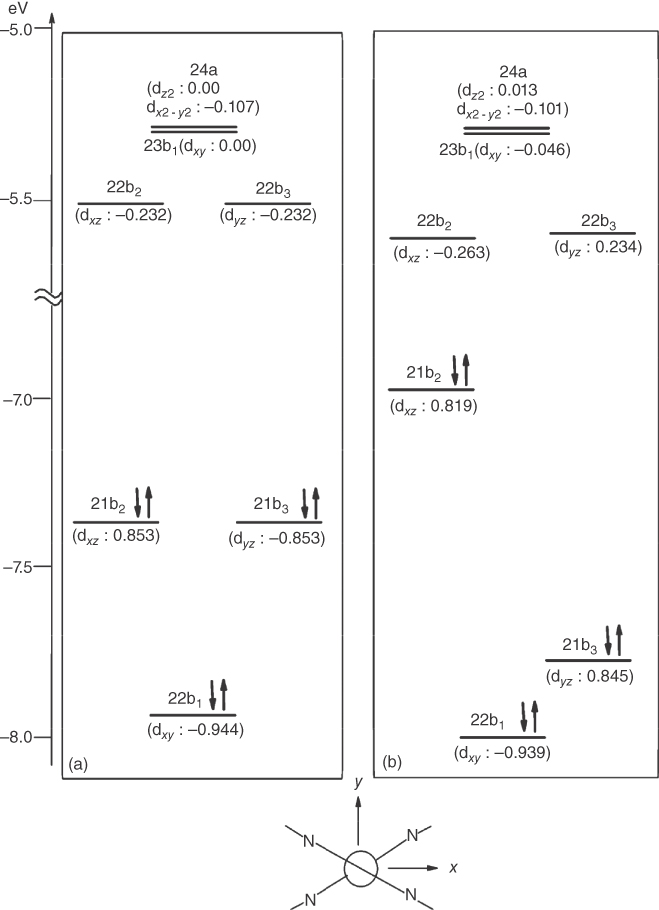
Figure 2.2MO energy levels of 1 at the ground state geometry with D2d point group (a) and those at the 1MLCT geometry (b). The numbers in parentheses are coefficients of d orbitals in each MO. The orientation of the molecule in the coordinate system used for calculation is shown at the bottom. Source: Ref. [50]. Reproduced with permission of American Chemical Society.

Figure 2.3Spin–orbit integrals between the lowest singlet state (11B1) and triplet states (a) and those between the lowest triplet state (13A) and singlet states at the flattened geometry of 1 (b). Values in figures are in cm−1. Source: Ref. [50]. Reproduced with permission of American Chemical Society.
A large energy separation between the HOMO and HOMO‐1 with different d orbital characteristics also reduces the zero‐field splitting (zfs) of the T1 state. Owing to spin–orbit coupling of the 3d Cu electron, the T1 state with MLCT character mixes with singlet and triplet MLCT excited states, which involve different d characteristics to that of the T1 state. This is the origin of the radiative rate of phosphorescence. The spin–orbit coupling also produces the splitting of the T1 sublevels (i.e. zfs). Yersin et al. reported that four‐coordinate Cu(I) complexes had very small zfs values (<2 cm−1) and low phosphorescence radiative rates (∼1 × 10³ s−1), c.f. complex 17 [10b]. This was attributed to the large energy separation of the HOMO and HOMO‐1 (>1 eV). In contrast, complex 67 had a relatively large zfs value (15 cm−1) and large radiative rate (∼1 × 10⁴ s−1), because the energy separation between the HOMO and HOMO‐1 was only ∼0.3 eV [77b].
Fluorescence from 1MLCT in complex 1 results in a large Stokes shift of ∼5.4 × 103 cm−1. DFT calculations by Nozaki revealed that the greater part of this Stokes shift originated from the large flattening distortion, due to the PJT effect. Increasing the bulkiness of the 2,9‐substituent phen ligands decreased the Stokes shift: 5400 cm−1 (1) > 5000 cm−1 (2, 5) > 4700 cm−1 (4) > 4200 cm−1 (3) > 3800 cm−1 (7) (Table 2.1). The lowest Stokes shift occurred when using the bulkiest sec‐butyl and tert‐butyl substituents [79].
Table 2.1 Photophysical properties of TADF of d10 metal complexes.
| In solution at r.t.a | In solid state or rigid matrix at r.t. | At 77 K | ΔEST b | References | ||||||||
| Complex | λem, nm (SS, 103 cm−1)c | Φ | τ (µs) | kr,DF (104 s−1) | λem, nm (SS, 103 cm−1) c | Φ | τ (µs) | kr,DF (104 s−1) | τ (µs) | kr,T (104 s−1) | (cm−1) | |
| [Cu(N^N)2]+ | ||||||||||||
| 1 | 748 (5400) | 0.0004 | 0.09 | 0.44 | 0.82 | 1800 | [58a, 78, 79b] | |||||
| 2 | 724 (5.0) | 0.0010 | 0.132 | 0.76 | 2.40 | 800 | [78] | |||||
| 3 | 615 (4.2) | 0.06 | 3.2 | 1.9 | 790 | [79a] | ||||||
| 4 | 690 (4.7) | 0.0045 | 0.38 | 1.13 | [79b] | |||||||
| 5 | 724 (5.0) | 0.0007 | 0.98 | 0.76 | 800 | [78] | ||||||
| 6 | 718 (3.5) | 0.0012 | 0.224 | 0.54 | 600 | [78] | ||||||
| 7 | 631 (3.8) | 0.063 | 2.8 | 2.28 | 2.6 | 1150 | [79b] | |||||
| [Cu(N^N)(P^P)], [Cu(P^P)(P^X)], etc. | ||||||||||||
| 8 | 700 (11.3) | 0.0018 | 0.19 | 0.95 | [73] | |||||||
| 9 | 565 (8.4) | 0.15 | 14.3 | 1.0 | d | [73] | ||||||
| 10 | 560 (8.6) | 0.16 | 16.1 | 1.0 | 800 | [25b, 73] | ||||||
| 11 | 558 (8.8) | 0.40 | 10 | 6.0 | 530 | 0.80 | 14 | 5.7 | 240 | 0.29 | 1000 | [77a] |
| 12 | 590 | 0.021 | 1.6 | 1.3 | 490 | 0.56 | 20.4 | 2.7 | 1450e | [80] | ||
| 13 | 536 | 0.45 | 11.9 | 3.8 | 465 | 0.87 | 12.2 | 7.1 | 1370 e | [80] | ||
| 14 | 540 (9.9) | 0.30 | 13.3 | 2.3 | 492 | 0.75 | 22.8 | 3.3 | 346 | 1450 e | [80] | |
| 15 | 518 (7.7) | 0.98 | 23 | 0.34 | 521 | 0.11 | 1450 | [81] | ||||
| 16 | 495 (6.8) | 0.45 | 134 | 4.3 | 671 | 0.092 | 1050 | [81] | ||||
| 17 | 535 | 0.09 | 1.3 | 6.9 | 436 | 0.45 | 20 | 2.3 | 610 | 1300 | [30] | |
| 18 | 500 | 0.02 | 0.5 | 4.0 | 447 | 0.90 | 22 | 4.1 | 450 | 1000 | [30] | |
| 19 | 498 | 0.08 | 1.8 | 4.4 | 464 | 0.90 | 13 | 6.9 | 480 | 0.20 | 650 | [30] |
| 20 | 609 (9.9) | <0.001 | 0.08 | 1.3 | 535 | 0.70 | 3.3 | 21 | 1200 | 0.83 | 1294 e | [82] |
| 370 | [77b] | |||||||||||
| 21 | 614 (10.0) | 0.005 | 0.13 | 3.8 | 800 | 1.1 | 1623 e | [82] | ||||
| 22 | 616 (8.8) | 0.02 | 0.35 | 5.7 | 300 | 3.1 | 1511 e | [82] | ||||
| 23 | 580 (9.1) | 0.02 | 521 | 0.52 | 1.7, 0.33f | 847 | 0.086 | 309 e , 467g | [83] | |||
| 24 | 494 (6.0) | 0.8 | 8.5 | 9.4 | 492 (6.0) | 0.8 | 4.0, 8.5 f | 132 | 0.21 | 800 | [84] | |
| 25 | 468 | 0.99 | 9.4h | 11 h | 36 h | 2.3 h | 940 | [85] | ||||
| 26 | 467 | 0.95 | 15 h | 6.3 h | 52 h | 1.8 h | 1070 | [85] | ||||
| 27 | 455 | 0.66 | 9.5 h | 6.9 h | 52 h | 1.4 h | 1170 | [85] | ||||
| 28 | 500 (8.6) | 464 | 0.82 | 28 | 2.9 | 350 | 600 | [86] | ||||
| 29 | 505 (9.2) | 477 | 0.99 | 29 | 3.4 | 237 | 600 | [86] | ||||
| 30 | 500 (8.2) | 479 | 0.83 | 25 | 3.3 | 292 | 700 | [86] | ||||
| 31 | 520 (9.6) | 471 | 0.84 | 37 | 2.3 | 258 | 700 | [86] | ||||
| 32 | 505 (8.0) | 481 | 0.87 | 25 | 3.5 | 437 | 700 | [86] | ||||
| Three‐coordinate [Cu(N^N)X], [Cu(P^P)X] | ||||||||||||
| 33 | 475 | 0.76 | 11 | 6.9 | 34 | 2.7 | 740 | [87] | ||||
| 34 | 575 | 0.73 | 18 | 4.1i | 21 | 3.8 | >3000 i | [87] | ||||
| 35 | 534 (7.9) | 0.43 | 4.9 | 8.8 | 517 | 0.38 | 4.6 | 8.3 | 2500 | 0.022 | 680 | [88] |
| 36 | 527 (7.7) | 0.47 | 5.4 | 8.7 | 512 | 0.55 | 8.0 | 6.9 | 360 | 0.24 | 810 | [88] |
| 37 | 517 (7.3) | 0.60 | 6.5 | 9.2 | 473 | 0.59 | 7.1 | 8.3 | 100 | 0.85 | 830 | [88] |
| 38 | 487 | 0.80 | 6.5 | 12 | 520 | 600 | [89] | |||||
| 39 | 519 (7.4) | 0.50 | 7.7 | 6.5 | 486 | 0.95 | 8.9 | 11 | 910 | 710 | [89] | |
| 40 | 592 | 0.24 | 1.4 | 17.1 | 488 (9.6) | 0.95 | 6.6 | 14 | 1100 | 0.96 | 690 | [90] |
| 41 | 546 | 0.15 | 1.0 | 15 | 500 | 0.95 | 5.0 | 19 | 1900 | 0.55 | 630 | [90] |
| 42 | 677 (4.5) | <0.01 | 0.9, 0.4 f | <1.0 | [91] | |||||||
| 43 | 658 (4.4) | 0.02 | 1.1, 0.6 f | ∼2 | 1200 e | [91] | ||||||
| 44 | 624 (3.2) | 0.15 | 3.7 | ∼4 | [91] | |||||||
| Binuclear {Cu2(µ‐X)2}‐core, etc. | ||||||||||||
| 45 | 667 (3.5) | 0.18 | 6.4 | 2.8 | 25j | d | [91] | |||||
| 46 | 533 | 0.6 | 1.5, 4.2 f | 2400 | [84] | |||||||
| 47 | 520 | 0.6 | 1.0, 4.3 f | 2300 | [84] | |||||||
| 48 | 502 | 0.8 | 2.5, 4.0 f | 50, 211 f | 664 | [84] | ||||||
| 49 | 559 | 490 (6.3) | 0.42 | 6.3 | 6.7 | 405 | 450 | [92] | ||||
| 50 | 551 | 482 (5.9) | 0.50 | 6.4 | 7.8 | 193 | 440 | [92] | ||||
| 51 | 541 | 488 (6.2) | 0.95 | 4.9 | 19 | 115 | 450 | [92] | ||||
| 52 | 506 | 0.45 | 6.6 | 6.8 | 220 | 0.45 | 460 | [93] | ||||
| 53 | 490 | 0.65 | 4.1 | 16 | 930 | 0.11 | 510 | [93] | ||||
| 54 | 464 (4.1) | 0.65 | 4.6 | 14 | 270 | 0.37 | 570 | [93] | ||||
| 55 | 465 | 0.65 | 5.6 | 12 | 250 | 0.4 | 630 | [93] | ||||
| 56 | 524 (2.1) | 0.57 | 11.5 | 4.9 | 336 | 786 | [24] | |||||
| 57 | 550 (4.0) | 0.49 | 11.0 | 4.5 | 90, 155 f | 740 | [94] | |||||
| 58 | 520 (4.6) | 0.59 | 11.0 | 5.4 | 97.6 | 710 | [94] | |||||
| 59 | 538 (6.4) | 0.67 | 15.3 | 4.4 i | 18.7 | >1800 i | [94] | |||||
| 60 | 537 | 0.81 | 6.5 | 12 | 32 | 2.8 | 400 | [95] | ||||
| 61 | 581 | 0.02 | 0.2 h | 10 h | 515 | 0.89 | 2.3 h | 39 h | [96] | |||
| 62 | 572 | 0.24 | 2.4 h | 10 h | 510 (5.4) | 0.99 | 1.92 h | 52 h | 480 | [96] | ||
| 63 | 589 | 0.14 | 1.7 h | 8.2 h | 542 (6.5) | 0.74 | 3.73 h | 20 h | [96] | |||
| 64 | 500 (6.3) | 0.84 | 1.76 h | 48 h | [96] | |||||||
| 65 | 507 (5.9) | 0.80 | 2.34 h | 34 h | [96] | |||||||
| 66 | 538 | 0.77 | 3.6 | 26 | 115 | 725 g | [97] | |||||
| 67 | 485 | 0.92 | 8.3 | 11 | 44 | 2.2 | 930 | [31] | ||||
| 68 | 501 | 0.52 | 12.4 | 4.2 | 84 | 1.2 | 950 g | [31] | ||||
| 69 | 484 | 0.76 | 7.3 | 10 | 51 | 1.8 | 1100 g | [31] | ||||
| Ag(I), Au(I), Pt(0), Pd(0) | ||||||||||||
| 70 | 505 | 0.32 | 2.2, 0.56 f | 574 | 1.3 | 199 e | [83] | |||||
| 71 | 610 | 0.12 | 1.7, 0.47 f | 52 | 3.5 | 405 e | [83] | |||||
| 72 | 760 (5.7) | 0.12 | 1.25 | 9.9 | 0.24 | 1150 | [51] | |||||
| 73 | 750 (5.8) | 0.32 | 2.6 | 12 | 0.24 | 1300 | [98] | |||||
| 74 | 690 (7.9) | 0.27 | 2.4 | 11 | 1.3 | 1400 | [98] | |||||
| 75 | 670 (8.2) | 0.38 | 3.2 | 12 | 0.33 | 910 | [98] | |||||
aIn deaerated solution.
bDetermined from temperature dependence of decay rate.
cValues in parentheses are Stokes shift (SS) in 103 cm−1 estimated from reported spectra.
dTentatively assigned to TADF.
eCalculated using TD‐DFT.
fMultiexponential decay.
gDetermined from spectral shift.
hAveraged value of multicomponent.
iPhosphorescence.
jAt 22 K.
The magnitude of the structural distortion significantly influences the radiative rate constant of phosphorescence, as well as the ISC rate between 1MLCT and 3MLCT. Calculation including spin–orbit coupling indicated that the radiative rate constant of phosphorescence in complex 1 decreased with decreasing dihedral angle between the two dmp planes [50]. This trend was consistent with the observation that copper(I) complexes with long alkyl chains at the 2,9‐positions of phen (5,6) exhibited dramatically enhanced luminescence intensities at temperatures of ≤120 K [78]. This was interpreted to be a consequence of blocking the geometry of the ground state arrangement in the rigid matrix. Castellano and coworkers recently reported that the time constants of ISC increased in the order [65]: 9–20 ps (1) > 5–14 ps (4) > 2–6 ps (7). This reflected the degree of PJT flattening distortion.
A large structural rearrangement due to the PJT effect is usually associated with an increase in nonradiative deactivation or even quenching of emission due to an increase in the Franck–Condon factors (i.e. the energy gap law [99]). Introducing sterically bulky groups at the 2,9‐positions of phen suppresses flattening and also suppresses five‐coordinate exciplex formation in homoleptic and heteroleptic diamine Cu(I) complexes [100].
2.4 Flattening Distortion Dynamics of the MLCT Excited State
Pioneering spectroscopic and computational studies of [Cu(N^N)2] indicated that the overall dynamics of the MLCT state can be described by the following processes: (i) internal conversion occurring within 50 fs after photoexcitation; (ii) PJT distortion or flattening within 1 ps; (iii) ISC with a time constant of 2–20 ps, which is a function of the dihedral angle between the two diimine ligands; and (iv) 3MLCT decay, which is occasionally accelerated by direct interaction of the Cu center with solvent molecules forming an exciplex [62c, 64–66].
The rapid PJT dynamics of complex 1 upon excitation to the S2 state were investigated by Iwamura and coworkers using a femtosecond upconversion technique [64]. They assigned internal conversion from the Franck–Condon state of S2 to that of S1 (45 fs), PJT structural flattening (660 fs), and ISC to T1 (7.4 ps). They found that the substituents at the 2,9‐positions of phen affected the excited‐state properties, including the lifetimes of the lowest excited states and also earlier structural change dynamics. The time constant of the structural change of [Cu(phen)2]+ was 200 fs, while those of [Cu(dmp)2]+ and [Cu(2,9‐dpphen)2]+ (dpphen = diphenyl‐1,10‐phenanthroline) were 660 and 920 fs, respectively. This indicated that the structural change processes slowed with increasing bulkiness of the 2,9‐substituents of phen. The solvent dependence of flattening dynamics, and the absence of a substituent effect on flattening rate for [Cu(4,7‐substituted phenanthroline)2]+, indicated that retardation due to the 2,9‐substituents was due to steric effects (Figure 2.4), rather than to solvent friction [67].

Figure 2.4 Mechanism of the flattening relaxation process of copper bis‐phenanthroline complexes with substituents at 2,9‐position. The case of 1 is taken as an example. Source: Ref. [64c]. Reproduced with permission of Royal Society of Chemistry.
2.5 Green and Blue Emitters: [Cu(N^N)(P^P)] and [Cu(N^N)(P^X)]
The [Cu(N^N)2] complexes typically exhibit orange or deep‐red emission. However, emission quantum yields reported to date are <0.1, and their radiative rates are relatively low (<2 × 10⁴ s−1) (Table 2.1). This is probably because the S1 → GS radiative transition is symmetrically forbidden in D2d symmetry or only weakly allowed in pseudo‐D2d symmetry [50]. A family of heteroleptic Cu(I) complexes with [Cu(N^N)(P^P)] or [Cu(N^N)(P^X)] structures was recently investigated. Interest in these complexes arose because of their higher emission energies, higher emission quantum yields (up to 0.9 in solid state), and higher kr,DF values compared with those for [Cu(N^N)2] as shown in Table 2.1. Heteroleptic Cu(I) complexes are advantageous that they can be tuned from blue to green emitters in OLEDs.
For the heteroleptic [Cu(N^N)(P^P)] complexes, an equilibrium between the heteroleptic and homoleptic [Cu(N^N)2] or [Cu(P^P)2] species is sometimes observed in solution. This is a major limitation for preparing stable [Cu(N^N)(P^P)] derivatives. Detailed analyses revealed that the equilibrium was mainly influenced by the relative thermodynamic stabilities of these solution species [73]. McMillin and coworkers reported that the emission quantum yields of the [Cu(N^N)(P^P)] complexes (8–10) increased considerably, upon introducing sterically bulky substituents on the phosphine ligands [72b]. The emission quantum yields also increased when bridging by two phosphine ligands, e.g. 0.16 for [Cu(dbphen)(POP)] (POP = 2,2′‐bis(diphenylphosphino)diphenyl ether) (10). An advantage of POP is that only a small excess of chelating phosphine was necessary to suppress the formation of [Cu(N^N)2]. The [Cu(N^N)(POP)] complexes exhibited higher‐energy CT states, and more positive Cu(II)/Cu(I) potentials, than the [Cu(N^N)2] complexes. A larger P–Cu–P bite angle of ∼116° (compared with 84° for N–Cu–N) and the more diffuse donor orbitals of the phosphine ligands probably stabilized Cu(I). Czerwieniec et al. synthesized complex 11, which possessed a rigid semicage [77]. The combined steric effects of phanephos and dmp decreased the flattening distortion. This increased the emission quantum yield to 0.4 in solution and 0.8 in powder form.
In [Cu(N^N)(POP)]‐type complexes, the HOMO is mainly dσ antibonding in character and is distributed over Cu(I) and the POP ligand. The LUMO is predominantly localized on the diamine ligands. The strongly green‐blue emitting [Cu(pypz)(POP)]+ (12), [Cu(pympz)(POP)]+ (13), and [Cu(pytfmpz)(POP)]+ (14) complexes were developed using an electron‐rich five‐membered diamine ligand [80]. This destabilized the LUMO and increased the HOMO–LUMO energy gap. Complexes 11, 13, and 14 exhibited TADF with high quantum yields of up to 0.45 in dichloromethane solution and up to 0.87 in the neat solid. Complex 13 exhibited a large bathochromic shift of 71 nm, but its emission quantum yield in solution was still as high as 0.45. This suggested that the electronic properties of the N^N ligand were important in determining the emission quantum yield.
Complexes 15 and 16 were synthesized by hybridizing a carbazole functional group into the N^N ligand (czpzpy), to improve the hole‐transport properties of the subsequently prepared OLED. Complex 15 exhibited intense TADF, with a quantum yield of 0.9 in the solid state. An efficient solution‐processed OLED was then fabricated by spin coating a mixture of czpzpy and [Cu(CH3CN)2(POP)]BF4 [81].
Yersin and coworkers synthesized strongly luminescent neutral [Cu(N^N)POP] complexes (17–19) using anionic N^N ligands of tetrakis(pyrazol‐1‐yl)borate and related borate ligands [30, 77b]. These complexes exhibited strong blue‐white luminescence, with a quantum yield of up to 0.9 in the solid state. Complex 18 exhibited a large bathochromic shift of 500 nm in solution, 407 nm in PMMA, and 447 nm in powder form. The respective quantum yields were 0.02, 0.3, and 0.9. These yields illustrated that distortion of the excited state was largely suppressed in the rigid matrix.
Osawa and coworkers introduced F and CF3 moieties at the meta position of the four peripheral phenyl groups of dppb. This increased the ease of sublimation of the resulting Cu(I) complexes [82]. Conventional bottom‐emitting devices with a three‐layer structure containing complex 22 exhibited bright green luminescence, with an external quantum efficiency of 17.7%.
Czerwieniec and Yersin reported the diverse emission behavior of the Cu(I) complexes 11, 19, and 20 [77b]. Complex 20 exhibited the smallest ΔEST of 370 cm−1 and the highest radiative rate of TADF (kr,DF) in the Cu(I)(N^N)(P^P) family. Its radiative rate of phosphorescence was relatively low at 0.083 × 10⁴ s−1. As depicted in Figure 2.5, the HOMO and LUMO are distinctly separated in complex 20, resulting in very small exchange integral and thus the small ΔEST.

Figure 2.5 Frontier molecular orbitals of 20 resulting from DFT calculations for the triplet state geometry. Source: Ref. [77b]. Reproduced with permission of American Chemical Society.
Osawa et al. synthesized heteroleptic d10 metal complexes (23) containing P^P and P^S [83]. The origin of TADF in these complexes was attributed to ligand‐to‐ligand charge transfer. The thiolate ligand with strong electron‐donating character (PS–) reduced the contribution of the metal‐centered orbital to the HOMO.
Kato and coworkers reported [CuX(PPh3)2(4‐Mepy)] (X = Cl, Br, I) complexes (25–27) containing triphenylphosphine and halide ligands. These exhibited strong blue TADF emission, with a quantum yields approaching 100% in crystalline form. The HOMO was distributed over the Cu and halogen atom. The LUMO was localized over dppb or 4‐Mepy. Thus, the lowest excited state was assigned to a mixed MLCT and XLCT [85].
Lu and coworkers synthesized five [Cu(N^N)(POP)] complexes (28–32) containing functional 3‐C‐linked 6‐methylpyridine pyrazolate diamine ligands [86]. These complexes exhibited intense blue to blue‐green TADF, with an emission quantum yield of ∼100% and a small spectral shift between the solid, thin film, and solution phases.
2.6 Three‐Coordinate Cu(I) Complexes
Tetrahedral four‐coordinate Cu(I) complexes tend to suffer from large structure distortion, due to the PJT effect. Lotito and Peters reported emitting three‐coordinate Cu(I) arylamidophosphine complexes [101a]. Thompson and coworkers reported phosphorescence from three‐coordinate Cu(I) phenanthroline complexes containing monodentate N‐heterocyclic carbine (NHC) ligands [101b]. The three‐coordinate Cu(I) geometry may suppress PJT distortion in the MLCT states, although exciplex formation with the solvent may still occur.
TADF‐type Cu(I) complexes with three‐coordinate structures (36) were reported by Osawa and coworkers [88], and detailed parameters of their TADF were reported later. Introducing bulky substituents at the ortho position of the peripheral phenyl groups of dppb was found to stabilize the three‐coordinate structure (35–41). In the absence of this, only halogen‐bridged dinuclear copper complexes were formed. A vapor‐deposited OLED doped with complex 36 exhibited a maximum external quantum efficiency of 21.3%. Jahn–Teller distortion was reported for the excited state of the trigonal planar Au(I)(PPh3)3 complex with pseudo‐D3h symmetry [101c]. When one electron was promoted from the degenerate HOMO and HOMO‐1 (which have large contributions from the dxy and dx2–y2 orbitals), the geometry of the structure changed from Y to T shaped. The three‐coordinate Cu(I) complexes with one bidentate and one monodentate ligand had slightly distorted trigonal planar structures. They possessed C2v symmetry, in which dxy and dx2–y2 were no longer degenerate. DFT calculations for complex 36 indicated that structure change around Cu(I) between the ground and excited states was minimal, which greatly reduced the emission bandwidth.
Yersin and coworkers reported that the complex 33 exhibited TADF, whereas complex 34 exhibited pure phosphorescence, despite their similar chemical structures [87]. These three‐coordinate Cu(I) complexes possessed bidentate and aromatic or halogen‐monodentate ligands. Complexes 33 and 34 possessed three higher‐lying occupied molecular orbitals containing d orbitals: dσ antibonding orbital with bidentate (dσ‐B)*, dσ antibonding orbital with monodentate (dσ‐M)*, and dπ antibonding orbital with monodentate (dπ‐M)*. The (dσ‐M)* orbital was stabilized in a distorted trigonal planar geometry. Thus, the HOMO was either (dσ‐B)* or (dπ‐M)* in character, depending on the electronic structure of the monodentate ligand. Variations in the photophysical properties and S1–T1 splitting with ligand orientation were also observed for complex 40 [90].
The three‐coordinate geometry largely eliminates the possibility of flattening distortion. However, other distortions may still occur in the excited state. This is because the Stokes shifts of the three‐coordinate complexes are not as small as those of other Cu(I) complexes. Calculations of the excited state of complex 36 predicted small changes from pyramidal to more planar geometries of the P(aryl)2(phenylene) units bound to the Cu(I) center in the optimized S1 and T1 states.
2.7 Dinuclear Cu(I) Complexes
Copper(I) has a high affinity toward halogen‐containing ligands and forms a large family of tetranuclear and dinuclear complexes of various nuclearity and structure [22c, 28]. Neutral Cu(I) complexes have been obtained from the reaction of cuprous halides with various P‐ and N‐containing ligands. These have versatile structures and interesting photophysical properties. Ford and coworkers reported the luminescence properties of a {Cu4(µ‐I)4} cubane unit, consisting of a copper tetrahedron with iodide ions capping the four faces [102]. This structure contained a pair of halogen‐bridged {Cu2(µ‐I)2} cores, with their Cu–Cu axes aligned perpendicular to each other. Various halogen‐bridged Cu(I) complexes with a {Cu2(µ‐X)2} core have been synthesized, and their emission properties have been investigated.
Tsuboyama and et al. reported the first TADF‐type Cu(I) dinuclear complex. It contained a {Cu2(µ‐I)2} core chelated by bulky diphosphine ligands (dppb) (46–48) [84]. The dinuclear complexes adopted two configurations in the excited states: a distorted tetrahedral (butterfly‐type) geometry and a flattened geometry. The flattened geometry had a nonradiative rate of at least 2 orders of magnitude larger than that for the distorted tetrahedral geometry, leading to a much smaller TADF emission quantum yield (0.009) at room temperature. These complexes exhibited intense blue‐green luminescence in the solid state (0.6–0.8). Emission arose from a (M + X)LCT state with a distorted tetrahedral geometry. Introducing methyl groups into the phenyl rings of one of the biphenyl phosphine groups of dppb caused an emission blue shift of 43 nm (49–51) [92]. Dinuclear Cu(I) complexes consisting of a butterfly‐shaped {Cu2(µ‐X)2} core and three P^N‐type ligands are also reportedly highly luminescent(52–55) [93]. Their photoluminescent properties depended on the substituent on the pyridine, and the resulting emission could be tuned from blue to red. The emission of the complexes depended on the rigidity of the environment. A photophysical analysis of the Cu(I) complexes with {Cu2(µ‐X)2} core chelated by two aminophosphane ligands indicated that the zfs values of the triplet (M + X)LCT state were smaller than 1 or 2 cm−1. The triplet state properties were not obviously affected by the differing spin–orbit coupling of the two bridging halide atoms.
Deaton et al. reported that the Cu(I) complex with a {Cu2(µ‐N)2} core (56) exhibited strong TADF emission, with a high quantum yield of 0.57 and relatively narrow emission bandwidth in solution as shown in Figure 2.6 [24]. The Stokes shift was only 2070 cm−1 even in solution, much smaller than those of other Cu(I) complexes (typically 5000–10 000 cm−1). This is the smallest Stokes shift of any reported Cu(I) complex. As shown in Figure 2.7, the HOMO of complex 56 was delocalized over the four‐membered {Cu2(µ‐N)2} core, while the LUMO resided largely over the four ligand aryl groups. This delocalization of the HOMO and LUMO possibly suppressed structural distortion in the excited state. Vapor‐deposited OLEDs doped with complex 56 in the emissive layer yielded a very high external quantum efficiency of 16.1%.
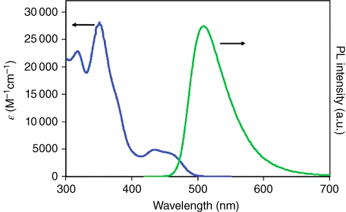
Figure 2.6 (a) Absorption (blue) and emission (green) of 56 in mTHF solution at 295 K. The emission bandwidth is relatively narrow, and the Stokes shift is only 2070 cm−1, the smallest value of any reported Cu(I) complex. Source: Ref. [24]. Reproduced with permission of American Chemical Society.

Figure 2.7 Calculated HOMO (a) and LUMO (b) of 56 at the T1 geometry. For clarity, the alkyl groups have been removed from the visualizations. Source: Ref. [24]. Reproduced with permission of American Chemical Society.
Steffen and coworkers synthesized emissive monomeric and dimeric Cu(I) halogen complexes (42–44 and 45, respectively) containing phen derivatives [91]. TDDFT calculations supported the TADF mechanism, in agreement with the low‐temperature properties of complex 43 in a glassy matrix and of complex 45 in the solid state. However, the temperature dependence of lifetimes for complex 45 suggested that at least two triplet states were involved in the TADF.
Cu(I) complexes with [Cu2(µ‐X)2(N^P)2] structures (52–55) exhibited bright blue‐white luminescence [93]. The triplet state of these complexes had a high radiative rate, with a large zfs value of 10 cm−1. As a result, ∼80% of the emission intensity resulted from the singlet state via TADF, and the remaining 20% was contributed by the triplet state.
Reported dimeric Cu(I) chlorido NHC–picolyl complexes (57–59) possess cuprophilic interactions, with a Cu–Cu distance of 2.52–2.57 Å [94]. Complexes 57 and 58 exhibited TADF with a small ΔEST of 620–740 cm−1. However, complex 59 containing a methoxy group exhibited an unusually short emission lifetime at 77 K and no TADF emission at room temperature, suggesting a ΔEST of >1800 cm−1. DFT calculations indicated that the HOMO was distributed over two copper ions in complex 59 but localized over one copper ion in complexes 57 and 58. The authors noted that relatively small energy splitting between HOMO and HOMO‐1 with different d orbital character greatly enhanced spin–orbit coupling, resulting in a high phosphorescence radiative rate.
2‐Di‐phenylphosphinopyridine (PyrPHOS) is a common ligand used in luminescent Cu(I) complexes. It can be readily modified to change its luminescence color or solubility [96a]. Its straightforward chemical modification and intense solid state luminescence has led to a huge number of dinuclear Cu(I) halide complexes with PyrPHOS‐type ligands being reported by Baumann and Brase [28, 95, 96]. These complexes consisted of a butterfly‐shaped {Cu2(µ‐X)2} core and two substituted PyrPHOS ligands. The small bite angle prohibited mononuclear complexes from forming with these ligands.
Dinuclear Cu(I) halide complexes containing N^P ligands (PyrPHOS‐type ligands) with a diphenylphosphino group consisting of N‐heterocycles have been reported [95]. They exhibited emission from the blue to red regions, with high quantum yields of up to 0.96 in neat powders. The energy separation for complex 60 was experimentally determined to be 400 cm−1. This fact combined with theoretical calculations indicated that the strong luminescence of these dinuclear Cu(I) complexes was due to TADF.
A family of heteroleptic PyrPHOS dinuclear complexes was developed by substituting monodentate ligands in homoleptic PyrPHOS complexes with various P‐donor ligands (60–66) [95–97]. These complexes exhibited very high TADF, with quantum yields of up to 0.99 in neat powders and up to 0.85 in thin films, and were broadly soluble in many solvents, and most were thermally stable at above 250 °C. Heteroleptic Cu(I) complexes tend to undergo dissociation and rearrangement reactions. However, the homoleptic and heteroleptic PyrPHOS Cu(I) dinuclear complexes were sufficiently stable to be used in the solution processing of OLED devices.
In these PyrPHOS dinuclear complexes, the HOMO was largely localized on the metal halide center. The LUMO was mainly located on the bridging N^P ligand. Modifying the N‐heterocycles mainly affected the LUMO energy of the complex. The HOMO energy was largely unchanged, which resulted in a blue shift in the luminescence. Adding different substituents to the PyrPHOS ligands enhanced the solubility in solvents such as toluene. Consequently, the solubility and luminescence color of the PyrPHOS dinuclear complexes could be independently tuned.
In most Cu(I) complexes, radiative processes from the T1 states are not efficient (kr,T ∼ 1 × 10³ s−1). This is because of the large energy separation of the HOMO and HOMO‐1 containing d orbitals. Yersin and coworkers synthesized dinuclear complexes (67–69), in which two Cu(I) ions were bridged by two PyrPHOS ligands [31]. Complex 67 exhibited a large zfs value of 15 cm−1 and a large radiative rate of ∼1 × 10⁴ s−1. This was because of the small energy separation between the HOMO and HOMO‐1 of ∼0.3 eV. Complex 67 exhibited ∼80% of its emission intensity from TADF. The remaining 20% was contributed from phosphorescence from T1. This result hints at the possibility of new strategies for developing TADF‐type Cu(I) emitters with additional radiative pathways.
2.8 Ag(I), Au(I), Pt(0), and Pd(0) Complexes
Other d10 metal complexes such as Ag(I) and Au(I) complexes also reportedly exhibit TADF (Scheme 2.2). Osawa et al. reported that heteroleptic coinage complexes of Ag(I) (70) and Au(I) (71) exhibited bluish green and orange TADF luminescence, with quantum yields of up to 0.32 in the solid state. However, the Au(I) complex was unstable in solution, because of rapid ligand exchange. The Ag(I) complex exhibited low solubility in organic solvents, making it difficult to employ in OLED fabrication [83].
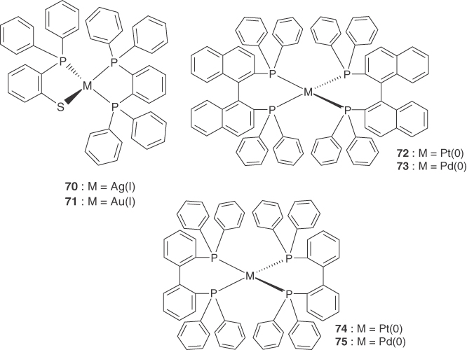
Scheme 2.1Molecular structures of d10 metal complexes.
Pt(0) and Pd(0) complexes (72–75) have been shown to luminesce in solution. Tsubomura et al. reported that the Pt(0) complex, [Pt(binap)2] (binap = 2,2′‐bis(diphenylphosphino)‐1,1′‐binaphthyl), exhibited intense red luminescence, which originated from an MLCT state in benzene [98]. The bidentate binap has an extended π‐electron system with a low‐energy π*‐acceptor orbital. This makes it suitable for MLCT transitions in the visible region.
[Pt(0)(binap)2] (74) exhibited luminescence from an MLCT state. It had a quantum yield of 0.12 and lifetime of 1.2 µs in toluene at ambient temperature. Ultrafast spectroscopic measurements revealed that the intense luminescence was mainly due to TADF and that the lifetime of the prompt fluorescence was 3.2 ps [51]. The large energy difference between the HOMO and HOMO‐2 reduced the extent of mixing between T1 and Sn, due to spin–orbit interactions. This decreased the radiative rate of phosphorescence.
2.9 Summary
This section highlights the TADF properties of d10 metal complexes with various nuclearity (e.g. mononuclear, dinuclear), coordination structures (e.g. three and four coordinate), and ligand type (e.g. X, N^N, P^P, N^P, P^X, etc.). The versatile structures of d10 metal complexes have led to the continuous development of Cu(I) complexes as effective TADF emitters over the last decade. These range from monomeric four‐coordinate [Cu(N^N)2] and [Cu(N^N)(P^P)] to dimeric four‐coordinate {Cu2(µ‐X)2} core, {Cu2(µ‐N)2} core, and N^P bridged {Cu2(µ‐X)2} core, to three‐coordinate [Cu(P^P)X] and [Cu(N^N)X] complexes.
The S1 and T1 states associated with charge transfer involving orthogonal orbitals (i.e. dσ*→ π*) are separated by a very small energy. This leads to some Cu(I) complexes exhibiting efficient TADF with relatively large radiative rate (kr,DF > 2 × 10⁵ s−1). The photophysical data compiled for TADF‐type d10 metal complexes in Table 2.1 indicate that the coordination structure enabling smaller ΔEST is essential to achieve higher kr,DF. Since the ΔEST value reduces with decreasing the special overlap between the HOMO and LUMO of the complexes (see Eq. (2.5)), the uses of appropriate ligands such as dppb, PyrPHOS, and/or dinuclearization are therefore effective strategy to improve the radiative properties of TADF‐type Cu(I) complexes.
The TADF mechanism enables them to harvest both singlet and triplet excitons generated in OLEDs, affording internal quantum efficiencies of ∼100%. The abundance, low cost, and low toxicity of copper makes Cu(I) complexes ideal as emitters in optoelectronics. Moderately strong spin–orbit coupling of the Cu 3d electron enhances the ISC rate from S1 to T1 by up to several picoseconds. This in turn increases the upper limit of the rISC rate and thus the upper limit for the radiative rate of TADF. The spin–orbit coupling also provides an additional radiative channel from the lowest triplet state (kr,T > 3 × 10⁴ s−1).
The major drawback of Cu(I) complexes is their large structural changes that occur in the excited state. This significantly lowers their emission yield and broadens their luminescence spectra because of the large Stokes shift. Some Cu(I) complexes presented herein exhibit more favorable luminescence properties, because this flattening distortion is suppressed by introducing sterically bulky groups on the ligands. Spectral broadening of Cu(I) complexes is detrimental to developing pure color emitters. However, delocalization of the excited state in complexes containing Cu2N2 cores can reduce the luminescence bandwidth and Stokes shift. This may provide an alternative design pathway for the structures of Cu(I) TADF emitters.
Most Cu(I) complexes exhibit low stability due to ligand dissociation or thermal decomposition. This is detrimental for fabricating OLEDs by solution processing or vacuum deposition. However, recently developed Cu(I) complexes are sufficiently stable in solution or at elevated temperature, so are potential emitting materials for low‐cost OLED devices.
References
- 1 DeArmond, M.K. and Carlin, C.M. (1981). Coord. Chem. Rev. 36: 325.
- 2 Lees, A. (1987). J. Chem. Rev. 87: 711.
- 3 Juris, A., Balzani, V., Barigelletti, F., Campagna, S., Belser, P., and von Zelewsky, A. (1988). Coord. Chem. Rev. 84: 85.
- 4 Campagna, S., Puntoriero, F., Nastasi, F., Bergamini, G., and Balzani, V. (2007). Top. Curr. Chem. 280: 117.
- 5 (a) Baldo, M.A., Lamansky, S., Burrows, P.E., Thompson, M.E., and Forrest, S.R. (1999). Appl. Phys. Lett. 75: 4.(b) O'Brien, D.F., Baldo, M.A., Thompson, M.E., and Forrest, S.R. (1999). Appl. Phys. Lett. 74: 442.
- 6 Forrest, S.R. (2000). J. Appl. Phys. 87: 8049.
- 7 Adachi, C., Baldo, M.A., Thompson, M.E., and Forrest, S.R. (2001). J. Appl. Phys. 90: 5048.
- 8 Lamansky, S., Djurovich, P., Murphy, D., Abdel‐Razzaq, F., Lee, H.‐E., Adachi, C., Burrows, P.E., Forrest, S.R., and Thompson, M.E. (2001). J. Am. Chem. Soc. 123: 4304.
- 9 Nazeeruddin, M.K., Humphry‐Baker, R., Berner, D., Rivier, S., Zuppiroli, L., and Grätzel, M. (2003). J. Am. Chem. Soc. 125: 8790.
- 10 (a) Yersin, H. (ed.) (2008). Highly Efficient OLEDs with Phosphorescent Materials. Weinheim: Wiley VCH.(b) Yersin, H., Rausch, A.F., Czerwieniec, R., Hofbeck, T., and Fischer, T. (2011). Coord. Chem. Rev. 255: 2622–2652.
- 11 (a) Baldo, M.A., O'Brien, D.F., You, Y., Shoustikov, A., Sibley, S., Thompson, M.E., and Forrest, S.R. (1998). Nature 395: 151.(b) Baldo, M.A., Thompson, M.E., and Forrest, S.R. (2000). Nature 403: 750.
- 12 Tamayo, A.B., Alleyne, B.D., Djurovich, P.I., Lamansky, S., Tsyba, I., Ho, N.N., Bau, R., and Thompson, M.E. (2003). J. Am. Chem. Soc. 125: 7377.
- 13 Namdas, E.B., Ruseckas, A., Samuel, I.D.W., Lo, S.‐C., and Burn, P.L. (2004). J. Phys. Chem. B 108: 1570.
- 14 D'Andrade, B.W., Holmes, R.J., and Forrest, S.R. (2004). Adv. Mater. 16: 624.
- 15 Sun, Y.R., Giebink, N.C., Kanno, H., Ma, B.W., Thompson, M.E., and Forrest, S.R. (2006). Nature 440: 908.
- 16 Evans, R.C., Douglas, P., and Winscom, C.J. (2006). Coord. Chem. Rev. 250: 2093.
- 17 Armaroli, N., Accorsi, G., Cardinali, F., and Listorti, A. (2007). Top. Curr. Chem. 280: 69.
- 18 Wang, Y., Ding, B., Cheng, P., Liao, D.Z., and Yan, S.P. (2007). Inorg. Chem. 46: 2002.
- 19 Yam, V.W.‐W. and Cheng, E.C.‐C. (2007). Top. Curr. Chem. 281: 269.
- 20 Barbieri, A., Accorsi, G., and Armaroli, N. (2008). Chem. Commun. 19: 2185.
- 21 Zhang, X., Li, B., Chen, Z.H., and Chen, Z.N. (2012). J. Mater. Chem. 22: 11427–11441.
- 22 (a) Tsuge, K., Chishina, Y., Hashiguchi, H., Sasaki, Y., Kato, M., Ishizaka, S., and Kitamura, N. (2013). Chem. Rev. 113: 3686–3733.(b) Tsuge, K., Chishina, Y., Hashiguchi, H., Sasaki, Y., Kato, M., Ishizaka, S., and Kitamura, N. (2016). Coord. Chem. Rev. 306: 636–651.(c) Cariati, E., Lucenti, E., Botta, C., Giovanella, U., Marinotto, D., and Righetto, S. (2016). Coord. Chem. Rev. 306: 566–614.
- 23 (a) Hu, Z., Deibert, B.J., and Li, J. (2014). Chem. Soc. Rev. 43: 5815–5840.(b) Czerwieniec, R., Leitl, M.J., Homeier, H.H.H., and Yersin, H. (2016). Coord. Chem. Rev. 325: 2–28.
- 24 Deaton, J.C., Switalski, S.C., Kondakov, D.Y., Young, R.H., Pawlik, T.D., Giesen, D.J., Harkins, S.B., Miller, A.J.M., Mickenberg, S.F., and Peters, J.C. (2010). J. Am. Chem. Soc. 132: 9499–9508.
- 25 (a) Liu, Z., Qayyum, M.F., Wu, C., Whited, M.T., Djurovich, P.I., Hodgson, K.O., Hedman, B., Solomon, E.I., and Thompson, M.E. (2011). J. Am. Chem. Soc. 133: 3700–3703.(b) Zhang, Q., Komino, T., Huang, S., Matsunami, S., Goushi, K., and Adachi, C. (2012). Adv. Funct. Mater. 22: 2327–2336.
- 26 Zink, D.M., Volz, D., Baumann, T., Mydlak, M., Flügge, H., Friedrichs, J., Nieger, M., and Bräse, S. (2013). Chem. Mater. 25: 4471–4486.
- 27 Tao, Y., Yuan, K., Chen, T., Xu, P., Li, H., Chen, R., Zheng, C., Zhang, L., and Huang, W. (2014). Adv. Mater. 26: 7931–7958.
- 28 Wallesch, M., Volz, D., Zink, D.M., Schepers, U., Nieger, M., Baumann, T., and Bräse, S. (2014). Chem. Eur. J. 20: 6578–6590.
- 29 Xu, H., Chen, R., Sun, Q., Lai, W., Su, Q., Huang, W., and Liu, X. (2014). Chem. Soc. Rev. 43: 3259–3302.
- 30 Czerwieniec, R., Yu, J.‐B., and Yersin, H. (2011). Inorg. Chem. 50: 8293–8301.
- 31 Hofbeck, T., Monkowius, U., and Yersin, H. (2015). J. Am. Chem. Soc. 137: 399–404.
- 32 (a) Smith, C.S., Branham, C.W., Marquardt, B.J., and Mann, K.R. (2010). J. Am. Chem. Soc. 132: 14079–14085.(b) Smith, C.S. and Mann, K.R. (2012). J. Am. Chem. Soc. 134: 8786–8789.
- 33 Liu, X., Sun, W., Zou, L., Xie, Z., Li, X., Lu, C., Wang, L., and Cheng, Y. (2012). Dalton Trans. 41: 1312–1319.
- 34 Sakaki, S., Kuroki, T., and Hamada, T. (2002). J. Chem. Soc., Dalton Trans. 840–842.
- 35 Lavie‐Cambot, A., Cantuel, M., Leydet, Y., Jonusauskas, G., Bassani, D.M., and McClenaghan, N.D. (2008). Coord. Chem. Rev. 252: 2572–2584.
- 36 Bessho, T., Constable, E.C., Graetzel, M., Hernandez Redondo, A., Housecroft, C.E., Kylberg, W., Nazeeruddin, M.K., Neuburger, M., and Schaffner, S. (2008). Chem. Commun. 3717–3719.
- 37 Huang, J., Buyukcakir, O., Mara, M.W., Coskun, A., Dimitrijevic, N.M., Barin, G., Kokhan, O., Stickrath, A.B., Ruppert, R., Tiede, D.M., Stoddart, J.F., Sauvage, J.P., and Chen, L.X. (2012). Angew. Chem., Int. Ed. 51: 12711–12715.
- 38 Sandroni, M., Favereau, L., Planchat, A., Akdas‐Kilig, H., Szuwarski, N., Pellegrin, Y., Blart, E., Le Bozec, H., Boujtita, M., and Odobel, F. (2014). J. Mater. Chem. A 2: 9944–9947.
- 39 Mao, Z., Chao, H.Y., Hui, Z., Che, C.M., Fu, W.F., Cheung, K.K., and Zhu, N. (2003). Chem. Eur. J. 9: 2885–2894.
- 40 Balzani, V. and Campagna, C. (ed.) (2007). Coordination Compounds I. Berlin: Springer.
- 41 Liu, B., Yu, Z.T., Yang, J., Hua, W., Liu, Y.Y., and Ma, J.F. (2011). Inorg. Chem. 50: 8967–8972.
- 42 Yuan, Y.J., Yu, Z.T., Zhang, J.Y., and Zou, Z.G. (2012). Dalton Trans. 41: 9594–9597.
- 43 Wen, T., Zhang, D.X., Liu, J., Lin, R., and Zhang, J. (2013). Chem. Commun. 49: 5660–5662.
- 44 Baralle, A., Fensterbank, L., Goddard, J.P., and Ollivier, C. (2013). Chem. Eur. J. 19: 10809–10813.
- 45 Kjnayzer, R.S., McCusker, C.E., Olaiya, B.S., and Castellano, F.N. (2013). J. Am. Chem. Soc. 135: 14068–14070.
- 46 McCusker, C.E. and Castellano, F.N. (2015). Inorg. Chem. 54: 6035–6042.
- 47 Boudin, S. (1930). J. Chim. Phys. 27: 285.
- 48 (a) Parker, C.A. and Hatchard, C.G. (1961). Trans. Faraday Soc. 57: 1894.(b) C. A. Parker, Advances in Photochemistry, Vol. 2, Ed. by W. A. Noyes, Jr., G. S. Hammond, J. N. Pitts, Jr., John Wiley and Sons, New York, 1964, 305.
- 49 (a) Uoyama, H., Goushi, K., Shizu, K., Nomura, H., and Adachi, C. (2012). Nature 492: 234.(b) Nakagawa, T., Ku, S.‐Y., Wong, K.‐T., and Adachi, C. (2012). Chem. Commun. 48: 9580.
- 50 Siddique, Z.A., Yamamoto, Y., Ohno, T., and Nozaki, K. (2003). Inorg. Chem. 42: 6366–6378.
- 51 Siddique, Z.A., Ohno, T., Nozaki, K., and Tsubomura, T. (2004). Inorg. Chem. 43: 663–673.
- 52 (a) Ceulemans, A. and Vanquickenborne, L.G. (1981). J. Am. Chem. Soc. 103: 2238.(b) Kober, E.M. and Meyer, T.J. (1984). Inorg. Chem. 23: 3877.(c) Miki, H., Shimada, M., Azumi, T., Brozik, J.A., and Crosby, G.A. (1993). J. Phys. Chem. 97: 11175.
- 53 Nozaki, K. (2006). J. Chin. Chem. Soc. 53: 101–113.
- 54 Obara, S., Itabashi, M., Okuda, F., Tamaki, S., Tanabe, Y., Ishii, Y., Nozaki, K., and Haga, M. (2006). Inorg. Chem. 45: 8907–8921.
- 55 (a) Turro, N.J., Ramamurthy, V., and Scaiano, J.C. (2009). Principles of Molecular Photochemistry: An Introduction”, Chapter 4. Sausalito, California: University Science Books.(b) Strickler, S.J. and Berg, R.A. (1962). J. Chem. Phys. 37: 814.
- 56 (a) Siebrand, W. (1970). Chem. Phys. Lett. 6: 192.(b) Lawetz, V., Orlandi, G., and Siebrand, W.J. (1972). Chem. Phys. 56: 4058.
- 57 (a) Buckner, M.T., Matthews, T.G., Lytle, F.E., and McMillin, D.R. (1979). J. Am. Chem. Soc. 101: 5846.(b) Blasse, G. and McMillin, D.R. (1980). Chem. Phys. Lett. 70: 1.(c) Blaskie, M.W. and McMillin, D.R. (1980). Inorg. Chem. 19: 3519.(d) Burke, P.J., McMillin, D.R., and Robinson, W.R. (1980). Inorg. Chem. 19: 1211.
- 58 (a) Kirchhoff, J.R., Gamache, R.E., Blaskie, M.W., Paggio, A.D., Lengel, R.K., and McMillin, D.R. (1983). Inorg. Chem. 22: 2380. (b) McMillin, D.R., Kirchhoff, J.R., and Goodwin, K.V. (1985). Coord. Chem. Rev. 64: 83.
- 59 Everly, R.M. and McMillin, D.R. (1991). J. Phys. Chem. 95: 9071.
- 60 McMillin, D.R. and McNett, K.M. (1998). Chem. Rev. 98: 1201.
- 61 (a) Cunningham, C.T., Cunningham, K.L.H., Michalec, J.F., and McMillin, D.R. (1999). Inorg. Chem. 38: 4388–4392.(b) Cunningham, C.T., Moore, J.J., Cunningham, K.L.H., Fanwick, P.E., and McMillin, D.R. (2000). Inorg. Chem. 39: 3638–3644.
- 62 (a) Chen, L.X., Jennings, G., Liu, T., Gosztola, D.J., Hessler, J.P., Scaltrito, D.V., and Meyer, G.J. (2002). J. Am. Chem. Soc. 124: 10861.(b) Chen, L.X., Shaw, G.B., Novozhilova, I., Liu, T., Jennings, G., Attenkofer, K., Meyer, G.J., and Coppens, P. (2003). J. Am. Chem. Soc. 125: 7022.(c) Shaw, G.B., Grant, C.D., Shirota, H., Castner, E.W., Meyer, G.J., and Chen, L.X. (2007). J. Am. Chem. Soc. 129: 2147.(d) Lockard, J.V., Kabehie, S., Zink, J.I., Smolentsev, G., Soldatov, A., and Chen, L.X. (2010). J. Phys. Chem. B 114: 14521–14527.
- 63 Gunaratne, T., Rodgers, M.A.J., Felder, D., Nierengarten, J.F., Accorsi, G., and Armaroli, N. (2003). Chem. Commun. 3010.
- 64 (a) Iwamura, M., Takeuchi, S., and Tahara, T. (2007). J. Am. Chem. Soc. 129: 5248–5256.(b) Iwamura, M., Watanabe, H., Ishii, K., Takeuchi, S., and Tahara, T. (2011). J. Am. Chem. Soc. 133: 7728–7736.(c) Iwamura, M., Takeuchi, S., and Tahara, T. (2014). Phys. Chem. Chem. Phys. 16: 4143–4154.(d) Hua, L., Iwamura, M., Takeuchi, S., and Tahara, T. (2015). Phys. Chem. Chem. Phys. 17: 2067–2077.(e) Iwamura, M., Takeuchi, S., and Tahara, T. (2015). Acc. Chem. Res. 48: 782–791.
- 65 Garakyaraghi, S., Danilov, E.O., McCusker, C.E., and Castellano, F.N. (2015). J. Phys. Chem. A 119: 3181–3193.
- 66 Mara, M.W., Fransted, K.A., and Chen, L.X. (2015). Coord. Chem. Rev. 282–283: 2–18.
- 67 Iwamura, M., Kobayashi, F., and Nozaki, K. (2016). Chem. Lett. 45: 167–169.
- 68 Sakaki, S., Mizutani, H., and Kase, Y. (1992). Inorg. Chem. 31: 4375.
- 69 Zgierski, M.Z. (2003). J. Chem. Phys. 118: 4045.
- 70 Robertazzi, A., Magistrato, A., de Hoog, P., Carloni, P., and Reedijk, J. (2007). Inorg. Chem. 46: 5873.
- 71 Capano, G., Chergui, M., Rothlisberger, U., Tavernelli, I., and Penfold, T.J. (2014). J. Phys. Chem. A 118: 9861–9869.
- 72 (a) Palmer, C.E.A. and McMillin, D.R. (1987). Inorg. Chem. 26: 3837–3840.(b) Kuang, S., Cuttell, D.G., McMillin, D.R., Fanwick, P.E., and Walton, R.A. (2002). Inorg. Chem. 41: 3313.
- 73 Kaeser, A., Mohankumar, M., Mohanraj, J., Monti, F., Holler, M., Cid, J.‐J., Moudam, O., Nierengarten, I., Karmazin‐Brelot, L., Duhayon, C., Delavaux‐Nicot, B., Armaroli, N., and Nierengarten, J.‐F. (2013). Inorg. Chem. 52: 12140–12151.
- 74 Parker, W.L. and Crosby, G.A. (1989). J. Phys. Chem. 93: 5692.
- 75 Bhasikuttan, A.C., Suzuki, M., Nakashima, S., and Okada, T. (2002). J. Am. Chem. Soc. 124: 8398–8405.
- 76 Cannizzo, A., van Mourik, F., Gawelda, W., Zgrablic, G., Bressler, C., and Chergui, M. (2006). Angew. Chem. 118: 3246–3248.
- 77 (a) Czerwieniec, R., Kowalski, K., and Yersin, H. (2013). Dalton Trans. 42: 9826–9830.(b) Czerwieniec, R. and Yersin, H. (2015). Inorg. Chem. 54: 4322–4327.
- 78 Felder, D., Nierengarten, J.F., Barigelletti, F., Ventura, B., and Armaroli, N. (2001). J. Am. Chem. Soc. 123: 6291.
- 79 (a) Asano, M.S., Tomiduka, K., Sekizawa, K., Yamashita, K., and Sugiura, K. (2010). Chem. Lett. 39: 376–378.(b) McCusker, C.E. and Castellano, F.N. (2013). Inorg. Chem. 52: 8114–8120.
- 80 Chen, X.‐L., Yu, R., Zhang, Q.‐K., Zhou, L.‐J., Wu, X.‐Y., Zhang, Q., and Lu, C.‐Z. (2013). Chem. Mater. 25: 3910–3920.
- 81 Chen, X.‐L., Lin, C.‐S., Wu, X.‐Y., Yu, R., Teng, T., Zhang, Q.‐K., Zhang, Q., Yang, W.‐B., and Lu, C.‐Z. (2015). J. Mater. Chem. C 3: 1187–1195.
- 82 Igawa, S., Hashimoto, M., Kawata, I., Yashima, M., Hoshino, M., and Osawa, M. (2013). J. Mater. Chem. C 1: 542–551.
- 83 Osawa, M., Kawata, I., Ishii, R., Igawa, S., Hashimoto, M., and Hoshino, M. (2013). J. Mater. Chem. C 1: 4375–4383.
- 84 Tsuboyama, A., Kuge, K., Furugori, M., Okada, S., Hoshino, M., and Ueno, K. (2007). Inorg. Chem. 46: 1992–2001.
- 85 Ohara, H., Kobayashi, A., and Kato, M. (2014). Dalton Trans. 43: 17317–17323.
- 86 Zhang, Q., Chen, J., Wu, X.‐Y., Chen, X.‐L., Yu, R., and Lu, C.‐Z. (2015). Dalton Trans. 44: 6706–6710.
- 87 Leitl, M.J., Krylova, V.A., Djurovich, P.I., Thompson, M.E., and Yersin, H. (2014). J. Am. Chem. Soc. 136: 16032–16038.
- 88 Hashimoto, M., Igawa, S., Yashima, M., Kawata, I., Hoshino, M., and Osawa, M. (2011). J. Am. Chem. Soc. 133: 10348–10351.
- 89 Osawa, M., Hoshino, M., Hashimoto, M., Kawata, I., Igawa, S., and Yashima, M. (2015). Dalton Trans. 44: 8369–8378.
- 90 Osawa, M. (2014). Chem. Commun. 50: 1801–1803.
- 91 Nitsch, J., Kleeberg, C., Froehlich, R., and Steffen, A. (2015). Dalton Trans. 44: 6944–6960.
- 92 Kang, L., Chen, J., Teng, T., Chen, X.‐L., Yu, R., and Lu, C.‐Z. (2015). Dalton Trans. 44: 11649–11659.
- 93 Leitl, M.J., Kuchle, F.‐R., Mayer, H.A., Wesemann, L., and Yersin, H. (2013). J. Phys. Chem. A 117: 11823–11836.
- 94 Nitsch, J., Lacemon, F., Lorbach, A., Eichhorn, A., Cisnetti, F., and Steffen, A. (2016). Chem. Commun. 52: 2932–2935.
- 95 Zink, D.M., Bachle, M., Baumann, T., Nieger, M., Kuhn, M., Wang, C., Klopper, W., Monkowius, U., Hofbeck, T., Yersin, H., and Brase, S. (2013). Inorg. Chem. 52: 2292–2305.
- 96 (a) Volz, D., Zink, D.M., Bocksrocker, T., Friedrichs, J., Nieger, M., Baumann, T., Lemmer, U., and Bräse, S. (2013). Chem. Mater. 25: 3414–3426.(b) Volz, D., Wallesch, M., Grage, S.L., Göttlicher, J., Steininger, R., Batchelor, D., Vitova, T., Ulrich, A.S., Heske, C., Weinhardt, L., Baumann, T., and Bräse, S. (2014). Inorg. Chem. 53: 7837–7847.
- 97 Volz, D., Chen, Y., Wallesch, M., Liu, R., Flechon, C., Zink, D.M., Friedrichs, J., Flugge, H., Steininger, R., Gottlicher, J., Heske, C., Weinhardt, L., Brase, S., So, F., and Baumann, T. (2015). Adv. Mater. 27: 2538–2543.
- 98 Tsubomura, T., Ito, Y., Inoue, S., Tanaka, Y., Matsumoto, K., and Tsukuda, T. (2008). Inorg. Chem. 47: 481–486.
- 99 Kober, E.M., Caspar, J.V., Lumpkin, R.S., and Meyer, T.J. (1986). J. Phys. Chem. 90: 3722–3744.
- 100 Gothard, N.A., Mara, M.W., Huang, J., Szarko, J.M., Rolczynski, B., Lockard, J.V., and Chen, K.X. (2012). J. Phys. Chem. A 116: 1984–1992.
- 101 (a) Lotito, K.J. and Peters, J.C. (2010). Chem. Commun. 46: 3690–3692.(b) Krylova, V.A., Djurovich, P.I., Whited, M.T., and Thompson, M.E. (2010). Chem. Commun. 46: 6696–6698.(c) Barakat, K.A., Cundari, T.R., and Omary, M.A. (2003). J. Am. Chem. Soc. 125: 14228.
- 102 (a) Kyle, K.R., Palke, W.E., and Ford, P.C. (1990). Coord. Chem. Rev. 97: 35.(b) Ford, P.C., Cariati, E., and Bourassa, J. (1999). Chem. Rev. 99: 3625.