Industrial Robots
Abstract
This chapter provides more detail on industrial robots commencing with the accepted definition. The various configurations are introduced, including articulated, SCARA, cartesian, and parallel or delta. The typical applications and market shares for each configuration are discussed. The key issues regarding robot performance, including working envelope and repeatability, are discussed together with the main points to consider when selecting robots. This includes a review of the typical contents of a robot data sheet. The benefits that robots can provide are also discussed, both for system integrators and end users. This includes the 10 key benefits that robots can provide for a manufacturing facility.
An industrial robot has been defined by ISO 8373 (International Federation of Robotics, 2013) as:
An automatically controlled, reprogrammable, multipurpose manipulator programmable in three or more axes, which may be either fixed in place or mobile for use in industrial automation applications.
Within this definition, further clarification of these terms is as follows:
• Reprogrammable – motions or auxiliary functions may be changed without physical alterations.
• Multipurpose – capable of adaptation to a different application possibly with physical alterations.
• Axis – an individual motion of one element of the robot structure, which could be either rotary or linear.
In addition to these general-purpose industrial robots, there are a number of dedicated industrial robots that fall outside this definition. These have been developed for applications such as machine tending and printed circuit board assembly and do not meet the definition because they are dedicated to a specific task and are therefore not multipurpose.
As mentioned in Chapter 1, the first application of an industrial robot was at General Motors in 1961. Since that time, robotic technology has developed at a fast pace and the robots in use today are very different to the first machines in terms of performance, capability, and cost. There have been various mechanical designs developed to meet the needs of specific applications, which are described below.
These different configurations have resulted from the ingenuity of the robot designers combined with advances in technology, which have enabled new approaches to machine design. The most significant of these was the introduction of electric drives to replace the use of hydraulics and the increasing performance of the electric drives, providing increased load-carrying capacity combined with high speed and precision.
Initially, hydraulics was used as the primary motive power. Hydraulic power was capable of providing the load-carrying capacity necessary for the early spot welding applications in the automotive industry. However, the responsiveness was poor and the repeatability and path following capabilities limited. For the first installations the robot technicians were required to start work early to turn on the robots, so they were warmed up prior to production starting, to ensure the robots performed repeatably from the first car body to welded.
Pneumatics were used to provide a low cost power source; however, this again could not achieve high repeatability due to the lack of control available. Hydraulics were also used for the early paint robots because electric drives could not, at that time, be used in the explosive atmosphere of the paint booth, caused by the use of solvent-based paints. Painting, by the nature of the application, carrying a spray gun with a 12 inches wide fan, about 12 inches from the surface, did not require the repeatability and control necessary for other applications; therefore, this proved to be a successful application for robots.
Electric drives of various different types have been used. DC servo motors were initially the most prevalent. These however had limited load-carrying capacity, which did initially provide constraints for the use of robots for spot welding applications due to the weight of the welding guns. Stepper motors were also utilised for high precision, low load-carrying applications. Once AC servo motors became available these took over the majority of applications. Their performance has continually increased providing better control, high repeatability, and precision as well as high load-carrying capacity. AC servo motors are now utilised in almost all robot designs.
2.1 Robot Structures
An industrial robot is typically some form of jointed structure of which there are various different configurations. The robot industry has defined classifications for the most common and these are:
• SCARA
• Cartesian
• Parallel (or Delta)
• Cylindrical.
These structures and their benefits are described in more detail below. The structures are achieved by the linking of a number of rotary and/or linear motions or joints. Each of the joints provides motion that collectively can position the robot structure, or robot arm, in a specific position. To provide the ability to position a tool, mounted on the end of the robot, at any place at any angle requires six joints, or six degrees of freedom, commonly known as six axes.
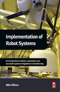
The working envelope is the volume the robot operates within. This is typically shown (see Figure 2.1) as the volume accessible by the centre of the fifth axis. Therefore, anywhere within this working envelope the robot can position a tool at any angle. The working envelope is defined by the structure of the robot arm, the lengths of each element of the arm, and the motion type and range that can be achieved by each joint. The envelope is normally shown as a side view, providing a cross-section of the envelope, produced by the motion of axes 2–6 and a plan view then illustrating how this cross-section develops when the base axis, axis 1, is moved. It should also be noted that the mounting of any tools on the robot will also have an impact on the actual envelope accessible by the robot and tool combined.
The first robot, a Unimate, was designated as a polar-type machine. This design was particularly suited to the hydraulic drive used to power the robot. The robot (Figure 2.2) provided five axes of motion; that is, five joints that could be moved to position the tool carried by the robot in a particular position. These consisted of a base rotation, a rotation at the shoulder, a movement in and out via the arm, and two rotations at the wrist. The provision of only five axes provided limitations in terms of the robot's ability to orientate the tool. However, in the early days, the control technology was unable to meet the needs for six axes machines.

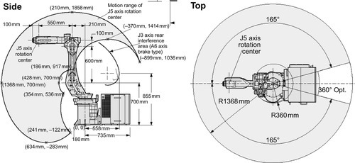
2.1.1 Articulated Arm
The most common configuration is the articulated or jointed arm (Figure 2.3). This closely resembles the human arm and is very flexible. These are normally six axis machines, although some seven axis machines are available, providing redundancy and therefore improving access into awkward spaces. The structure comprises six rotational joints, each mounted on the previous joint. They have the ability to reach a point, within the working envelope, in more than one configuration or position a tool in any orientation at a specific position.
The joint motion of articulated arm robots is complex and therefore can be difficult to visualise. The construction of the arm means each joint has to carry the weight of all the following joints; that is, joint three carries 4, 5, and 6. This impacts both the carrying capacity, the load that can be handled by the robot, as well as the repeatability and accuracy (see Section 2.2). The structures are not particularly rigid and the overall repeatability is the cumulative of all of the axes. However, the increasing performance of AC servo motors and the improvement in the mechanics provide excellent performance for the majority of applications.
As mentioned, the articulated arm is the most common industrial robot structure providing about 60% of annual installations worldwide, although it is higher in Europe and the Americas (International Federation of Robotics, 2013). This type of robot is used for many process applications, including welding and painting, as well as many handling applications including machine tool tending, metal casting, and general material handling. Typical robot sizes range from a reach of 0.5 to over 3.5 m and carrying capacities from 3 to over 1000 kg.
There are also a number of four axis articulated arms. These have been developed specifically for applications such as palletising, packing, and picking where it is not necessary to orientate the tool. Therefore two of the wrist axes are not required. This type of robot is able to achieve higher speeds with higher payloads than the equivalent six axes machines.
Dual arm robots, with two articulated arms mounted on the same structure, are also being developed. These two arms are able to work cooperatively and therefore mimic a human and are aimed at tasks such as assembly where two hands are required to work together to assemble the parts.
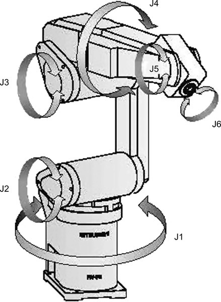
2.1.2 SCARA
The SCARA configuration (Figure 2.4) provides different attributes to the articulated arm. This configuration was originally developed for assembly applications, hence the name Selective Compliance Assembly Robot Arm. The four-axis arm includes a base rotation, a linear vertical motion followed by two rotary motions in the same vertical plane. Due to the nature of the configuration the arm is very rigid in the vertical direction and can also provide compliance in the horizontal plane. It provides high speed combined with high acceleration and works to very tight tolerances.
SCARA machines are typically small with the largest having carrying capacities of about 2 kg and a reach of about 1 m. They are mainly used for assembly applications although they can also be used for packing, small press tending, adhesive dispensing, and other applications. The application of SCARAs is mainly constrained by their size and the limitation of being only four axes.
A standard cycle time test for robots has been defined to provide comparability between machines. This so-called goalpost test consists of a 25 mm vertical move upward, followed by a 300 mm horizontal move, and a 25 mm vertical move down and simulates a typical move for an assembly application. The timings for SCARA robots to achieve this move, both forward and return, can be as low as 0.3 s. This is normally faster than the equivalent articulated arm, six-axis robots.
The SCARA configuration makes up about 12% of global sales although it is more popular in Asia, due to the size of the electronics sector in this region. Asia accounts for about 50% of all SCARA robot sales (International Federation of Robotics, 2013).
2.1.3 Cartesian
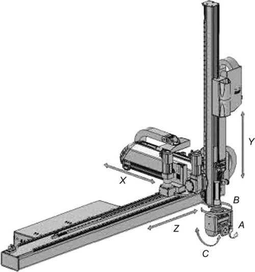
The cartesian category encompasses all industrial robots that include only linear drives for their three major axes (Figure 2.5) and the motions are coincident with a cartesian coordinate system. These machines are often limited to three axes, although some special versions have been developed with additional rotary axes mounted on the last linear axis. This cartesian category includes gantry machines as well as linear pick and place devices. The configuration of these are varied and they can also be constructed from modular kits, providing the flexibility to design a machine for a specific requirement. Gantries can be goalpost type devices, supported on one structure only, as well as area gantries with two support structures. The main axis can range in length from less than 1 m to many tens of metres. Gantries can also be very heavy duty, able to carry 3000 kg. A further benefit of gantries is that they minimise the impact on the factory floor and manual access to machines, as they are largely overhead. However, they are often more expensive than the equivalent articulated arm robots.
Applications are quite varied although they are typically used for handling, palletising, plastic moulding, assembly and machine tending. They also have some application for processes such as welding and glueing, particularly on very large parts. Cartesian machines are the second most popular configuration, taking about 22% of global robot sales (International Federation of Robotics, 2013).
2.1.4 Parallel
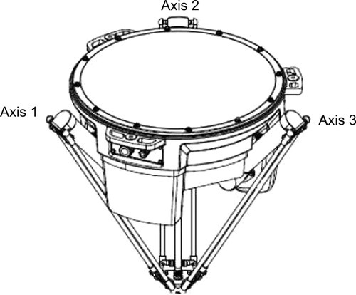
The parallel or delta robot configuration (Figure 2.6) is one of the most recent configuration developments. This includes machines whose arms have concurrent prismatic or rotary joints. These were developed as overhead mounted machines with the motors contained in the base structure driving linked arms below. The benefit of this approach is that it reduces the weight within the arms and therefore provides very high acceleration and speed capability. However they do have a low payload capacity, typically under 8 kg.
Therefore, the main application is picking, particularly on packing lines for the food industry, and also assembly applications. These machines can achieve similar cycle times to the SCARAs with the fastest achieving the goalpost test (25, 300, 25 mm) in 0.3 s. This type of robot is sold in relatively small numbers, achieving only about 1% of the global market (International Federation of Robotics, 2013).
2.1.5 Cylindrical
These robots have a combination of rotary and linear axes, typically with a base rotation followed by a vertical and horizontal linear axis and further rotary axes at the wrist. They provide a rigid structure, with good access into cavities and are easy to programme and visualise. However, they do require clearance at the rear of the arm. They are particularly suited to machine tending and general pick and place applications.
They are mainly used in the electronics industry, particularly clean room applications, and take about 2% of the global market. Similar to the SCARA, they are most popular in Asia, due to the strength of the electronics sector in that region, which takes about 90% of global sales (International Federation of Robotics, 2013).
2.2 Robot Performance
The type of structure and number of axes does have significant implications regarding the performance of a robot, which, as discussed above, does tend to make certain configurations more suitable for specific applications. For example, the SCARA configuration is particularly suited to assembly tasks requiring high speed and repeatability. The robots produced by each manufacturer have different characteristics and capabilities based on the applications for which that particular robot model is targeted. The main robot manufacturers produce a broad range of robots covering the capabilities required to address a range of applications. Originally they specialised in one particular configuration, articulated, SCARA, or cartesian structures and today they still tend to focus on that main configuration, although most do also produce robots with different structures to address the requirements of specific applications. There is often a wide choice of different robots from different manufacturers for any one application.
In addition to the number of axes and the configuration, the main performance characteristics of a robot are defined by the four parameters:
• Repeatability
• Reach and working envelope
• Speed.
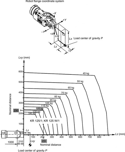
The weight-carrying capacity is normally the maximum load that can be carried at the tool-mounting flange of the robot wrist. With this load the robot will meet all other specifications, including repeatability and speed as well as providing reliable long-term operation. It should be noted that the detailed specifications, often provided in the robot manual, specify the position of the centre of gravity of this load in two directions from the tool-mounting flange (see Figure 2.7). As the distance from the tool-mounting flange increases the available load capacity reduces and, therefore, the ability of a robot to carry a tool or part, even if the weight is below the specified load capacity, may be compromised if the tool is relatively large.
The repeatability as specified for a robot is normally the point repeatability but in some cases path repeatability is also stated. It should be noted that robots, although repeatable, are not inherently accurate. Most robots, because of their structure, are not able to move to a commanded position accurately, for example, an XYZ coordinate in space, but will consistently repeat a taught position, within the tolerance band specified by their repeatability. The point repeatability is useful for spot welding, handling, assembly and similar types of applications but for process applications, such as welding and adhesive dispensing, the path repeatability is more useful.
The reach and working envelope is normally defined to the centre of the wrist axes. For a six-axis robot this is to the centre of axis 5, which means the robot can orientate the wrist to the full capability of its range even at the extreme of the reach or the edge of the defined working envelope. The working envelope is normally shown as a side and plan view (Figure 2.1). The robot should be able to reach any point within the working envelope. It should be noted that the shape of the working envelope will be different for different robot configurations.
The speed is often shown as the maximum speed achievable by each individual axis. This has limited value because the axes do not operate independently and in many applications the moves to be undertaken are often short and do not allow the robot to achieve the maximum speed. However, the actual speed of the robot will influence the cycle time for many applications. The goalpost test (see Section 2.1.2) has been developed, specifically for assembly applications, to provide a reliable speed comparison between different robots.
A further point related to the speed and path repeatability is the tendency of robots to round off corners when moving at high speed. If the robot is programmed to move through a right-angle corner at lower speeds this can be achieved. If the speed is increased, the robot will round off the corner producing an error in the path. This error will increase as the speed increases. Solutions have been developed to address this problem, such as the ABB “TrueMove” control, which ensures the programmed path is achieved irrespective of the speed.
2.3 Robot Selection
The selection of a robot for a particular application is driven by the robot capabilities and performance required to meet the needs of the application as well as the requirements of the solution developed for that application. It should be remembered that there are normally a number of different ways by which the application can be addressed, for example a robot carrying the part to a fixed tool or a robot carrying the tool to a fixed part. Each of these approaches would require different capabilities in the robot. In this case, a different load-carrying capacity may well be required if the robot is carrying the part rather than the tool. The decision as to which route to take may well be driven by other aspects of the proposed system, such as the part handling in and out of the system or the overall cost of the alternative solutions. Therefore the process of robot selection is often iterative, requiring a number of different approaches to be considered before the optimum solution is defined. This is discussed further in Chapter 5.
Once the system concept is defined it is then possible to define the basic capability and performance characteristics required of the robot. These are typically defined by a data sheet, which provides the basic performance and capability information necessary to allow users to select the most appropriate robot for an application. Unfortunately, it is normally not a simple matter of working through the requirements of the application in comparison with the robot specification because a number of the parameters are linked. For example, the robot configuration defines the shape of the working envelope and the robot mounting position then defines how the working envelope is available for use which in turn defines the required reach.
Rarely is there only one parameter that stands out as the most important and therefore forms the starting point. As mentioned above, the normal starting point is a combination of reach, weight capacity, and repeatability. Ultimately the cost and simplicity of the overall solution is normally most important and therefore the robot selection and how it is to be applied should be aimed at achieving this objective (see Chapter 5).
A data sheet would normally cover the main specifications, including:
• Configuration
The robot arm is normally shown as a photograph and/or a schematic that illustrates the type of structure, such as articulated, SCARA, or delta.
• Number of axes
The number of axes is stated or can be determined from other data on the sheet, such as the working ranges and speeds.
• Reach
This is normally stated as well as being illustrated on the working envelope. There may be variants of the model with different reach capabilities shown on the same data sheet.
• Working envelope
Normally illustrated with a diagram showing both side and plan views.
• Payload
The maximum payload on the wrist is normally stated. The data sheet may show variants of the model with different load capacities (different reach variants often have different load capacities). Normally the diagram specifying the payload at different offsets from the wrist (see Figure 2.7) is not included on the data sheet. There is often the capability to add additional load to the robot arm (axes 2 and 3) and this is sometimes, but not always, stated on the data sheet.
• Repeatability both position and path
Point repeatability is normally stated.
• Axes working ranges and speeds
The working range and maximum speed for each axis is normally stated.
• Robot mounting capabilities
If the robot can be positioned in various orientations, such as wall and inverted mounting, this is stated.
• Dimensions and weight
The weight of the robot arm is normally stated and the dimensions of the arm may indicated.
• Protection and environmental capabilities
This would include the IP rating for the standard arm as well as any options. There may also be other options specified such as clean room (for electronics), washdown (for food), or foundry (for hot, dirty applications).
• Electrical requirements
The supply requirements and power usage may be stated.
In addition to the characteristics of the robot arm, the capabilities of the robot controller will be important and these are often defined in a separate data sheet. However, for the initial development of concept solutions, the most important functionality relates to the robot arm. The importance of the controller relates more to the number of axes that can be controlled and the interfacing capability.
2.4 Benefits of Robots
The initial applications of robots were implemented by the early adopters who wanted to test the technology and determine what it might do for their businesses. Decisions to purchase were not necessarily made using stringent return on investment criteria but more on a belief that robot technology showed promise and the purchasers felt it important to be at the cutting edge of the application of that technology.
The increasing use of robots has been driven not by this interest in technology but by much more short-term financial criteria. Most companies today applying robots are basing their investment decisions on financial rewards that can be quantified prior to the investment and also realised once the system is in operation. It should be noted that some but not all of the benefits that can be realised by the use of robots can also be attained by the use of less flexible automation.
The potential benefits that can accrue from the application of robots fall into two categories: those that benefit the end user and those that benefit the automation solution provider. There has been much debate and investigation, largely driven by the robot suppliers, regarding the key benefits from the application of robots. These suppliers obviously have self-interest at heart, but the list of potential benefits has been refined and the International Federation of Robotics published a list of the key 10 benefits in 2005 (International Federation of Robotics, 2005).
These key benefits are as follows:
2. Improve product quality and consistency.
3. Improve quality of work for employees.
4. Increase production output rate.
5. Increase product manufacturing flexibility.
6. Reduce material waste and increase yield.
7. Comply with safety rules and improve workplace health and safety.
8. Reduce labour turnover and difficulty of recruiting workers.
9. Reduce capital costs.
10. Save space in high value manufacturing areas.
It should be stressed that these are potential benefits and may not be applicable in all cases. These are discussed in more detail below. First, the benefits for the automation system provider are discussed.
2.4.1 Benefits to System Integrators
On the presumption that the end user has already been persuaded of the benefits of automation and has decided to consider the purchase of a system, the automation provider or system integrator has the option of basing the solution on robots or other forms of automation. There is an increasing trend within the integrator community to utilise robots at the heart of their solutions. This trend is driven largely by two factors: the flexibility of the robot coupled with the fact that the robot is a standard product.
Robots are standard products and therefore offer measurable and known performance and reliability. As with all standard products, the designs undergo extensive testing prior to release and are also built to published standards. Therefore, a system integrator can review a product catalogue to review the basic specifications, such as load capacity and working envelope, and select a robot that meets the needs of the application (see Chapter 5). The major robot suppliers have an extensive range of robot types and, therefore, there are often a number of alternative machines that can be selected.
These published characteristics allow the system integrator to purchase a machine to meet the needs of its application for a known price. Although it is normally feasible to develop a bespoke machine to achieve the same characteristics, this is more of an unknown in terms of the development time and, therefore, cost. Similarly, the robot being a standard product provides known reliability performance, including mean time between failures (MTBF) and mean time to repair (MTTR), whereas a bespoke machine will always be an unknown quantity. Therefore, the longer-term risk to the end user and, as a consequence, the automation supplier is higher for the bespoke system.
The other major benefit of the robot is the flexibility it provides. The robot comprises multiple axes, often 6 axes, and can therefore orientate parts or tools as required. More importantly the motion of the robot is programmed through software. It is therefore easy to modify the robot operation even at a late stage in the project with limited cost implications. This flexibility can accommodate both late design changes in the product and also mistakes in the design and construction of the automation system.
Both of these factors – the flexibility and the known performance – reduce the risk for the automation solution provider. It is therefore possible to reduce the sales price, as any financial contingency can be reduced, which also increases the likelihood of an order from the end user. Once an order has been received, the timescale of the project may also be reduced, as the delivery of a standard robot may be quicker than the time required to design and build bespoke equipment.
2.4.2 Benefits to End Users
As mentioned above, there are 10 key benefits applicable to end users. In many cases, potential end users only consider the cost benefit of the direct labour saved as a result of the automation but often the financial justification (see Chapter 7) can be improved by also assessing all potential benefits and, in some cases, significant savings from another benefit may outweigh the saving in labour cost. These benefits and their applicability are discussed below.
Reduce Operating Costs
A robot system can help to reduce the operating costs associated with the manufacture of specific parts. This would include direct costs, such as the labour being replaced. However overhead can be also be reduced.
Energy saving can be achieved from a number of sources. The energy per unit of output is optimised by the consistency of the robot and the resulting reduction in scrap or rework. Additionally, robots do not require the same heating (or cooling) and lighting necessary for manual labour. Therefore, if the particular area of the factory can be fully automated it is then possible to reduce energy consumed to maintain the working environment.
The reduction in direct labour may also have an impact on other aspects of the operation, such as training, health and safety, and employee administration. Less indirect labour is required to sustain and manage the smaller workforce and, therefore, savings in overhead costs can be realised.
Improve Product Quality and Consistency
Robots are repeatable. They will consistently produce output that will be of high quality if they are correctly set up and fed consistent input materials. They do not suffer from the inconsistencies of manual labour caused by tiredness, boredom, or distraction that is often associated with tedious or repetitive tasks. This inconsistency results in variable output and variable quality. In contrast, the robot will provide regular output; that is, a known number of manufactured parts per day as well as consistent quality, meaning a known number of good parts per day.
Improve Quality of Work for Employees
Robots can help improve the working conditions for the employees. They can take over dirty, dangerous, and demanding tasks, the so-called 3Ds. Examples of these is paint spraying, working on presses, or handling heavy loads. These are often tasks where it is difficult to maintain consistency, so the application of robots will also improve the production output or the quality of parts produced. The use of robots allows manual labour to be removed from direct involvement in the production process, thereby reducing the pressure on the workers to maintain a regular output.
The operation and maintenance of the robots also requires enhanced skills and, therefore, the motivation of the staff can be improved by enhancing their skills and increasing their pay at the same time as improving their job.
Increase Production Output Rate
As mentioned above, the consistency of robots ensures a regular production output. It also means that the output of other machines can be maximised as the robots will be always be ready to perform their function as and when necessary. For example, machine tools can be unloaded and reloaded exactly when ready rather than waiting for an operator who may be distracted, on a break or involved in some other activity.
It is also possible to run some operations on extended shifts or overnight and on weekends without manual intervention. Again, expensive machine tools can be set up to run overnight using robots to unload and reload, providing additional output for limited additional cost. This enhanced production capability can be particularly valuable for subcontractors who may have variable orders from their customers.
Increase Product Manufacturing Flexibility
Robots are inherently flexible, more so than other forms of automation. Once an operation is programmed into the robot, it can be recalled and be operational within seconds. Therefore changeovers can be very quick, minimising downtime. A robot system can handle variants of the same product or even different products, providing the opportunity for small batch sizes.
There can be constraints caused by the equipment around the robot, such as fixtures or grippers, but by careful design and good concepts these can be overcome. However, it should be recognised that the robot is not as flexible as a human operator.
Reduce Material Waste and Increase Yield
One of the major benefits of robots is their consistency. By ensuring quality output, more “right first time” products are produced and, therefore, material waste is reduced. In addition, the robots will use less consumables to produce the parts; for example, a robot welder will always produce the size of weld required, not too big and not too small. A robot painting system will always apply the same thickness of paint.
The introduction of automation, such as robots, also imposes consistency on the parts or products being fed to the automation, providing an overall benefit to the business. The automation can also be used to check the incoming product and, therefore, identify when product is out of specification. This can be particularly valuable in the food industry where output product must meet minimum weight requirements. Robots and automation can be used to drive down the tolerance band used to ensure the so-called give away, that is the free product provided to the consumer, can be minimised.
Comply with Safety Rules and Improve Workplace Health and Safety
Robots can take over unpleasant, arduous, or health-threatening tasks currently handled by manual workers. There is increasingly stringent health and safety legislation that makes some of these tasks either difficult or impossible to perform manually and robots provide an increasingly cost-effective alternative.
By removing operators from direct contact with machines or potentially hazardous production machinery or processes, robots can decrease the likelihood of accidents. For example, the processing of forgings through foundry presses is both an arduous and dangerous operation that can in most cases be automated by the use of robots. There are many repetitive or intensive industrial activities that can lead to ailments, such as repetitive strain injuries (RSIs) and vibration white finger; for example, the polishing of metal parts or the fettling of castings. The use of robots can remove the operators from these tasks, reducing the risk of injury.
Reduce Labour Turnover and Difficulty of Recruiting Workers
Improving the working environment and also removing the most repetitive or demanding jobs will reduce the labour turnover within a business. The workforce is more likely to be satisfied if it is given more challenging, less repetitive roles that also require higher levels of skill, particularly if these enhanced roles also lead to higher levels of pay.
If staff retention is improved, the cost associated with hiring new workers is reduced. This would include not only the costs directly associated with the hiring process but also training costs and the cost of lower productivity as workers come up to speed on the job.
Reduce Capital Costs
The flexibility provided by robots can reduce capital costs by enabling small batch sizes, reducing the cost of work in progress and inventory. Robots can provide the opportunity to run other machinery more efficiently or perhaps over extended hours, which may mean it is unnecessary to purchase additional machines. For example, one machine tool operated by a robot overnight on a lights-out basis could remove the need to purchase an additional machine tool.
Robot systems, because of their flexibility, are also reconfigurable and can be reused if products or product designs change, whereas more dedicated automation may need to be replaced.
Save Space in High-Value Manufacturing Areas
Robot systems can be very compact as they do not require the same space as an operator performing an equivalent task. Robots can also be mounted in various attitudes, such as wall or overhead, to reduce the space required. This provides the opportunity to minimise the floor space required, which in some cases can be a valuable benefit.
By careful assessment of each of the above benefits, it is often possible to build a case for the application of a robot system with a significantly improved financial return than can be achieved by considering only the labour costs. Further discussion relating to return on investment and the justification of automation is provided in Chapter 7.