Typical Applications
Abstract
This chapter discusses the specific issues that should be considered for each of the main applications for industrial robots. These applications include welding, dispensing (e.g. painting), and processing (e.g. various cutting and material-removal applications), as well as handling operations such as plastic moulding, machine tool tending, palletising, picking, and packing. The discussion starts to bring together items explored in previous chapters, identifying some of the key points relating to each application. This includes the key benefits of using a robot for each these applications, as well as the specific issues that impact robot selection.
This chapter discusses the main issues facing each major robot application. Specifically, we explore the benefits related to each individual application area, as well as the key points to consider when implementing these applications. The engineer must recognise the capabilities of the end user when proposing a solution. More complex solutions increase the capability levels required for users to maintain and operate the system. Therefore, particularly for new users, it is better to keep the system as simple as possible.
4.1 Welding
As previously noted, welding is one of the major areas of robot application, largely due to the benefits that can be obtained from the use of robots for these applications. As a result, significant development work has occurred over a number of years to provide fully integrated and reliable robot welding packages as part of standard solutions. These standard solutions are provided by both the main robot suppliers and the system integrators, and therefore, customers can choose from a large pool of suppliers.
4.1.1 Arc Welding
A typical arc welding system consists of a robot with an integrated welding package providing full control of the welding process (Figure 4.1). The parts to be welded are held in fixtures that maintain the appropriate relationship between the parts while ensuring the weld seams are presented in repeatable positions for accurate weld placement. The fixtures may be mounted in positioners to provide the opportunity to orientate the parts during the welding process, allowing access to the joints to be welded.

An arc welding cell would normally include two stations to allow the robot to weld at one station, whilst the operator unloads and reloads at the other. This arrangement maximises the utilisation of the robot and therefore provides for higher throughput. The two stations may be achieved by the use of a turntable carrying one fixture on each side or, alternatively, two individual stations. More complex systems may include multiple robots, robots on tracks, and multi-axis positioners. If it is not possible to guarantee joint position, touch sensing and through-the-arc seam tracking can be included to allow the robot to find the joints. There are also vision-based weld guidance systems that can be used.
It is important to consider the unloading and reloading operations as much as the robot welding process. In addition to being appropriate for the robot, the fixtures need to be simple for the operator. If at all possible, the fixtures should only allow the parts to be placed in the correct location and orientation. The fixtures must also be quick to load and unload. This ensures that the robot is not waiting for the operator, which would compromise the output. Quick loading and unloading may require the use of automation in the fixtures, such as auto clamping, but there is a cost implication due to the increased sophistication of the fixtures. If the robot cell is to process a number of parts, the repeatable changeover of fixtures may be necessary, and, if required, this functionality must be built into the fixtures. Heavy parts may require the use of cranes or assisted lifting equipment to unload and reload the cell. The design of the cell must also account for this requirement, which may well have implications for the guarding design.
There is a very wide range of potential solutions ranging from the simplest (e.g. a single robot with a turntable) to multirobot systems, including multiaxis positioners and vision tracking. When considering a robot solution, the most important goal is to identify the appropriate solution preferably based on one of the many standard solutions available. As a guide, it is often better to use the simplest solution that will achieve the required weld quality and production throughput.
Users may hope to implement a complex system for processing complete assemblies because this appears to provide the best financial return. This can be difficult to achieve successfully, partly due to the control of the incoming parts but also the capability of the user to successfully operate the system. It is often better to choose a robot welding application with smaller cells producing the subassemblies. This arrangement provides two benefits. First, operating the cells requires a lower-level capability, and therefore, it provides a less challenging learning curve for the engineers and operators. Second, the output is subassemblies that are repeatable, and therefore, when the time comes to introduce the next stage (e.g. the complete assembly), the incoming parts will already be better controlled.
The main benefits of robot arc welding are consistency of performance and increased productivity. The robot places the same weld in the same place every time, using the same welding parameters, which achieves excellent results, as long as the parts and joints are presented consistently. This provides improvements in consistency and quality, reduces rework, and ensures the optimum use of energy and consumables. A typical robot system operates at 85% utilisation or higher, and it performs at this level throughout the full production period. Manual welding normally operates at about 35% utilisation, and it is subject to variation because operators cannot maintain the same level consistently throughout a shift. A typical robot system therefore produces the same output as 2 to 4 welders, dependent on the parts.
For parts such as seat frames, which require a large number of short welds, a robot can be very effective because of the speed at which it moves and reorientates between each of the welds. For larger, heavy parts, such as subassemblies for construction equipment, the speed of the robot is more constrained by the weld process. However, higher-performance processes, such as twin wire welding, can be utilised with robots, allowing the weld speed and thus, the output to be increased.
4.1.2 Spot Welding
Most spot welding robots are located in automotive body shops. These are generally complex, multirobot systems configured in cells or working on transfer lines. The main benefits of robots in these applications are the speed and repeatability of the welding. The robot places the welds exactly as required, both in terms of position and the repeatability of the weld process. Therefore, fewer welds are required to guarantee the integrity of the part being produced.
It is also possible to reduce the sizes of the weld flanges due to the positional repeatability of the robots. Robots are able to handle and orientate larger weld guns than operators, providing the ability to achieve welds that could not otherwise be made and, thus, allowing for greater flexibility in the design of parts. In this way, robots provide for greater flexibility, for a given cost, over other forms of automated welding stations, and, as a result, different models can be processed through the same facility and model design changes can be made with increased frequency.
Probably the most important issue with respect to these robot applications is the dress package providing services to the weld gun. This package must not impede the robot motion or access to the parts to be welded, but it must also be reliable. In addition, the dress package is subject to an arduous operational cycle in terms of the twisting introduced by the robot motion. Therefore, this is the item that is subjected to the most wear during operation, and, as a result, solutions have been developed that are specifically suited to the robot. It is worth noting, the cost of the dress package can be a very significant proportion of the total cost of the welding robot.
The dress package is integrated within the robot arm as far as is possible, with quick disconnect facilities at various points on the robot arm. These points are typically at the robot base, the shoulder of the robot and possibly the robot wrist. The intent is to provide the ability to quickly remove and replace a damaged element of the dress pack without the need to remove the complete package. It is often the case that an automotive body shop will have many different dress packs to suit the different application requirements across the facility. These dress packs are therefore coded so that the correct spare can be quickly identified and correctly fitted to the robot in the event of a failure. Some facilities also calibrate the robots so that, in the event of a robot problem, the complete robot arm can be removed and replaced, without the need for reprogramming, ensuring that production is quickly resumed.
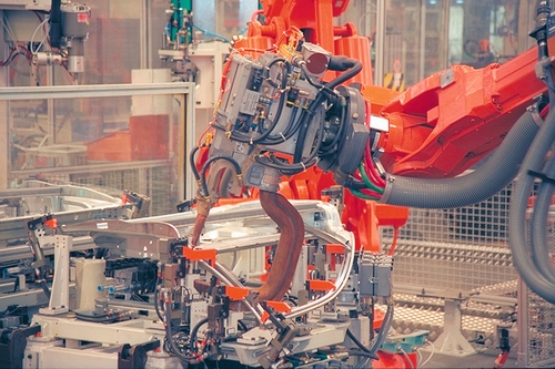
Spot welding robots are also used for automotive component manufacture (Figure 4.2) and for other parts outside of the automotive industry. These tend to be much simpler systems, often with a single robot and a turntable or positioner to present the parts to the robot. The dress packs are normally subject to lower levels of wear in these cases, and therefore, they are less critical. The requirements for the design of the system are very similar to those appropriate for arc welding systems (see Section 4.1.1). The benefit of using robots for these applications is again the speed and consistency of performance, with quality output provided at a rate that is both consistent and higher than can be achieved manually.
4.1.3 Laser Welding
Laser welding is often a costly process due to the equipment required. For many applications, manually performing the operation is not possible, and robots provide a more flexible and dextrous solution than other forms of automation. Two main issues arise with regard to the laser welding application. First, the part presentation is critical. The part fit-up needs to be precise, with minimal gaps between the parts to be welded. Otherwise, the laser process will not operate successfully. This requires the input parts to be highly repeatable with the appropriate fixturing to ensure minimal gaps. Second, the laser must be fed to the robot wrist in a way that does not compromise the robot’s performance but also achieves a reliable laser feed. This is often accomplished via dedicated laser packages designed to suit the specific robot arm. There have also been laser robots developed to provide the feed integrated within the robot arm, but these tend to be very expensive, partly due to the design but also because they are currently produced in low volumes. The other very important issue is safety. Laser applications are housed within a light-tight enclosure to ensure there is no risk to operators and passing personnel. This increases the cost of the guarding package, and it also provides some constraints to the way parts can be fed into and out of the cell.
4.2 Dispensing
Dispensing covers all forms of painting, sealing, and glue applications during which a fluid is output from a dispensing system onto the part to be processed. The robot often carries the dispensing equipment and orientates the applicator around the part to provide the coverage required. There are some cases in which the robot carries the part to a static dispensing gun, normally for adhesive applications, which provides the benefit that the robot can also perform the role of the part-handling equipment, reducing the overall cost of the cell, but this is normally limited to smaller parts.
4.2.1 Painting
Paint applications (Figure 4.3) normally consist of one or more robots painting parts mounted via a hanger on a conveyor to move the parts in front of the robots. The conveyor is often continuously moving because this suits the subsequent flash-off and baking processes. If the conveyor is floor mounted, it removes the risk of dirt and oil falling from the conveyor and hangers onto the painted parts. Larger parts, such as trailers for trucks, may be held stationary in the booth during the painting process, with the robots mounted on tracks to allow them to address all the areas of the parts to be painted. For smaller parts, such as enclosures for electrical items, a simpler part-handling system might be used with an operator unloading and reloading a turntable whilst feeding the painted parts into an oven.

As discussed previously (Section 3.3.2), a painting robot is normally equipped with a process package to provide the various paints and colours to the applicator, which may be a spray gun, an electrostatic gun or an electrostatic bell. The correct definition of the process equipment is a very important element of any paint application, and it is determined by the paint material, the cost benefit of the application method and other items such as the number of colours to be processed and the frequency of colour changes. It is important to consider the gun cleaning and flushing system, which may well impact the resulting paint finish if cleaning is not completed successfully. This is particularly true for two-component (2K) materials for which the mixed material will harden if not removed from the application system. As for other applications, standard packages cover a wide range of materials and application requirements. The most appropriate solution is a balance between the optimum technical solution and the cost of the solutions available.
The main benefit of a painting robot is the consistency of the application. The robot performs the same path with the defined spray parameters, which, subject to the sophistication of the system, can be tailored for different areas of the part. Therefore, the robot achieves a consistent paint film build. This is compared to manual painting that, with an expert, normally achieves the minimum film build but could also exceed this. Less experienced painters are more variable, both over- and underachieving the film build required. On the other hand, the robot solution applies the paint more efficiently, which, subject to the size of the parts, the throughput and the cost of the paint, results in significant financial savings.
This consistency also results in improved quality and a reduction in rework, again providing a financial benefit, and the removal of painters reduces the risk of dirt being introduced into the booth, improving quality and reducing rework. In addition, robots are able to achieve a higher transfer efficiency via better path consistency and control of gun triggering, meaning more of the paint will be on the part and less in the atmosphere of the booth. This not only reduces paint usage, but it also reduces booth cleaning, again saving costs. Robot applications further benefit the working environment in that operators no longer have to wear personal protective equipment (PPE) to work inside the spraying facility, not only saving the cost of the PPE, but also removing workers from this unpleasant environment.
In addition to defining the configuration of the process equipment, the designer must understand the combination of the robot reach, the size of the parts and their location on the hangers, and the time available for painting, which is governed by the speed of the conveyor. This information allows the designer to determine the number of robots needed, as well as the selection of the robot arm with the appropriate reach.
4.2.2 Adhesive and Sealant Dispensing
Sealant and adhesive applications can either use a spray or extrusion application technique (Figure 4.4), with the choice normally being determined by the material characteristics. Spray applications are often used for situations in which a cosmetic finish is not paramount or the location of the parts means the joints will be less precisely located. Extrusion requires the parts to be repeatable and the position of the joint or surface to which the material is to be applied to be positioned repeatably in all three dimensions.
Similar to the above-mentioned process applications, arc welding, and painting, the path repeatability of the dispensing robot provides the main benefit of this application, ensuring the sealant or adhesive is correctly positioned on the part. The systems may well include flow control equipment to ensure the material is dispensed in the appropriate quantity for the part. This can be integrated with the robot to vary the flow rate dependent on the requirements at various points on the part, and it can also adjust the flow rate to match the speed of the robot.
The application may also include conditioning equipment, such as temperature control, to ensure the material is applied at the optimum temperature. 2K materials may be used, and these require an appropriate mixer and also a cleaning system to remove mixed material in the event the system is not used for a period.
Spray systems apply a bead of specific width. The width should be defined to ensure that the joint to be sealed is always covered after taking into account the potential variations in the position of the joint relative to the robot. The designer should account for the geometry of the joints to be processed and the size of the gaps to be filled. For example, it is very difficult to seal an outside corner because the spray tends to push the material to either side of the joint. Similarly, it is not possible to cover holes or fill large gaps because the jet pushes the material through the hole.
Extrusion systems can achieve a constant bead in the appropriate position, provided the part position does not vary. If the stand-off, the height of the nozzle above the part, varies, then the bead may become “wavy”, similar to the problem encountered when icing cakes by hand. In both spray and extrusion, it is better to avoid shaped nozzles if possible. If the orientation of the nozzle is not important, it does not need to be aligned with the joint and therefore rotation is not required at corners which can increase the overall application speed.
In addition to controlling the bead, both in terms of size and position, robots normally perform the application at much higher speeds than is achievable manually. Manually, there is also the risk of “tails” of material from the end of each run, which may require cleaning. Therefore, as well as improvements in quality, the operation time is significantly reduced for a given robotic process verses a manual operation.
4.3 Processing
Process applications include various methods of removing material from the parts being processed. These applications include cutting operations, as well as deburring and polishing operations. Some of the more common robot applications are discussed below.
4.3.1 Mechanical Cutting
Mechanical cutting includes sprue removal from aluminium die cast parts and plastic parts, as well as routing and trimming of plastic parts. In some cases the cutting operation is integrated within the robot machine-tending system. For example, the robot may remove the part from the die cast machine and then orientate the part to a saw to remove the sprue, before placing the completed part on an output station. Provided the cutting operation is completed within the cycle of the die cast machine, the utilisation of the robot is increased, and the cutting operation is achieved for limited additional cost.
Routing operations are normally performed on plastic parts to remove excess material from the moulding operation. This may require trimming around the part and cutting apertures within the part. The positioning of the part is important to ensure the cuts are made as required, and often the fixture matches the shape of the part and includes a vacuum to hold the part down. The selection of the cutting tool must match the material to be cut and the feed rate required.
The main criteria for robot selection are normally the reach required and the weight of the tools to be carried. It is also important to consider the force that may be applied to the robot during the cutting operation, which may require a larger robot to be specified.
4.3.2 Water Jet Cutting
Water jet cutting uses high-pressure water output from a nozzle in the form of a fine jet to provide the cutting force, and, from a robot perspective, this approach has been used very successfully for the trimming of plastic mouldings, as well as the removal of material from apertures. It is also possible to introduce an abrasive material, as a powder, into the water jet for the cutting of tougher materials such as Kevlar. This process provides very a clean cut, without producing dust, at high speeds, and it is therefore a very efficient and clean operation.
The process does produce a water mist within the atmosphere of the booth, however, and the parts must also be dried before passing to subsequent processes. This is often achieved by incorporating a drying chamber into the design of the booth. The process is also noisy and therefore, the requirement for sound attenuation must be included in the design of booth. If an abrasive water jet is used, the jet’s power and cutting capability also make it more dangerous, requiring more substantial booth construction. The effect on the fixtures holding the parts must be considered as well.
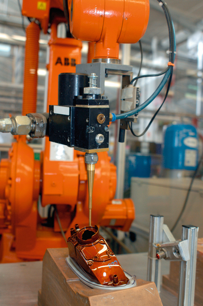
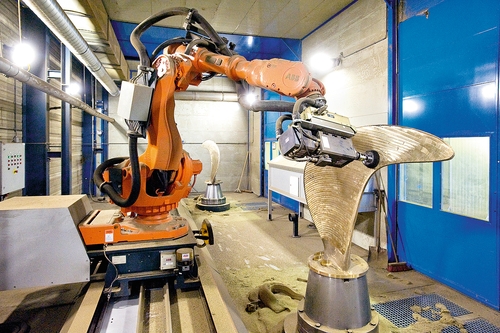
There are two approaches to the process. The first is a fixed water jet head with the robot holding and orientating the part under that head. This has the advantage that the feed of the water jet can be easily achieved to the nozzle. However the gripper needs to be robust, holding the part with enough rigidity to withstand the force of the process. The robot and the gripper may well be more exposed to the process. The second approach is to hold the part in fixtures and carry the water jet nozzle on the robot. This is more of a challenge because the high-pressure water feed can only be carried in metal pipes due to the high pressure. This can reduce the orientation capability of the robot and is normally addressed by using fixed pipes to the shoulder of the robot and then a spiral of pipe wound around the upper arm to provide the feed to the nozzle mounted on the robot wrist (Figure 4.5). This spiral can wind and unwind as the robot wrist orientates and therefore does not impede the motion of the wrist. The robot should be suitably protected from the water mist, which can normally be achieved using an IP67 (see Section 2.3) rated protection to the robot arm, without requiring an additional cover over the robot.
4.3.3 Laser Cutting
Laser cutting is a highly efficient process that can be applied to robots, particularly for parts that require a 3D shape to be cut. The requirements of the application are very similar to those of laser welding (see Section 4.1.3). The process is highly precise, however, in some cases, particularly for small holes, the designer should investigate the robot path performance to ensure it meets the needs of the application.
4.3.4 Grinding and Deburring
Large numbers of robots have been applied to deburring and grinding applications. This is due to the increasingly stringent health and safety standards governing these activities and the need to minimise the risk of operator “white finger” and repetitive strain injuries that often result from these processes.
There are normally two levels of application. The first is a relatively simple material-removal operation, as in the deburring of sharp edges following machining processes. The purpose of the deburring process is to protect personnel performing subsequent operations that require the handling of the parts. The application in this case does not require the achievement of any specific dimensions. Rather it is purely intended to clean the edges. This may be for engine blocks, after machining, to deburr the flash left on the surfaces that have been machined or around holes machined in the block.
A typical application may require a number of different types of tool, including cutters and belts. The robot cell may therefore require a tool change device to allow the robot to pick the relevant tool for the particular feature being deburred. The deburring tool must contact the part with a light pressure and maintain this contact throughout the path. The simplest way to achieve this consistency is often to build compliance into the tool or the mounting of the tool. It is important that the compliance mechanism is designed to ensure that the device performs as desired in all the directions required throughout the operation.
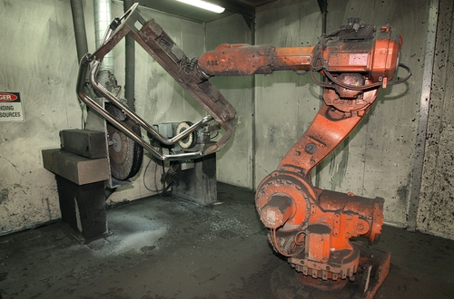
Grinding is more often associated with the removal of metal on a casting to achieve a specific dimension (Figure 4.6). This can also be the case for some deburring applications. The challenge is often caused by the variability in the amount of metal to be removed. Deburring normally requires light removal, and, if the parts are positioned securely and consistently, the robot may move the tool, without compliance, around the part on a predetermined path, and the dimensions required will be achieved. The application does need to respond to tool wear either by the regular changing of tools or a tool-wear checking system.
In most grinding applications, such as those for castings, the material to be removed is more substantial. This normally requires robots that are heavier duty and more rigid than the machines used for deburring applications, and the part holding device, either on the robot or a separate fixture, also needs to be very rigid. One approach is to programme the robot to follow the required path and to utilise a cutting tool with enough power to address the most substantial material to be removed. This has the disadvantage that the robot and cutting tool may be larger than is required for the majority of the process, and the overall speed is also constrained by the slower speed necessary for the large burrs.
As an alternative, force control devices can be incorporated. The force control device can either control the pressure or speed of the application, modifying the robot speed and path as needed to address those occasions when larger burrs are present. This approach ensures the appropriate result is achieved, while maximising the robot speed and also providing the opportunity to utilise smaller robots and cutting tools. However, force control is not a low-cost option, and it does increase the complexity of the system.
4.3.5 Polishing
Robot polishing has been applied to a wide range of components including door furniture, medical implants, and aircraft engine turbine blades. In all cases the finish is important, but in some, such as polishing turbine blades, the dimensions of the parts are equally important. The manual polishing process provides the same health and safety risks as grinding and deburring (see Section 4.3.4). However, polishing often requires the achievement of a surface finish that is much more easily attained by experienced operators and difficult to replicate within a robot system. The operators have the advantage of visual feedback as they perform the task, which currently cannot be replicated within a robot system.
For applications on items such as door furniture and medical implants, the robot often moves the parts between one or more polishing machines (Figure 4.7). There are usually a number of machines, each of which carries belts with various grades of abrasive, or polishing mops. The robot orientates the parts to these belts in turn, commencing with the coarsest and performs a sequence of moves on each grade of belt until the part is finally finished with the polishing mop.
The same approach can also be used with the smaller aero engine blades, although force control may be included to ensure the appropriate force is applied to achieve the required finish. For larger blades, these parts can be mounted in servo-driven positioners to provide orientation of the part in front of the robot. These positioners are the same as those used for arc welding applications (see Section 3.3.1). The robot carries the tool, often with force control included to govern the robot path. If a number of tools are required, then tool changing can also be built into the system.
4.4 Handling and Machine Tending
The largest application area for robots is handling and machine tending. This area covers a very wide range of applications in many different environments, across all different industry sectors from electronics to foundries. Even through the potential applications are broad, all designers must consider some common factors related to robot selection, which are discussed in more detail in Chapter 5. The following section explores some of the issues specific to each of the main applications within this broad area.
4.4.1 Casting
Robots have addressed various operations within casting, including unloading and die spraying for die casting machines, sand core handling and assembly, and metal pouring. The environment in these facilities, particularly in close proximity to the machines, is normally unpleasant and arduous, which provides one of the main motivations for the application of robots. In some cases, such as metal pouring, the operation is dangerous, and in others, such as sand casting, the parts are fragile, and, therefore, the handling needs to be very reliable and performed with care. In this latter case, the repeatability of the robot is very beneficial.
Die casting (Figure 4.8) is used for a wide range of parts with a wide range of sizes. If the parts must be removed from the die and carefully placed, rather than simply ejected, a robot provides a good solution. The robot also provides the benefit of a consistent cycle time, ensuring that the die open time, which affects the cooling of the die, is consistent, thus improving the quality of the parts being produced. The same robot can also be used to spray the die lubricant, again providing consistency of application, ensuring the key areas of the die are addressed and improving quality. Alternatively, if the cycle time of the die is critical, an additional robot can be mounted on top of the die cast machine to perform the lubricant spray operation. It is also possible for one robot to address more than one die cast machine or to perform other operations during the casting cycle, such as sprue removal.

Robots used for die casting and metal pouring applications are normally equipped with higher levels of protection such as IP67, as well as an epoxy paint finish providing corrosion protection and allowing steam cleaning. This protects the robot from the harsh environment. For many die casting applications, the dies eject the part. This can cause a problem because the robot normally resists the force of the ejection. To solve this ejection challenge, a “soft servo” feature allows the servo control to be relaxed at this point. This then means the robot does not resist the force of the ejection, but rather, it moves with it, with the normal servo control being re-engaged once the part has been collected.
4.4.2 Plastic Moulding
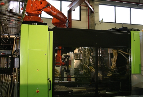
Robots have been used for unloading injection-moulding machines (Figure 4.9) for many years. The products handled include interior and exterior automotive parts, mobile telephone covers, lawnmower parts, even widgets for beer cans. The robot tending of injection-moulding machines provides the benefit of a fixed cycle time, resulting in a fixed tool opening time and consistent die cooling, which, in turn, leads to improved quality. This has also been achieved by more dedicated automation solutions, but these are limited to the unload operation only, and they tend to drop parts to conveyors. Robots can perform secondary operations, as well as unloading, and they are also able to place the parts in the correct orientation on output, minimising the risk of damage.
The grippers tend to be simple, light structures using vacuum cups to grip the part. To ensure efficient operation, the robot must be ready to enter the tool as soon as it starts to open, and the tool must start closing as soon as the robot is clear. This maximises the throughput. Robot reach is often the key parameter, particularly because the parts are often very light. In some cases, when very high throughput is required, the speed of operation may also be important.
Notably, the information provided on data sheets (speeds and accelerations) does not really help because these are theoretical maximums that cannot be achieved in practice. A better test is to simulate the operation to determine the actual cycle time. The robot can be interfaced to the moulding machine, as for other machine-tending applications. In the case of moulding, standards such as Euromap 12 and 67 have been created to provide a predefined interface protocol for injection-moulding machines. A standard solution results, but other interfaces can also be used.
4.4.3 Stamping and Forging
The manual operation of presses is an arduous activity often conducted in a very harsh environment, particularly in foundries. The safety implications for operators interacting with such dangerous machinery also slow the potential output of the presses due to the need to ensure personnel are clear prior to the presses cycling. The use of robots provides benefits not only by improving health and safety but also by increasing the output potential of a press facility.
Stamping operations tend to require the part to be unloaded and a new part reloaded to the press in the minimum time to maximise the output of the press. Press operations normally require more than one press with each press performing a different operation to build to the final shape. The first press receives the blank, normally from a stack, and the output from the final press is often placed in racks for shipping or moving to another area of the factory.
The tools are generally simple frames carrying vacuum cups to grip the part. The frames tend to be quite large because a long reach is often required, and they may be constructed from aluminium sections, but carbon fibre parts have also been used to improve rigidity. These tools are often attached using quick-change facilities for both the mountings and services. This is to assist the tool change that is often required on a frequent basis.
The robots tend to be mounted to one side of the area between the presses. This arrangement provides access for die carts to the presses to allow the dies to be changed quickly. The reach requirement then determines the main criteria for the choice of robot and the size of the gripper frames. The robots can also be interfaced to the presses to minimise the cycle time. This can be achieved by mounting encoders on the press movement. The robot can then be programmed so that it starts to enter the press before the die is fully open, and the die begins closing before the robot has fully removed the gripper and part.
Press forging also requires parts to be moved between presses, although the parts are very hot and can even be over 1000°C. In addition, the environment contains oil mist from the die lubricant spray. The robots therefore require protection from the environment, such as that described in Section 4.4.1. The robots are typically equipped with extended tools to grip the part, while keeping the robot wrist outside the area of the forging press. The grippers also include heat protection, and, in some cases, hydraulically powered grippers may be required to provide the force required to hold the billets.
4.4.4 Machine Tool Tending
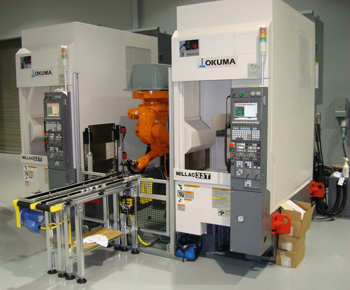
The main benefit of applying robots to machine tools arises from the removal of manual intervention with the machine. Machine tools are already automated, and the only manual operation required is the unloading of the completed part and the loading of the new part to be processed (Figure 4.10). This manual intervention can cause delays to the machining cycle if the operator is not ready to perform the changeover as soon as the machine is finished or does not perform the changeover as quickly as possible. The machine also stops when unattended, as happens during breaks.
Typically, a robot is fitted with a double gripper so it is already holding the new part when it enters the machine. It can then quickly remove the finished part and reload the machine without having to exit the machine. The changeover is therefore accomplished faster than can be achieved manually.
As a result, the automation of the load process does improve the utilisation of the machine, increasing output. It is also possible to provide buffers to allow the robot to continue feeding the machine during breaks and outside of normal production hours. This may lead to a reduction in the number of machines required for a specific production rate, as well as the space required to house those machines. If the machining cycle is lengthy, it may also be possible for the robot to perform secondary operations, such as deburring, during the time available providing additional benefits. Alternatively, if a number of machines are required, either to perform different operations on the same part, or to provide parallel machining activities, the robot may be able to work with multiple machines, increasing the utilisation of the robot and improving the effectiveness of the automation.
One example of a current standard system includes a robot, input and output conveyors, and a vision system. The input conveyor is loaded with parts that do not need to be precisely located. The vision system then identifies the position of the part for the robot, which can then pick the part and load it to the machine tool. Once a part is completed, it is loaded to the output conveyor. As a variation, bins of parts can be loaded into the system with conveyors automatically feeding parts from the bin to the robot. These systems can therefore be loaded with a batch of parts and run unattended for a number of hours.
The savings produced by the automation do not purely result from labour saving. They also result from the increased output from existing machines and, therefore, reduced investment in additional machines. These additional savings can be significant and may form a very important element of any justification.
The selection of a suitable robot is mainly driven by the reach and weight-carrying capacity required. The reach is determined by the size of and access to the machine, as well as the other elements of the system around the robot. Normally, floor-mounted robots are the preferred route, but in some cases, they may be mounted overhead to improve the access. Robots may also be mounted on tracks to provide the opportunity to service multiple machines. Again these tracks can be mounted on gantries, providing the benefit of maintaining a relatively clear floor area and therefore easy manual access to the machines for tooling changeovers and maintenance.
With regard to weight-carrying capacity, the designer must consider the weight of the gripper and the location of the part, when held in the gripper, relative to the wrist of the robot. This offset can be significant and therefore reduces the weight the robot can carry (see Section 2.2). If a double gripper is used, the robot carries two parts for a period within the cycle, and this additional weight must be accounted for.
To provide for an effective system, the designer must also consider issues related to the machine, such as the removal of the swarf resulting from the machining operation, as well as the cutting-tool life and the frequency of tool changeovers. If these are frequent, the operation might benefit from automatic tool changing within the machine tool. If the machine tool is to produce a range of parts, access for tooling changeovers must be considered, in addition to possible gripper changes on the robot and access for maintenance of the machine tool.
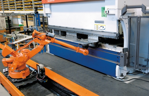
Robots may also be included as an element of the operation for the machine, as happens with pipe-bending machines and press brakes (Figure 4.11). In these cases, the robot provides orientation of the part between operations to ensure the correct changes in form are achieved. These systems provide similar benefits to machine tool-tending applications, particularly relating to increased productivity, part repeatability and reduced health and safety issues.
4.4.5 Measurement, Inspection, and Testing
Robots are used for many inspection applications. The main benefit is the ability to move the measurement devices, such as vision systems, to a number of different points to inspect or measure different parts of the product to be tested. Robots have also been applied to mechanical test rigs to provide motion as an alternative to bespoke motion systems. In both cases, the benefit of using a robot is the reduction in cost of the overall system. In the former case, a smaller number of measurement devices are required and in the latter the cost of the robot may be lower than the cost of designing and manufacturing the bespoke system.
One key issue when considering the use of robots is to remember that these machines are not accurate, and, therefore, the designer must compensate for their inherent inaccuracy. If absolute measurements are being made, then appropriate compensation or reference measurements must also be made. In addition, it may be necessary to include temperature compensation to account for physical changes to the robot due to changes in the environment.
4.4.6 Palletising
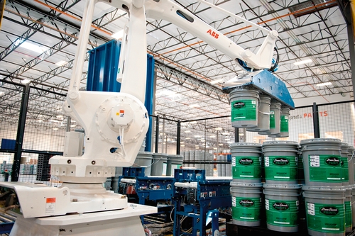
Palletising is a major robot application due to the speed of operation and flexibility a robot can offer, as well as the reliability provided by a robot system. A robot system provides benefits, in comparison with manual operations, based on labour saving, increased speed of operation and also improved health and safety, by the removal of lifting activities. In comparison with more dedicated palletising machines, a robot provides increased flexibility and, in some cases, particularly for light packages, improved palletising reliability. The increased flexibility lets the operation palletise different packages to different pallets, even if they arrive on the same line, reducing the time lost due to pallet changeovers.
Normally, a four-axis robot is used for palletising applications because it is not necessary to change the orientation of the package (Figure 4.12). The choice of robot is largely based on weight capacity and reach, and the designer determines it based partly on the product to be palletised and the layout. The required cycle time may also influence the design if it is necessary to pick multiple packages or even complete layers for each cycle. Section 5.2.3 further discusses the selection of the robot in relation to concept development.
The gripping method is an important element of the system. In many cases, a pneumatic solution is both viable and generally preferred due to simplicity, speed of operation, gripper weight, and cost. This can be achieved via an array of individual pneumatic cups or, alternatively, a Unigripper-type approach. The Unigripper normally provides more flexibility than a simple array of vacuum cups. For sacks, particularly of powders and loose materials, a clam shell-type gripper is often used (see Section 3.4). These are very effective for this type of product, but they are slower than vacuum grippers. It is also possible to use mechanical grippers, such as fork lift-type devices or even plates, to grip the part. These place constraints on the way a stack can be built on the pallet, because they do require access on the sides of the package and, therefore, are slower than a vacuum device. Their use needs to be carefully considered to ensure they do not damage the package, but, in some cases, they are the optimum approach.
4.4.7 Packing and Picking
The benefits of applying robots to packing and picking applications are often throughput; labour saving, particularly for multishift operations; and consistency leading to improved quality. Vision systems are often required to identify the location of the products to be picked, and, as a secondary feature, they can provide quality control. In some cases, particularly where the products are heavy, there are also health and safety benefits.
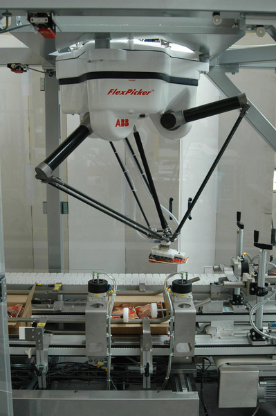
If very high speed is required and the products are light, the system might benefit most from inverted delta-type robots (Figure 4.13), such as the FlexPicker (see Section 2.1.4). These are specifically designed for this type of application, and although they are generally four-axis machines, this axis arrangement provides the motion required for most picking and packing applications. In some applications, particularly secondary packing applications during which the products are placed into boxes or cartons, six-axis robots might be more effective because they provide additional orientation capabilities. Articulated robots are also a better configuration for reaching into boxes.
For many primary packing applications, the gripping technique is the challenge, and the weight of the gripper may well be higher than the weight of the product. Therefore, the choice of robot cannot be determined until the basic design of the gripper is known. Also, these primary packing applications are often performed in high care areas of food factories where hygiene is critical, and the robots must meet the relevant standards, as well as being designed for washdown cleaning (see Section 2.3).
4.5 Assembly
Assembly is a growing application area, with the electronics industry being a major user, especially in the area of consumer electronic products. A typical robot assembly system is shown in Figure 4.14. Robots provide precision, speed, and consistency that are not achievable manually, as well as flexibility that cannot be provided by more dedicated assembly systems. Typically SCARA robots (see Section 2.1.2) have been used for assembly, but six-axis and delta robots are increasingly employed in this application. Delta robots can achieve high speed, but they have a limited working envelope and must be mounted above the area in which they are to operate. SCARA robots are also fast, and, like deltas, they are limited to four axes, but they can provide a very effective working area. SCARA machines tend to be lower cost than both the equivalent delta and six-axis machines. The main benefit of six-axis machines is their flexibility, which provides additional orientation capability and reduces the risk in the assembly system design.

The most important parameter for most assembly applications is speed, particularly for electronics assembly. Specifications for robots in assembly applications include the standard goal post test (see Section 2.1.2). This gives a time for standard type of assembly move up, across and down, and, therefore, it provides a way of comparing different robots and configurations for this particular move. Payload can be important and must account for the weight of the gripper mounted on the robot. Reach and size may also be important, often because the assembly systems need to be compact. As a result, a compact robot may be better suited than a larger machine.
In addition to the above parameters, mechanical assembly applications may require a force to press two parts together. In this case, the ability of the robot to apply that force may be important. This type of information is not normally apparent from the standard data sheets, and it may require a more-detailed discussion with the suppliers. Assembly systems may also include joining functions, using additional fixings such as screws or bolts. It is possible to automate many of these operations, but some are much easier than others. The design of the product and the fixing method also significantly impacts the ease of automation and the reliability of the final solution.
One of the most important issues for assembly applications is positional repeatability. If two parts are to be joined by some mechanical method, the parts must be located within tolerances that allow the joining technique to operate. This may require some form of lead in or chamfer on the parts. It may require vision to identify part locations. It is necessary for the parts themselves to be repeatable. For example, if components are to be inserted to a printed circuit board, the legs on the components must be straight and undamaged. One of the other major challenges for assembly is the feeding of components (see Section 3.1.3). The use of bowl feeders and other mechanisms to reliably feed the parts to the assembly system is key element of the success of the system.