Automation System Components
Abstract
An automation system will include different components, in addition to the robot, to provide the complete solution. This chapter provides an introduction to some of the most frequently used technologies, including handling and feeding systems, vision, grippers and tool changers, as well as tooling and fixtures. The process equipment required for a robot application is discussed, particularly for welding, painting, dispensing, and material removal applications. Assembly automation is also reviewed. The basic requirements for the system control, including networks and human machine interfaces, are introduced together with the basic principles of safety and guarding for automation systems.
Each automation system is configured to meet the specific requirements of the application for which it is intended. As will be seen in Chapter 4, there are many different types of automation systems for a wide range of applications across almost all manufacturing sectors. The application requirements for automation in the food industry are very different to the requirements for the electronics sector. Therefore, there can be many different automation components that need to be brought together to successfully address the requirements for a specific application. These components also vary significantly between each application; for example, a gripper for picking soft fruit is very different from a gripper for handling hot forgings.
It is not possible to provide an exhaustive appraisal of all the various types of automation components due to the wide range and varied specifications and capabilities this would cover. However, the main components can be reviewed and the most important features of each of these discussed. The intention is to provide an overview of the more common elements of automation systems and also the most important issues that should be considered when using these components.
This chapter covers the following:
• Vision systems
• Process equipment
• Grippers and tool changers
• Tooling and fixturing
• Assembly automation components
• System controls
• Safety and guarding.
The development of an automation system, by the integration of these automation components together with robots, is discussed further in Chapters 4 and 5.
3.1 Handling Equipment
In any manufacturing facility it is critical that materials be delivered to the various operations as required for the efficient processing of the parts through that facility. The objectives for any material handling operation are getting the right parts to the right place, at the right time, in the right quantity, and also avoiding damage to these parts. The consequences of a poorly designed or inappropriate material handling system include: excess work in progress, disorganised storage and poor inventory control, excessive handling, product damage or excessive scrap and idle machines. It should always be noted that material handling does not add value to the product, it only adds to the cost. Therefore, the material handling needs to be as efficient as possible to minimise this cost.
There are many different types of equipment used, including pallet trucks, forklift trucks, overhead cranes, and conveyors, to provide for mass movement of parts around a facility. These are not considered in detail here. The objective of this section is to review those handling systems that can have a direct impact on the design and operation of an automation system. With any automation system, the feeding of parts to the system and the removal of completed parts can, if the handling is not appropriate, seriously affect the performance of the automation system. Therefore, the handling systems must always be considered when automation solutions are being developed to ensure the planned performance is not constrained by the input or output of the parts. Automation will not solve material handling issues. Conversely, automation will often highlight any material handling problems because the automation system will not perform as intended.
3.1.1 Conveyors
Conveyor systems can be used to move parts between automation systems and also within a single automation system; for example, the feeding of boxes from packing lines to robotic palletising systems or the transfer of parts within an assembly system. Conveyors provide for fixed movement between two points along a predetermined path. They can be on the floor, located above the floor or positioned overhead. The selection depends on the product to be moved, the space available, and the access required to the other equipment and operations. They are particularly suited to moving high volumes of product and can also provide temporary storage or buffers between specific operations.
The motion of conveyors is normally either continuous or indexing. Continuous conveyors do not stop, and the processes need to be performed on the moving line or the products need to be removed for specific operations to take place. Indexing conveyors are often used within assembly-type operations where the product will be stopped for each operation to be performed; however, these provide a constraint as the conveyor can only move when the slowest operation has been completed. An automated system may include a small number of conveyors; for example, to provide for the automatic removal of full pallets from a palletising system, or a number of different conveyors of different types and speeds to provide for the flow of parts or products through a complete system. Often, the conveying solution is determined by other operations. For example, a continuous conveyor is very efficient for a painting operation because the product can be reliably fed through the oven, via a continuous conveyor, to achieve a repeatable and efficient baking cycle.
There are many different types of conveyors including belt, chain, and roller conveyors. Belt conveyors are particularly suited to the movement of low weight and delicate items, such as food products. They are also more suited to applications where cleanliness is important, such as the food sector, but are limited to straight lines. Chain conveyors either carry the product direct on the chain or via carriers that are linked to the chain. These are suited to heavier products and slower speed applications, such as the transfer of pallets or the conveying of parts on fixtures through a paint shop. Roller conveyors are particularly suited to midrange parts in terms of size and weight, such as cartons, and are often used to feed packed product to palletising or storage systems.
3.1.2 Discrete Vehicles
Automated guided vehicles (AGVs) can achieve some of the benefits of conveyors but provide greater flexibility and less obstruction on the factory floor. However, they cannot handle the same throughput as a conveyor, do not inherently provide a buffer and are more expensive. An AGV is effectively an unmanned vehicle that is guided automatically around the factory floor. This can be achieved by a buried wire, which the vehicle can sense and follow.
It is feasible to provide different routes and junctions that can be selected by the overall control system to allow the AGV to deliver products via different routes to multiple operations. The AGVs often operate in the same working area as other users, such as forklift trucks and the workforce; therefore, they include appropriate safety systems. AGVs are, however, relatively slow and are limited in terms of the size and weight of product that can be handled. Because they are guided by wires buried in the floor it can be expensive to change or expand an AGV system. Self-guided vehicles are also available that use wall-mounted targets and laser scanners or an internal GPS system to determine their location. These self-guided vehicle systems are less constrained, simpler to modify and, therefore, provide greater long-term flexibility.
3.1.3 Part Feeding Equipment
In all automation systems, there is a need to feed individual parts into the system. The most effective approach may be the manual loading of parts into fixtures (see Section 3.5); for example, the loading of sheet metal components into a fixture for a robotic welding system. Alternatively, the feed may be via a conveyor system bringing the parts from a previous operation. For some applications, particularly assembly, there is the need to feed individual components, in high volumes with high frequency, into the automation system.
The components being fed could either be parts to be assembled or the joining tool, such as screws or rivets. These feed systems must be highly reliable because the effectiveness of the automation system is totally dependent on the performance of the feed systems. The feeding system, in addition to providing the components to specific positions for subsequent operations, also needs to ensure the parts are orientated correctly for these operations. There are a number of techniques, including magazine and bandolier feeders (see below), which can be used but these require preprocessing to pack the components and provide the orientation prior to loading to the feeders. However, many components are delivered loosely in boxes or crates. The cost of the parts may be lower because no preprocessing is required but the automation system needs a mechanism to accept these parts in bulk and in random orientations, which can then sort the components and deliver them to the required positions in the desired orientation. The vibratory bowl feeder is the most common equipment used for this purpose with almost 80% of feeding to automated assembly systems being achieved using bowl feeders.
The design of the parts can have a significant impact on the ease with which they can be fed, which in turn drives the cost of the feeding system. If parts can be symmetrical, it minimises the sorting required. If some features are nonsymmetric, then it helps if this applies to the major features so, for example, the centre of gravity can be used to sort the parts. If open hooks are included there is a risk of tangling, whereas closed hooks will ensure tangling is not possible. It is therefore important that part design also considers the methods by which the parts are to be fed and processed by an automation system.
Bowl Feeders
Vibratory bowl feeders (Figure 3.1) consist of a bowl that is vibrated via an electromagnet. Within the bowl, a spiral track rises from the centre of the bowl around the inside of the periphery to the top. The vibration causes components within the bowl to rise up the track and, therefore, be fed out of the bowl. Towards the top of the track a selector mechanism, consisting of various mechanical features such as pressure breaks, wiper blades, and slots, is used to sort the components to ensure only those in the correct orientation are fed out of the bowl. Those that are incorrectly oriented drop back into the bowl to be recycled.
The size of the bowl is mainly dependent on the size of the components to be processed. Bowls can either be replenished manually or can be fed via external elevators taking product from a bulk hopper and depositing it into the bowl. The indexing of the elevator, providing a new quantity of product, is controlled to ensure the bowl always contains an appropriate number of parts.
Bowl feeders are simple devices and are highly reliable. They are by far the most frequently applied feed system and do provide sorting of parts from a random feed. Parts can be literally tipped into the bowl, and can handle a wide range of items, generally from small to medium size. The initial design of the bowl is critical both for the correct operation and the sorting. The gradient of the spiral track needs to be correct to ensure the parts rise up the track correctly, and the design of the selector mechanism needs to provide the required sorting. The design is based on the inherent characteristics of the components, including geometry and centre of gravity. The design is more an art than a science and is largely based on experience. The two main limitations of bowl feeders are they cannot handle parts that can be damaged by contact with other parts and also parts that can tangle, such as springs.
Linear Feeders
Linear feeders work in a similar way in that vibration provides the motion; although in this case in a straight line rather than the spiral of the bowl. These are often used in conjunction with a bowl feeder, taking the parts output from the bowl and feeding them to the required position within the automation system. Linear feeders can also feed larger parts, or more delicate parts, than can be fed via a bowl feeder; however, they do not provide any sorting, so the parts must be oriented correctly by another device, normally before the linear feeder. Alternatively, an intelligent picking system, possibly using vision (see Section 3.2), can determine the part position and orientation to provide for picking from the feeder.
Blow Feeders
Basically the part is blown down a tube that provides for fast delivery of parts but is limited to small parts. The use of the tube also provides the opportunity to feed components over a relatively complex or variable path; for example, to the end of a moving multiaxis device, such as a robot. This technique is typically used to feed screws or rivets to the application device, which could be mounted on a multiaxis mechanism to position it at locations on the component where the fixing is required.
Bandoleer Feeders
The components are held in bandoliers or tapes, which are then loaded to the automated machines. This technique is mostly used by the electronics industry to feed components to printed circuit board assembly machines. The bandoliers have to be premade, but the components are usually produced on automated systems that can relatively easily provide their output on bandoliers.
Magazine Feeders
Magazine feeders require parts to be prepacked either into trays or dispensers. Trays are suitable for parts that can be damaged by other feeding techniques or parts where the correct orientation is difficult to obtain. The trays can be moulded and are therefore low cost. It is often possible to use these trays to provide transport between manufacturing operations, normally stacked on pallets, providing for ease of transport and protection for the parts. The unloading of the tray into the automation system does require some form of handling device, which may be a robot or simple manipulator, to pick each part, or groups of parts, from the tray and place the part or parts into the required positions within the automation system.
Dispensers are often used in packing systems. These may be to feed card to case erectors producing boxes for the packing system or plastic trays, which are then being filled with the product. This might be the plastic packaging used for many food products. Dispensers are normally simple devices that hold a stack with a simple arm removing single items, picking using a vacuum gripper. These items are normally placed on a feed conveyor to provide transport into the packing automation.
3.2 Vision Systems
Machine vision is basically the use of optical, noncontact sensors to automatically receive and interpret an image of a real scene to obtain information and/or control machines or processes. Vision systems can be used in isolation, for example, as an inspection tool, or within an automation system. Initially vision systems, like most automation equipment, were expensive and difficult to implement and use. In recent years the cost has reduced significantly, vision capability has increased enormously, and they are now much easier to use. Therefore, the use of vision has grown exponentially and vision is now a widely used tool within many automated systems and processes.
It should be noted that machine vision in many respects does not yet match the capability of human vision and, therefore, careful consideration must be given to any vision application. Machine vision is consistent and tireless, may operate outside the visible light spectrum, can work in hostile environments, and precisely follows a predefined programme. Human vision, by contrast, has a much higher image resolution, can interpret complex scenes very quickly, is highly adaptable but is constrained to the visible light spectrum, does tire, and can be subjective.
Machine vision is suited for part identification, finding positions, inspection, and measurement. It is therefore used for applications such as inspection on high-speed production lines, microscopic inspection, closed loop process control in all environments including clean rooms and hazardous environments, as well as precise noncontact measurement and robot guidance. It is not intended to cover all these applications here but to focus on issues related to the use of vision within robot systems. The main applications of vision within robot systems are guidance, both for part picking and tracking, part presence/absence checking, defect identification and part identification, including optical character recognition and barcode reading. These will be discussed in more detail later.
First, it is worthwhile to briefly identify the main elements of a vision system and how it operates. A typical vision system would include the camera, lighting, processing hardware and software. The software is configured to tailor the vision system and the analysis performed to the specific application. There are three main operations within a vision system. The first is to obtain the image; second, to process or modify the image data; and finally to extract the desired information. Each of these operations has an impact on that which follows; for example, the method of lighting in the first operation can greatly simplify capturing the image, which then reduces the processing required and makes it easier to extract the desired information.
There is a wide range of cameras available, with the key parameters being resolution, field of view, depth of field, and focal length. The focal length determines the nominal distance at which the camera will provide a focused image, and the depth of field describes the range over which this focus is maintained. The field of view determines the size of the image taken at the focal length, and the resolution is the number of individual steps the image is divided into, which then determines the smallest measurement or feature that can be identified.
Lighting is most important. There are a number of different techniques available, including both direct and diffused lighting from the front, back, or side of the object as well as structured and polarised lighting. The effect of ambient lighting including: sunlight, general factory lighting, and light from any other sources must be considered. In particular, the impact of changes in ambient light must not affect the operation of the vision system. The purpose of the vision system lighting is twofold: first, to highlight the important features of the object and second, to remove any potential impact from changes in ambient light.
As an example, for weld guidance systems the vision sensor is mounted directly in front of the welding torch, looking at the weld seam only about 25 mm in front of the weld. To allow the camera to “see” the weld seam, the illumination is provided by a infrared laser-generated line and a filter is mounted in front of the camera to remove all the light with the exception of the wavelength of the laser. The light from the welding process is therefore removed from the image received by the camera, which then allows the camera to “see” the weld seam.
Back lighting can be very helpful for part location and measurement because it reduces the image of the object to a shadow, removing any features on the surface and, therefore, simplifying the task for the vision system. The background on which the object sits can also be important to help differentiate the part. A typical application for vision is to provide part location and orientation information when robotically picking parts from conveyors; for example, the packing of chocolates into boxes. White conveyors are often used because these provide a strong contrast between the colour of the chocolates and the conveyor.
The processing complexity and time required can be significantly reduced by highlighting the important features or removing unnecessary information from the image. Additionally, the reliability of the vision operation is also improved. The reliability is also improved if the effect of changes in ambient light can be removed. To fully remove the effect of ambient light it may be necessary to enclose the vision operation within a light-tight box.
Within robot automation systems, one of the most popular uses of vision is within packing applications, particularly within the food industry. Products are normally randomly positioned on conveyors being fed into a robot packing cell. The vision system is used to identify the positions of the products and feed the information to the robots to allow them to pick the product from the conveyor and place it into the packaging. These are normally moving conveyors and, therefore, the positions as measured by the vision system at the input need to be tracked through the cell to the picking point. These systems normally include multiple robots, so there is also an assessment made of which robot should perform the picking operation to balance the workload between the robots. There are standard solutions available for these types of applications, which have made their implementation much simpler and cost-effective.
The same vision system can also provide quality control; for example, by checking the shapes of the chocolates to be packed to ensure any misshapes are discarded. A further example is the packing of small pancakes where the vision also checks the colour of the pancake. Too dark indicates the pancake is overbaked or too light that it is underbaked; in both cases, the pancake is discarded. Vision is also used, particularly within assembly systems for the checking of features or parts within an assembly. This provides a check that a prior operation has been performed successfully and ensures an assembly does not continue with incorrect parts.
Vision has also been used to check that a fixture manually loaded with a number of different parts has all the parts loaded prior to the next operation to ensure everything is in place as required. This could be achieved with individual sensors for each part but the vision approach may be more cost-effective, particularly if there are a number of different variants processed through the same fixture.
Vision can be used to read characters on labels or barcodes to provide for product identification. For example, a palletising system may be receiving a mix of boxes with the vision system identifying the box to ensure it is placed on the correct pallet. In most applications of this type, a barcode reader would normally cost less but there are situations where a vision system is the more appropriate solution.
Machine vision by providing guidance, measurement, or quality control therefore enables the automation of applications that would not be otherwise feasible. The cost of vision systems continues to decrease and their ease of use and performance continues to improve. However, they do require careful investigation to ensure reliable operation.
3.3 Process Equipment
Automation systems can be divided into two categories: those which handle parts for assembly, machine tending, or general material handling and those which apply some form of process. The former category tends to use grippers mounted on the robot, whereas the latter require some form of process equipment to control and apply the process. These process applications include:
• Painting.
• Dispensing of adhesives or sealants.
• Cutting and material removal.
Most of these processes can be accomplished manually, and the initial robot applications basically utilised the manual equipment mounted to the robot arm to replicate the manual application. However, over time the process equipment has been developed to suit the automated applications and techniques, and equipment has been developed that is more suited to the automated application. This has resulted in systems that are more closely integrated with robots, both mechanically and within the controls, to provide more effective, robust, and reliable solutions. It is not intended to provide a complete study of all the processes but to cover the most important issues related to the application of robots to these processes, as discussed below.
3.3.1 Welding
The main types of welding processes are spot welding and arc welding. Arc welding covers a number of process variants such as metal inert gas (MIG) and tungsten inert gas (TIG).
Spot Welding
Spot welding joins two sheets of metal together by applying a force to close the gap between the sheets and then passing an electrical current through the contact point causing fusion of the metal at the contact point. It is used extensively in the production of car bodies. The spot weld gun consists of two arms, each of which carry contact tips. The arms are driven, typically via pneumatics, to close the contact tips on the metal sheet providing the force to close the gap between the sheets. A transformer provides the electrical current, which passes through the circuit made by the arms and contact tips, generating the heat at the point of contact and thereby causing fusion. The key parameters controlling the process are the current supplied and the length of time it is applied.
The size and design of the arms of the welding gun is determined by the part to be welded. The contact tips need to be placed on each side of the flange to be welded and, therefore, the guns can often be large and unwieldy. This makes them difficult to orientate to the correct position manually; whereas robots can handle the weight and achieve the positioning required both quickly and accurately. As a result, spot welding became and remains a major robot application.
As the weight capacity of robots increased it became possible to integrate the transformer within the welding gun, which reduced the size of the cables to the weld gun. The welding controller, or weld timer, is also now integrated within the robot controller to provide a fully integrated package. The actuation to close the gun arms has also been developed and can now be achieved by a servomotor integrated within the weld gun. This is controlled within the robot programme in the same way as the other robot axes. The gun can, therefore, be more intimately controlled, not just open or closed, as with pneumatics, but to specific positions. This can reduce the time required, as the gun opening can be minimised and the closing can commence before the robot actually reaches the weld position.
The other important element of the spot welding robot is the dress package. This is the cable bundle that carries the services from the base of the robot to the weld gun. The cable bundle is the element that suffers the greatest wear because it is subjected to significant movement as the robot orientates the weld gun around the part. It is often the dress package that is the cause of downtime, rather than the robot or weld gun. Spot welding robots have been developed to integrate the dress pack, as far as possible, into the robot arm, including taking cables through the centre of some of the axes. There are also specific dress packages designed to suit spot welding robots to make the most of these features (Figure 3.2), the overall objective being to reduce the wear on the cables and increase the reliability of the complete spot welding system. It is also important that the weld tips be dressed on a regular basis, as they become deformed over time. Automatic tip dressers are available to provide this as a fully automated function, thereby minimising maintenance operations.
Arc Welding
Arc welding fuses two metal surfaces together using heat generated by an electric arc. Unlike spot welding, it only requires access from one side. The arc for MIG welding is produced using a wire, which also melts to add additional metal to the joint. TIG does not provide any additional metal, unless an external filler wire is used, and, therefore, the joint is formed purely by the fusing of the metal within the joint. Oxidation of the metal is prevented by the use of an inert gas to form a shroud around the arc. MIG welding is extensively used within automotive components, off-road vehicles, and general metal fabrications. TIG tends to be used for higher precision applications, particularly on thin metal. The majority of robot applications use the MIG process. The most important parameters are the feed rate of the wire, the voltage, and current applied as well as the stick out, the distance between the weld torch and the seam to be welded, and the speed of the weld torch along the seam.
A MIG welding robot will have the welding torch mounted at the end of the wrist. For many applications the torch is water cooled. The torch is fed with welding wire normally driven to the weld torch using a wire feed motor mounted on the shoulder of the robot. The wire supply is either a spool mounted on the side of the robot base or, more normally, a bulk pack located outside the robot cell. The dress package will also feed the inert gas and water to the welding torch. The design and mounting of the dress package is important to ensure reliability of the complete welding system as well as a reliable wire feed to the weld torch. Similarly to spot welding robots, robot arms and dress packages have been developed to minimise the wear on the cables, including the feed of the cables through the wrist directly into the weld torch.
The welding process is controlled via a welding power source normally positioned close to the robot. The control of the power source is fully integrated within the robot controller to allow the selection of the most appropriate welding parameters to suit the type of seam, the stick out, and the speed. These are normally programmed into tables to allow the correct parameters to be called at appropriate points within the robot programme. For larger joints, the robot can be programmed to perform weave patterns, using standard preprogrammed routines, to oscillate the weld torch across the seam as it welds, which assists the weld process.
Repeatable part fit up and position are key to successful welding. For larger parts, such as off-road vehicles, bridges, and other heavy fabrications, this is difficult to achieve. Techniques have been developed to provide robots with the capability to accommodate variations in parts. The simplest is touch sensing where the robot will use the tip of the welding torch to touch features close to the joint. The position is sensed as the torch is grounded and, thereby, determines the position of the joint. A second function is through-the-arc seam tracking. When the robot is weaving, across the joint, the weld current will vary as the stick out changes. By monitoring the current, the weld torch position can be maintained centrally along the weld joint. The use of this function is limited to certain types of joint and metal thicknesses, partly due to the need to weave. Therefore, vision systems have also been developed to provide tracking of the seam. However, these significantly add to the cost and complexity of a robot welding system.
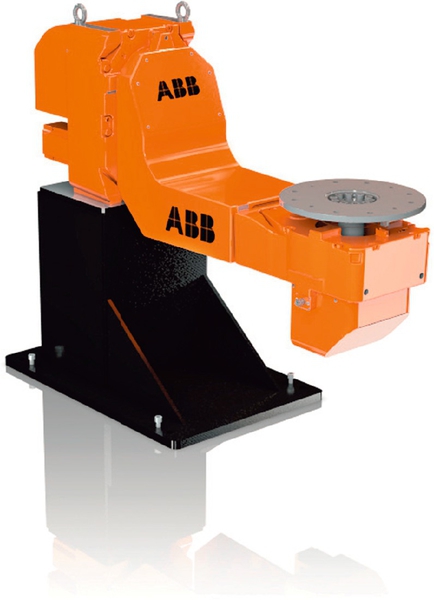
It is often necessary to reorientate the part during the process to provide access for the robot to all the welds. For example, a car exhaust system consists of a number of pipes to be joined to a number of boxes. A full 360° weld around the joint between the pipes and the boxes is required. To achieve this, the parts need to be rotated to provide access for the robot. This can be achieved with a single axis servo-driven positioner. To achieve the best results, the motion of the 6-axis robot and the servo positioner need to be fully coordinated.
There are ranges of positioners with the simplest being a head and tailstock with a servo drive (Figure 3.3). These can then be built into two station positioners with two head and tailstocks being mounted onto a turntable (Figure 3.4). This provides the opportunity for the operator to be unloading and reloading one side whilst the robot is working at the other. Also, two axis positioners (Figure 3.5) are available where it is necessary to be able to orientate the part in two axes to provide access to achieve the optimum weld positions. Again, these can be configured as two station positioners. Servo-driven robot tracks are also available if required for larger parts. Robots can also be mounted overhead in an inverted position, which in some cases provides improved access to the weld joints. There are many different combinations of positions and robots available, and the selection of these for typical applications is discussed in Section 5.2.1.

The final element within the robot welding package is the torch service station (Figure 3.6). During the welding process, the weld torch will become contaminated with weld spatter and will require cleaning on a regular basis to maintain the reliability and quality of the welding process. This is achieved by an automated cleaner consisting of a router to clean the inside of the weld torch shroud and an oil spray to reduce the adhesion of the spatter. These torch service stations can also include sensing devices that check the position of the weld torch and correct for any misalignment that may have occurred due to collisions, wire stick problems (where the weld wire remains attached to the weld pool at the finish of a weld), or manual maintenance.

3.3.2 Painting
Painting tends to be considered as different from most other automated processes. This is in part from a historical perspective, in that the developers of automated paint solutions were in different businesses than those addressing other applications, but also because the requirements of the process and the language used are different from many other applications.
There are a number of different forms of automated paint equipment, such as reciprocators and electrostatic bell systems, but within the confines of this book we will concentrate on robotic paint systems. Robotic paint systems are used for a large range of products from car bodies and parts for cars to complete aircraft. One key feature of paint robots is that they are explosion proof, as they are normally used in an environment with high solvent levels. To achieve this explosion proofing the robot arms are continually purged with clean air and the controllers are modified from the standard.
There are a number of different paint processes that can be handled by robot systems, including solvent- and water-based paints as well as two-component paints and also powder paint. Each of these requires different delivery and application equipment. Robots can handle standard air atomised spray guns, electrostatic spray guns, and also electrostatic bells. The choice of spray equipment is normally determined by the process and customer requirements. Issues such as colour change are important and robots can include banks of colour change values within the arm to provide colour change close to the spray gun, minimising the time required for the changeover as well as the wasted paint. Robots can also include full process control in that the paint flow rates, atomising air, and other process parameters can be selected and controlled within the robot programme. This provides full control of the process both for specific parts and also each individual colour.
The robots can work on both moving lines and indexing lines. Full conveyor tracking can be included to ensure the robot tracks the parts correctly as they move. Robots can also be mounted on tracks to provide for tracking of the parts through the booth. For the automotive paint applications, door, bonnet (hood) and boot (trunk) lid opening devices have also been developed to provide access to the interior areas that require painting.
Painting is one of the more complex applications for robots and requires a good understanding of the process to ensure the correct functionality is included within the robot system to achieve the results required.
3.3.3 Dispensing of Adhesives and Sealants
The application of adhesives or sealants is typically via an extrusion or a spray application. Extrusion requires contact or close proximity to the surface of the part to which the material is to be applied. Whereas a spray application provides a standoff from the part and therefore provides a larger tolerance for the path accuracy relative to the seam to which the spray is to be applied.
The materials may be single-component or two-component. The single-component material may require heating to cure, in which case an oven or similar heating device may follow the application. Two-component materials commence the curing process when they are mixed and, therefore, methods of flushing the mixed components from the system are important.
A typical system would include one (single-component) or two pumps (two-component) to provide the material and possibly some form of flow control. Temperature conditioning may also be required to ensure the optimum material properties are maintained. These devices can be integrated with the robot system, particularly the flow control, if that is beneficial for the performance of the system.
3.3.4 Cutting and Material Removal
There are many different cutting and material removal techniques, most of which have been applied to robots. Cutting techniques include sawing, routing, and water jet cutting. Circular saws have been applied to robots for sprue removal in aluminium die casting applications. Routing can be achieved using either pneumatically or electrically driven tools. Electrically driven tools are normally heavier and, therefore, require robots with higher payloads. It is most important to select the correct tool for the material to be cut and then develop the system from that point. It is also important to consider the dust produced by the cutting process, mainly for operator safety but also because in some cases the robot may require additional protection. The removal of the waste material may also be important to ensure that the operation of the robot system does not become impeded by the buildup of this waste.
Water jet cutting is a good application for robots. Water jet can provide a very clean cut, particularly for moulded or formed plastic parts. A robot can provide a 3D cutting solution, which cannot be achieved in other ways. To use a robot in this environment, additional protection may be required for the robot, due to the high level of water in the cutting booth. In addition, the feed of the water to the cutting needs to be carefully considered. The pipes feeding the cutting head cannot be flexible tubes due to the high pressure required. If the robot is carrying the cutting head, this problem is normally solved by providing a coil of stainless steel tube from the shoulder of the robot to the cutting head. This allows the robot to orientate the cutting head in three dimensions with the coil winding up or unwinding depending on the direction of movement.
Other material removal applications include polishing and deburring. These often require a specific standard of surface finish and, therefore, the process and the application of the tool are very important. As mentioned above, it is necessary to define the correct tools for the application. Deburring is often accomplished with the tools mounted on the robot and, again, either pneumatically or electrically driven tools are used. Polishing is more often achieved by presenting the parts to a series of belts, each of which have different grades of abrasive. The belts are often mounted on back stand machines, which hold and drive the belt whilst providing the correct tension. Polishing mops may also be necessary to provide a final finish, which requires the robot to hold the part and withstand the force applied by the mop as it brushes the surfaces of the part.
These applications require contact between the part and the tool; therefore, some form of compliance is often necessary to accommodate for variations in the parts or the part position. This can be achieved using pneumatics, to provide compliance within the tool, or software within the robot. However, if compliance is introduced there is likely to be variability in the results because the forces applied, or the cut made to each part, will not be exactly the same. If this variability is not acceptable, it could be necessary to include force control within the robot. This is achieved by mounting a force sensor between the tool and the robot wrist. This provides feedback of the forces applied to the robot and can be used to control the robot path to achieve the desired result.
3.4 Grippers and Tool Changers
For applications such as assembly, machine tending, and general material handling, including packing, palletising, press tending, and many other applications, the gripper is one of the most important elements of the system. Although human hand-type devices are under development they are both complex and expensive. The majority of industrial automation applications do not require this level of functionality.
Grippers are developed to suit the needs of the specific application. The method of “gripping” may use a number of alternative techniques, including the two-jaw gripper, pneumatic vacuum cups, or magnets. In some cases balloons provide a very effective mechanism.
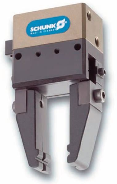
The standard two-jaw gripper (Figure 3.7) is suitable for parts that will not be damaged by the force required to hold them. This force can be generated by pneumatics, electric drives, or hydraulics if a very high force is required. Standard gripper modules can be purchased from catalogues with the only work required being the design of the gripper jaws to suit the parts to be picked. These, or variations of these, tend to be used for machine tending applications.
Pneumatic vacuum cups are widely used for handling flat parts as well as boxes and similar objects. They are very effective, quick to operate, and normally do not damage the surface of the part being picked. The size of the vacuum cups should be kept to a minimum because larger cups take longer for the air to be evacuated from the cup impacting cycle time. The material of the cup should also be considered, particularly in relation to the temperature at which the system will operate. Rubbers that work well within vacuum grippers at 20°C can be very hard and completely ineffective at 4°C, which may be the temperature of the packing hall within which the robot system is to operate.
Vacuum grippers can also provide flexibility in that an array of cups can be included within the gripper, which is selectable to suit the parts to be picked. Redundancy can also be included by providing more cups than necessary to pick each part.
The picking of sacks for palletising is often achieved by the use of clamshell grippers (Figure 3.8). Often, a vacuum gripper cannot be used because the sacks are porous and the powder within the sack would be sucked into the vacuum system. Clamshell grippers include a number of fingers that close under the sack from both sides, holding the sack underneath and, therefore, supporting this nonrigid product. To place the sack on the pallet the fingers open, basically dropping the sack onto the pallet. Although the sack is not positioned precisely, the dropping does assist in distributing the material within the sack more evenly.

Magnets are sometimes used for ferrous parts that are difficult to pick in other ways; for example, they have been used for the de-palletising of layers of unfilled tins. These would have proven very difficult to reliably pick any other way, but the magnets operated very successfully. It is worth noting that the gripper weighed much more than the parts being picked which led to the selection of a large robot to handle the required payload.
There are also more specialist grippers, such as balloons, which have been used to pick bottles. The balloon lowers into the bottle and is then inflated. This provides a very secure hold on the bottle. The handling of baked muffins is achieved by pushing a number of curved pins into the top of the muffin. These successfully hold the muffin, and the very small holes left by the pins are not visible to the consumer. Special pneumatic grippers have also been developed for picking objects with uneven surfaces, including poppadoms (thin, circular South Asian bread).
For some applications it is necessary to be able to carry multiple grippers or tools on the same robot. In some cases these can be mounted on the wrist without causing any problems of either load carrying capacity or interference with each other. In other cases this is not possible and tool changers need to be used. These are off-the-shelf products that are provided with two halves, one for the robot and one for the tool or gripper. They come in different sizes to suit different tool weights and are also able to transfer electrical power, air, and digital signals within the changer.
The actuation within the gripper is often provided by pneumatics, mainly because this minimises the weight of the gripper. Hydraulics can be used if high gripping forces are required. Electric motors are also used, including the use of servo drives when more precise control is required. However, there are cost and weight penalties when using electric drives. Hydraulics introduces a potential maintenance or reliability issue. Sensors can also be mounted on grippers to detect correct part pick up and put down as well as correct operation of elements of the gripper. Sensors can assist with the overall reliability and performance of the system; for example, by minimising the risk of mishandled parts, but they also add complexity to the gripper.
It should be noted that the gripper is the contact element of a system and, therefore, the most at risk from wear or damage. It is important that the mounting includes dowel locations to allow the gripper to be removed and replaced in a repeatable position. The gripper can then be removed for maintenance or repair and when replaced it will not be necessary to reteach any of the robot path or positions. The key to successful gripper design is to keep the gripper as simple as possible whilst still meeting the needs of the application.
3.5 Tooling and Fixturing
Robots are repeatable but to provide the required results the parts to be processed also need to be located in a repeatable position. The tooling or fixturing is used to hold the parts to ensure they are correctly located in repeatable positions, which then allows the robot to perform the required operations and achieve the desired results.
Arc welding is an application where fixtures are particularly critical. The fixtures are required to hold a number of parts together to achieve repeatable positions of the weld seams and also repeatable geometry of the seam; for example, the size of the gap to be welded. However, the fixtures must also provide control of the important dimensions of the part. For example, an exhaust system consists of a number of subassemblies including bent pipes, catalyst, and silencer boxes. The most important overall dimensions are the position of the front of the system, where it would join the engine, and the position of the rear pipe, where it appears below the rear bumper. The remainder of the system can accept reasonably wide tolerances; however, for welding, the positions of the weld joints between each pipe and box are critical. The fixtures need to be able to hold the overall dimensions and, at the same time, provide repeatable positions of the seam to be welded to the robot.
In addition the fixture must provide ease of loading and unloading. One particular issue with welding fixtures is that the part will expand during welding due to the heat provided by the welding process. The part will not have cooled when it is unloaded and, therefore, will still be in an expanded state. The fixtures have to be designed to ensure the part can easily be removed even if warm after welding.
The fixtures will include tooling locations to match the geometry of the part at that position and a clamp to then hold the part in place. A number of different clamp types can be used. The simplest form is manual on/off clamps. These are low cost but are very dependent on the operator closing all clamps correctly.
The next step in cost and complexity is manual on with air backup and automatic off. These clamps are closed manually, but when the system start signal is initiated air pressure is applied to the clamps to ensure they are pushed closed; they can then be automatically opened when the cycle is complete. These clamps provide the benefit of greater certainty on the closing and reduced time for the opening, allowing the operator to unload parts more quickly.
The most expensive level of clamps is auto on and auto off. In this case, the parts are loaded into the tooling, the operator then initiates the start, and all clamps close. The main benefit is time saved both for loading and unloading. This approach also helps in terms of process reliability as the tooling needs to be a high design standard otherwise the fixture will not operate successfully. With manual clamping it is possible for the operator to make the system work even if the tooling design is poor. An automated clamping system does not provide this capability.
It is also possible to include sensors within the fixturing. These could be part-present sensors to ensure all the parts are correctly loaded. Sensors can also be included on the clamps to ensure they are operating correctly. For welding systems, the sensors need to be weld-immune to ensure reliability.
Tooling is required to hold a part in position; for example, to hold a panel for an adhesive application. Clamps are not always required for noncontact processes or when little or no force is applied to the part. For processes such as routing, a force is applied. The tooling is normally designed to the shape of the part to provide a repeatable location. Clamps or vacuum can then be used to hold the part in place and withstand the forces applied to the part during the process if this is required.
It is important to consider the material used to produce the tooling locations. If the application is welding these will normally be steel because they must be well-wearing and damage to the parts is unlikely. In some cases copper is used to help remove heat from the part and reduce the risk of weld spatter sticking to the fixture, but this will wear more quickly and will require replacement. In other applications it is important the fixture does not cause any damage to the part or the part surface and in this case engineered plastics are often used.
In many systems flexibility is required. This can require the changing of fixtures or tooling from those for one part to a new set for a different part. If this flexibility is required, the fixtures or tooling are built up on a single plate or structure. This is mounted into the robot system using doweled positions as datums. This allows a fixture or tooling plate to be removed and replaced in the same position. Following a changeover, the robot programmes that have been previously taught can then operate without any need for reteaching. It is also important in this case that the design of the fixtures provides for easy storage (e.g., on flat plates); otherwise, they can be damaged when not in use on the robot system.
It is most important that the fixtures or tooling be reliable. These are often the most bespoke elements of the robot system. Generally, simple solutions are the most reliable but additional functionality, such as sensors, can minimise the risk of any operator mistakes. It is also beneficial if poke yoke principles can be practised to ensure only the correct parts can be loaded, particularly if the same robot cell is producing a number of different variants of product. The fixturing and tooling cost can often be a significant proportion of the cost of a robot cell, particularly because this is where most of the design costs are required. Simple solutions will be lower cost but it should always be noted that any robot cell will only be as good as the parts presentation. It is therefore worthwhile investing in the tooling and fixturing to ensure the desired output is both achieved and maintained.
3.6 Assembly Automation Components
A typical assembly system is built around a mechanism for moving the parts between the various stations at which the assembly operations take place. These operations may include adding of parts to the assembly, mechanical joining, such as riveting or screw driving, or other joining techniques, such as welding and adhesives, as well as application of seals, testing, and packaging. Testing may include electrical tests, leak tests, or visual checks, using vision, to ensure the final assembly meets the required standard and performance.
These mechanisms are often conveyors, either indexing or continuous with stop stations. The assemblies are typically held on platens that carry the fixtures onto which the parts are assembled. These are normally dedicated to the part, and a system may carry a number of the same platens/fixtures or, if a range of parts is to be produced, there will be a number of each type of platen/fixture within the system. In this latter case identification, for example, using barcodes, is required at each station to ensure the appropriate operations are performed for the type of part being presented. Each discrete operation is allocated to a specific station with the required equipment grouped at that station. To maximise the output of the system there should be enough platens within the system to ensure that no station ever waits for a platen and each station operates effectively.
Conveyor systems may take the form of a straight line, often used for indexing systems, with the initial part loading at one end and assembly off-loading at the other end. Alternatively loops can be used, typically for continuous conveyor systems. With the latter approach, it is relatively easy to include one or more manual stations within the loop to provide for part loading and unloading and also to include manual operations where the automation of these would either be too complex or too expensive.
Many of the more dedicated assembly systems are built around a rotary table, rather than a conveyor. In this case, multiple fixtures are located around the periphery of a rotary table and the equipment required for each operation is grouped at points around the table. The table would index once all the operations have been completed, moving each part onto the next stage. It is also possible to use continuously moving rotary tables with the operations being performed on the parts as they are moving. This provides for high throughput because no time is lost during indexing, but the systems are much more complex. Also it is not always feasible to perform operations on moving parts, which may be a constraint. Rotary table systems are more compact, generally lower cost than conveyor systems and can provide high throughput. However, it is not really feasible to include manual operations, and maintenance can be difficult as there is no easy access to the equipment.
An alternative approach is to build the assembly system around a robot. The robot would provide the movement of the parts through the assembly process. SCARA robots are often used for these tasks because of their high speed and compact design (see Section 2.1.2). The use of a robot provides greater flexibility because parts can be taken through different routes, depending on the requirements of the assembly process, or additional parallel stations can be more easily incorporated for operations that take the longest time. The use of the robot also provides better future proofing because it is less expensive to change the system for future product redesigns than in a more dedicated system. However, the robot approach is normally more suited for assembly operations that require a lower throughput.
Whichever route is taken for the main transport of the parts through the assembly cell, a number of other items of equipment are required to provide the functionality necessary for each operation. These may include bowl feeders or other forms of feed devices (see Section 3.1.3) to input components into the system. There may be simple pick and place devices to take the output from the feed mechanisms to place onto the assembly. There is a number of components available, ranging from single axis actuators, both pneumatic and electric, to multiaxis devices with both rotary and linear axes. These devices are equipped with grippers or carry other tools to perform the operation required. Appropriate sensors are included to provide for the sequencing of the devices and appropriate checking to ensure operations were completed successfully. A complete system could therefore be a very complex machine, generally built from standard components but with a bespoke design to suit the needs of the assembly process.
3.7 System Controls
The system control of an automation system is present to provide a number of key functions:
• Overall control of the elements of the cell or system to ensure they all operate as planned and in the correct sequence.
• Presentation of data regarding the cell or system to supervisors and operators and/or higher-level control systems such as a factorywide manufacturing execution system (MES).
• Assistance to maintenance people in the event of a fault, displaying status and error information, to provide guidance in identifying and correcting the fault.
• Overall safety functionality to ensure the cell or system can be operated and maintained in a safe manner.
The first programmable logic controller (PLC) was developed in the late 1960s with the purpose of providing this type of control. Prior to the PLC this functionality was provided by banks of hardwired relays, which were often complex, difficult to maintain and also difficult to modify for changes in the system. The PLC provided the same functionality but within software rather than banks of relays with the PLC being programmed using ladder logic, a programming method that replicated the functionality of relays and was, therefore, easy to understand and use.
PLCs are still used to provide overall system control and both their capability and programming has developed significantly. PLCs today range from microunits with only a few digital inputs and outputs (I/O) to much larger devices that can handle hundreds of I/O, analogue functions and the more advanced network interfaces such as Profibus and Ethernet (see below).
A typical robot system may well include a PLC to provide the overall control. This will also interface to a human machine interface (HMI) to provide information to the operator, maintenance, and other personnel. A typical HMI will include a screen, which is used to graphically display the status of the cell and the equipment within the cell as well as production and process information. It will also include functionality to interrogate aspects of the system, fault find and adjust important process and application parameters. The HMI will also provide the overall control, including functions such as start, stop, reset, and so on.
Within smaller robot systems, it is also feasible for the robot to provide the same functionality; therefore, a PLC may not be required. This would provide a lower-cost solution but is not always preferred because it becomes necessary for the customer’s personnel to access the robot programs and can be perceived as too complicated. They may be more comfortable accessing a PLC, due to their greater experience with them; therefore, PLCs are often included to maintain a separation between the robot and its programme and the overall system control. On larger systems, for example, with multiple robots, a PLC is normally preferred as one piece of equipment which can provide the overall control rather than being dependent on the controls being distributed across a number of different elements of the system.
At the basic level the various items of equipment within the cell are interfaced to the PLC via digital I/O. Sensors are often located throughout the system to check the operating sequence and ensure a step has been completed prior to moving to the next step. These sensors might be located on conveyors to ensure parts are in position, on fixtures to ensure all parts are loaded correctly or within grippers to check parts have been picked up and put down. Robots would also provide signals to the PLC at appropriate points to indicate where they are in their programme as well as waiting for signals from the PLC before moving on to the next step.
In addition it is also possible to locate I/O blocks remotely from the host device, the PLC, or the robot controller. For example, an I/O block could be mounted on a fixture to connect to all the sensors and any actuators on the fixture. These connections may be via individual wires. The signal to the host device from the I/O block may then be transmitted via a single wire; therefore, reducing the wiring from the fixture to the host. It may reduce cost, particularly if significant distances are involved, but it does improve reliability as well as ease of maintenance and repair.
Using discrete I/O can lead to a large number of signals being routed around the cell. Both robots and PLCs are equipped with I/O blocks that typically each handle 16 inputs and 16 outputs. If a large number of signals are required this can lead to a large number of I/O blocks both within the robot and PLC and there are limits to the number of I/O blocks that can be fitted. Systems with large amounts of I/O are also more expensive to install and more complex to maintain. To alleviate this problem, networks were developed to define standards for the interfacing of equipment with the intention of ensuring compatibility between different pieces of equipment. The original industrial network was the Manufacturing Automation Protocol (MAP), originally defined by General Motors in 1982. Since that time various networks have been defined and used including Profibus and Ethernet. Unfortunately there are still some challenges as the major suppliers of PLCs tend to support a specific version of a network, reducing compatibility with the products aligned with their competitors.
Networks have also become multilayer. For example, a typical three layer network comprises:
• Device Net – a bus system that connects low-level devices directly to factory floor controllers and eliminates the hardwiring to I/O modules.
• Control Net – a higher-level network for interfacing the various machines within an automation system or on the shop floor. This may include robots, machine tools, HMIs, and PLCs.
• Ethernet – a standard information network for the fast exchange of large amounts of data between PLCs, supervisory control and data acquisition systems, as well as factorywide MES. This would provide for the overall communication and operation of automation systems across the factory floor.
Each level operates to a defined standard and products are available that meet these standards; therefore, it is possible to select the appropriate products and place these within the network knowing they will operate correctly.
The control system is also involved in the monitoring and maintenance of the safety circuits. This is discussed further in the next section. In summary, the control system provides the overall control for the automation system and also provides access to the functionality for the operator and maintenance personnel. It is therefore a key element of the system. The configuration, particularly the software, is often bespoke because the requirements of each application and customer are normally different. It is therefore important that it be designed in a logical way and fully commented and documented to allow others to understand how to interrogate the system and correct faults. Many companies now apply standard approaches to the creation of the software making it easier for others to understand and modify the code in the future.
3.8 Safety and Guarding
The primary role of the safety system is to ensure that no personnel will endanger themselves through the operation, use, or maintenance of an automation system. There are standards that explain what is required to provide this safe operating environment. Country standards may be applicable as well as standards provided by the customer. These standards are often guidelines rather than definitive statements, and require an assessment of the risk, normally by the automation supplier, of the potential human interfaces with the cell, including operators, programmers, maintenance personnel, as well as third parties. The assessment should cover all potential risks that are to be removed or minimised as appropriate by the application of the safety systems and guarding. In some cases, the assessment will be more onerous; for example, with, laser applications, due to the greater risk associated with the use of this type of equipment.
The main guarding is normally formed by a fixed guard surrounding the cell. This is normally 2 m high with a small gap allowed at the bottom. The surround is normally made from posts fixed to the floor to which are attached infill panels. The panels can be sheet metal, weld mesh, Perspex, or other forms of plastic sheet.
The choice of material is normally dependent on the application and customer’s preference. For arc welding applications it is also necessary to protect personnel from the glare of the welding arc; therefore, solid panels, or weld mesh backed by weld screen material, are used. Plastic panels may well be used in cleaner environments as they provide an overall better finish to the cell but can be more easily scratched. Weld mesh is lower cost and is often used in more arduous environments where plastic panels would quickly deteriorate.
Laser applications normally require a completely light-tight box to ensure there is no possibility of transmitting the laser beam outside the cell. A recent high-power laser application provided a greater challenge in that the laser, if directed at the wall of the box, even for a very short period, would cut through the wall and therefore be transmitted outside the box. To solve this problem, the inside wall of the box is completely covered with plates, which sense the impact of the laser and cause the laser to be turned off within fractions of a second, thereby making the system safe.
Having surrounded the automation, it is then necessary to provide access. The simplest form of access is for maintenance and programming. This is infrequent and is normally accomplished by one or more access doors. These doors are interlocked to the control system so that the system cannot be operated in automatic with one of these doors open. There does need to be the provision to provide power to the machinery when access doors are open to allow the programmers or maintenance personnel to perform their required activities. There are many different solutions, but one of the most common is a key exchange system. The person enters a mechanical key into a box on the access door, which then releases a second key and allows the door to be opened. The person can then place this key into a second box inside the cell, which then allows the equipment within the cell to be operated from within the cell but not from outside. It is, therefore, under the control of the person within the cell. The cell cannot be operated from outside until the sequence has been reversed and the keys returned to their correct locations. This type of approach does require care on larger systems with multiple robots because multiple access doors may be required and multiple personnel can be within the guard at the same time. It is important that the system should not be locked with somebody still within the cell. Some companies address this by using padlocks, with individual keys allocated to each person to ensure the system cannot be closed up and returned to automatic without all personnel having exited the system.
The other area where access is normally required is for the loading and unloading of parts into the system. The requirements of the guarding for this point of entry are dependent on the equipment with which the operator comes into contact. Typical equipment used are doors, lightguards, floor mats, or scanning area guards.
Doors can be sliding, rise and fall, automatic or manually operated. These are generally built into the guard surround and provide a physical barrier between the operator and the automation when the door is shut. If the door is automatic a safety edge, that is a rubber strip that senses an obstruction, may need to be included to ensure the door cannot trap the operator in any way. When the door is open, the cell must be designed so the operator is not able to access the cell and cannot reach any moving or dangerous equipment. Doors are often used where the operator is loading to a fixture mounted on a table or a positioner. The positioner or table provides a barrier between the operator and the functioning part of the cell.
Lightguards are often used where larger areas of access are required or doors are impractical. A lightguard consists of two columns, one of which carries a series of light transmitters and the other a matching series of receivers. For a loading area, each column is mounted on either side of the area and if any of the light beams are broken, that is, the light does not reach the receiver, then the lightguard will cause a stop of the system. The output can be muted at appropriate times; for example, when it is safe to enter the area.
There are two other issues that are important. It is often necessary to determine the stopping distance of the machinery with which the operator interfaces and the distance to any trapping points. This then determines the position of the lightguard; that is, how far from the equipment the lightguards need to be placed. This is to ensure that if any personnel entered through the lightguard, the equipment would have ceased moving before the personnel reached the moving equipment.
The other issue that is important is it must not be possible for personnel to stand on the inside of the area guarded by the light guard and the system to continue to operate. This is normally addressed in two ways. First, a physical barrier is included within the cell to prevent personnel from entering through the lightguard to the load/unload area and then moving farther into the cell. The second is to either tilt the lightguards at 45° so they cover the area or to place a horizontal and vertical lightguard to ensure the area is covered. It is also feasible to use floor mats that, when stepped on, will sense the presence of the operator. However, these can be more easily damaged and become unreliable.
An alternative approach is to use scanning area guards. These guards transmit a laser beam, which is scanned across an area in front of the sensor. They then receive the return beam reflected from the objects within the range of the sensor. The sensor can be programmed to define the signal profile for a normal situation; that is, a clear load/unload area. They can, therefore, detect changes to this and cause a stop if the floor area has been entered.
It is also possible, in conjunction with software within the robot, to define specific areas within the field of the sensor. These areas are then used to cause specific actions by the robot in the event of personnel entering each of these areas. Specific robot software, such as ABB’s Safemove, which meets the safety standard requirements, is required for the safe implementation of this functionality. As an illustration, two areas within the sensor view may be defined, an outer area and an inner area within the reach of the robot. If an operator enters the first area, the robot would then slow down and if the operator enters the second area it may stop in a safe mode, but not an emergency stop. Once the operator exits the relevant area the robot would return to its previous operating mode; that is, slow speed if the operator remains in the first area or full speed once the operator exits the first area. This approach can be useful for applications where interaction between the operator and the robot may be required during the robot cycle; for example, the loading of a part during the robot operation where the use of more conventional guards may either cause time delays or be impractical.
Another common guarding requirement is to provide for parts to pass into or out of a cell automatically but, at the same time, prevent personnel entry through the same area. An example of this is palletising systems where cartons enter the cell via a conveyor and both empty and full pallets need to exit the cell. The carton entry can be guarded using a tunnel constructed of fixed guards. The tunnel is built around the conveyor, large enough to permit entry of the cartons but small enough to prevent personnel access. It would also be long enough to prevent personnel from reaching into the cell.
The guarding of the pallet entry and exit is a little more complex. The pallets are typically fed in and out via a roller conveyor. Two sets of lightguards are mounted across the access point, providing an outer and inner guard. These are linked and muted at the appropriate times. For example, when the pallet is moving out of the system the inner lightguard is muted initially until the pallet has passed through, at which point it becomes active again and the outer lightguard is muted until the pallet has completely exited the cell. Therefore, the cell is guarded at all times, either via the inner or outer lightguard.
Guarding and safety is a very important aspect of all robot systems. The equipment can be dangerous if not treated appropriately and all potential risks to personnel must be addressed. Appropriate training is also required for the different types of personnel to ensure they operate the equipment correctly and also understand the safety aspects of the system. This is particularly true of maintenance and programming personnel who may well be working within the guard and are, therefore, at greater risk.
3.9 Summary
The key elements of a number of typical automation systems have been outlined and some of the most important issues identified. It should be apparent that there are many different types of equipment that can be used, depending on the specific application. For each application, there are also a number of choices to be made that can have significant impact both on the cost and also the ultimate success of a project. It is, therefore, unlikely that any one person will have detailed knowledge of all the types of equipment and applications. Suppliers tend to specialise in certain applications and customers, by the nature of their business, and are also unlikely to cover more than a few applications.
It is most important when embarking on a specific automation project that good knowledge of all of the particular elements of a system is obtained, either directly or by bringing in experts as consultants or suppliers to assist the project from the initial specification through to implementation. The key to success is often not the existing knowledge or expertise but knowing what you do not know and, therefore, where assistance and advice is required.