Developing a Solution
Abstract
This chapter outlines the steps required to develop the concept for a potential automation application. The initial step is the definition of the key parameters, such as the part details and production rates. We then discuss the development of the initial concept in terms of the main applications, including arc welding, machine tool tending, palletising, packing, and assembly, before providing information for other applications. We also identify the main control and safety issues considered at the concept stage, as well as the use of testing and simulation in refining the initial concept.
Irrespective of application or complexity, every robot system should be developed using a number of steps and iterations in order to achieve the optimal outcome. The goal should always be the on-time implementation of a successful system within budget. A successful system is one that achieves the desired production rate and quality objectives with the anticipated financial return. Many factors can impact the financial return, and we discuss these factors further in Chapter 7.
This chapter illustrates the steps required to achieve a successful conclusion to the project, highlighting the main pitfalls and how these can be avoided. Nothing about a robot system makes its development and implementation significantly different from any major capital project, other than the lack of awareness about what a robot can do and, more importantly, what it cannot, especially in relation to human workers. Robots do not have the same intelligence and sensory abilities as manual labour, and, therefore, they cannot be a direct replacement for human workers. The design of the solution needs to suit the capabilities of the robot system in relation to the parts and the process. This can, and often does, require changes to the manual process in order to suit a robotic process, but the overall result is often an improvement.
It is also worth noting that the introduction of a new robot to replace an older robot is a much simpler proposition. In this case, the majority of the process and application are already defined, although a detailed study may identify how the performance of the new machine could provide opportunities for improved output or quality from the system. The decision process should also consider the reuse of the existing equipment or the replacement of this equipment, as well as the robot. The older equipment may compromise the performance of the new robot, and, therefore, the short-term savings may be offset by increased expenditure in the longer term. It is also necessary to consider safety because standards often change from the date when the original system was installed. The guarding and safety system may need to be modified and updated to meet the current standards that will apply due to the introduction of the new robot. Although a robot replacement does appear to be straightforward, a detailed investigation is required. Without appropriate study, the cost of a robot replacement can quickly escalate, leading to problems with the agreed-upon budget.
5.1 Determining Application Parameters
The first step toward the development of a successful project is to obtain a detailed understanding of the current application. This may seem obvious, but details can be missed at this stage, which may not become apparent until commissioning, and such oversights can have a very significant impact on the success or cost of a project. The following discussion is based on an ideal situation because all the information is often not available. However, engineers should obtain as much of the important information as possible, while also developing an understanding of the risk related to any unknowns.
First, the engineer should obtain all relevant drawings and documentation for the parts to be produced, as well as the basic process details. For example, if considering a welding project, the engineer must ascertain the type of welding process, size and type of wire, welding gas, weld sizes, and specification. It can often be beneficial to view the actual parts and the current operation if possible. One of the most important issues to identify is the variability of the parts, as presented to this operation. This could include dimensional variances, variability of surface finish, cleanliness, and part presentation. The key is to understand the reality rather than what may be defined on a drawing or within a specification. An understanding of the important parameters is also useful as this will vary for different applications, processes, and solutions.
For example, for a palletising application, the security of the carton-closing method is important if vacuum is used to pick the boxes. For a welding application, the processes and machines used to prepare the subassemblies are important because they provide a guide to the repeatability of the parts and, therefore, the repeatability of the weld joints. In this case laser-cutting the parts, followed by bending on modern press brakes, is likely to provide repeatable parts that can be robot-welded. Part dimensional variances and the cleanliness of the parts may be particularly important for an assembly system. The method of presenting parts to a machine loading application may be important. It is very difficult to provide an all-encompassing list because the parameters depend on the process to be performed, the types of parts and the proposed automation solution. Further details are discussed in Chapter 6, which covers the development of a specification. If this is done correctly, all these points are addressed.
If possible, the engineer should also discuss the application with the person currently performing the process. Operators are very flexible and generally do solve problems. They may be doing something within their activity that makes the job either possible or easier, but this adaptation might not be detailed on any of the process documentation or work plans. For example, the operator may make a change to accommodate input variability that is not identified on the relevant documentation. The operator may also solve part fit-up problems or other problems may have been identified and solved by production without informing other parts of the organisation. Without knowledge of these activities, the engineer may devise an automated solution that costs more than anticipated due to the additional work or equipment required to achieve a working system, or the design may actually fail to perform as required.
The next step is to define the required production rate, number of shifts the equipment is to be used for, number of hours per shift, and number of working weeks per year. The objective is to determine the cycle time required to achieve the necessary production output. During this stage, the engineer also tries to establish the anticipated efficiency with which the robot cell is expected to operate. This includes downtime due to breakdowns, planned maintenance, and replenishment of consumables, as well as the downtime of other facilities, which could affect the uptime of the robot cell. This other downtime may include lunch breaks and other stoppage times if the cell is not able to operate without operator support. Based on this information, the engineer can define a target cycle time that will achieve the desired production rate at the anticipated efficiency. This is basically:
The efficiency factor used for these calculations may well be as low as 85%. The mean time between failures for a typical robot suggests that the efficiency should be in the high 90s, but the efficiency factors for each element of the system multiply together, which reduces the overall efficiency, and it is normally better to be conservative, particularly during the early stages of the project. In addition to the cycle time, the engineer must understand the required operations on the parts and the relevant process parameters. For an arc welding application, this includes the location of the welds, the weld sizes and lengths, details of the weld joints, the physical access to the welds, and the size and weight of the parts.
5.2 Initial Concept Design
The initial concept design often results from previous experience as much as it does from a detailed study of the application. Having previously viewed similar applications, the engineer may be able to suggest an outline concept as a possible solution. The concept design is an iterative process, however, and having an outline concept as a starting point can be very helpful. The thought process by which this initial concept is developed can depend on the application being considered. The following sections provide some guidance for concept development and the main issues related to designing a solution for the main robot applications. These applications are arc welding, machine tool tending, palletising, packing, and assembly. We also provide more general comments on other applications, including spot and laser welding, painting and dispensing, as well as material removal.
5.2.1 Arc Welding
The simplest arc welding system consists of a robot and welding package working on two tables. The fixtures to locate the parts are mounted on these tables. Two tables are included to allow the operator to unload and reload one table whilst the robot is welding at the other. Provided the robot cycle time is longer than the operator unload and load times, the robot works continuously, and the output of the robot is maximised.
An alternative design might include a manual turntable in place of the two fixed tables. This potentially has the benefit of reducing the need for operator movement, because the worker does not need to walk between the two fixed stations. It also simplifies the guarding and potentially improves the robot access to the part, particularly from the sides, which are completely open in the case of a turntable. The turntable may be beneficial if the robot is only producing one part at a time. In other words, the two fixtures are the same. Therefore, the operator can load from the same bins and also unload the completed parts to the same place. If different parts are being produced, two fixed tables may be more effective because these provide two distinct stations, reducing the congestion around one station and the risk of mixing parts. The time to change between stations is also reduced because the manual turntable depends on the operator to make the turn, whereas the robot can switch between fixed stations as soon as it is ready.
A slightly more complex system includes a powered turntable. This removes the dependence on the operator for the turning, and it may be required if heavier or larger parts are involved. It does provide improved access to the parts in the same way as a manual turntable, but it complicates the guarding because the turntable also needs to be guarded, increasing the size of the cell. The choice between fixed table, manual turntables, and powered turntables can often result from preference and a perception as to which is more appropriate for a particular facility.
In designing an arc welding system, the engineer must initially consider the requirement for orientation of the part during the welding process. It may be necessary to position the weld joint in a preferred orientation (e.g. 45°) to optimise the weld process and, particularly, to avoid welding vertically upwards. In both such cases, a positioner may be used to provide the optimum conditions for welding rather than access for the robot. In some cases it is possible to include a two-stage process with parts welded in one orientation in the first stage and then in a different orientation in the second stage. The operator can turn the parts between the stages. For example, the operator could use a fixed table with two fixture locations. During the load cycle, the operator removes the fully welded part from the second location, unloads the part from the first location, reorientates the part and places it into the second location and then loads new parts into the first location. Therefore, for each cycle, a new part is loaded, and a fully welded part is produced. It is also be feasible for additional parts to be loaded into the second fixture location if required.
This orientation capability may be required because a weld needs to be made around a tube or a box. It may be preferable to perform this weld in one pass to avoid starts and stops in the weld path. For example, if the weld is to be leak proof, starts and stops should be minimised. Therefore, to provide access all the way round the part, the part must be reorientated during the weld process. If part reorientation is required during the weld process, or it is not possible to manually reorientate parts between cycles (e.g. if the parts are too heavy or the reorientation is too frequent), then a positioner may be required in the cell. The basic positioner consists of a headstock carrying a single servo-driven axis and a tailstock (Figure 3.3). The fixture is typically located between the head and tailstocks and can therefore be rotated using the servo-controlled axis under control of the robot programme. The most important issues to be considered are the weight and size of the parts. These single-axis positioners are available in a range of sizes according to the weight capacity, the maximum swing diameter, and the maximum length. The weight capacity must be enough to accommodate both the weight of the part and the fixture, which is often heavier than the part. The swing diameter must be large enough to accommodate the maximum diameter of the part and fixture combined, and the length must allow the fixture to fit between the head- and tailstocks.
If these single-axis positioners are required, the engineer often includes two positioners, to provide for unloading and reloading at one whilst the robot welds at the other, in the same way as two fixed tables. These can be positioned on either side of the robot, but this arrangement does complicate the guarding because suitable screening must be included to protect the operator from arc light being produced at the operating station. Locating the positioners on either side does separate the two stations, however, which can be beneficial if different parts are being processed, reducing congestion at the load stations and also potentially improving the flow of parts around the cell. But it also potentially increases the travel distance for the operator if he or she is working on both stations.
An alternative approach is to place the two positioners side by side, which simplifies the guarding but requires the robot to be mounted on a servo-driven track to ensure it has the reach needed to access both positioners, increasing the cost. For longer parts, the use of a track may be necessary anyway, so this may not be a major implication for the solution.
There are also two station versions of these single-axis positioners (Figure 3.4). In effect, these are two single-axis positioners mounted on a turntable. The same issues, weight capacity and size, apply regarding the selection of the most appropriate as for the single axis positioners. The swing radius of the turntable must also be considered to ensure the robot is positioned outside this swing radius. This often means the robot has to be located further from the parts to be welded, and, therefore, a larger robot may be required. The swing radius also governs the maximum length of part that can be accommodated; as a result these two-station positioners are only appropriate for smaller parts, otherwise the swing radius becomes impractical. Alternatively, the robot can be mounted overhead so that it is away from the swing of the turntable, but this arrangement introduces other issues, particularly regarding maintenance.
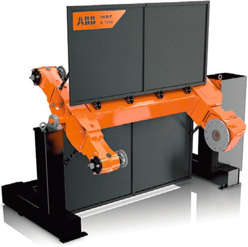
A further type is the H-style positioner (Figure 5.1). This is similar because it carries two single-axis positioners, but instead of rotating around a vertical axis, the index rotates around a horizontal axis. Therefore, the robot can be positioned close to the welding station. It is also possible to accommodate longer parts because the length is not constrained by the swing radius. Both these types of two-station positioners include a weld screen between the stations that protects the operator from the arc glare produced as the robot is welding.
There are also two-axis positioners that can rotate the part in two directions (Figure 3.5). These can orientate a specific weld to exactly the orientation required, and they are typically used with subassemblies for off-road vehicles, often consisting of thicker metal parts and requiring multipass welding. These two-axis positioners are also available as two-station devices with two mounted either side of a turntable. This positioner is therefore be a four-axis system.
The cost of the positioners can add significant cost to the cell. In addition, the fixtures can be expensive items. If the production rate and cycle time are such that more than one robot is required, it is often beneficial to include two robots within one cell. This may remove a requirement for a track, because the two robots can cover a larger area, and it is obviously less expensive than two separate systems. If two robots are included, the work load between the robots must be balanced in order to ensure that the output of the cell is maximised.
At this stage, the engineer has probably not designed the fixtures, but, based on experience, the engineer can often estimate the weight and size for the parts to be welded. The type of positioner and solution design may have some influence on the fixture design, and therefore, the engineer must define a basic concept before the fixtures can be designed.
As mentioned above, the engineer must consider how the guarding can be designed to ensure that the system can operate safely. It may also be necessary to consider how the parts will be unloaded and reloaded to the system. Some parts can be heavy, requiring assisted lifting or overhead cranes, and access needs to be provided to the load/unload stations for this equipment. It may be necessary to consider the loading on the positioner during the load/unload process. Two-station positioners might be affected by the physical loading of very heavy parts. If vibration of the positioner is created at the load station, it can be transmitted to the weld station, resulting in potential problems with the welds. This should be considered as part of the concept stage and may suggest the use of single-station positioners.
It is also important to consider the flow of parts through the robot cell, both from and to adjacent operations. This is partly to minimise congestion, to ensure that the part feeding is not a problem, and also to help the operators achieve required tasks without difficulty. To this end, the design can include a combination of fixed tables, turntables, and positioners to provide what is required. Normally, a system contains a minimum of two stations, but, in some cases, more may be beneficial. For example, if frequent fixture changes are required, three or four stations may be included. With suitable guarding, this allows the robot and operator to work on two stations whilst fixture changeovers are being performed on the others.
Once the basic layout is defined, including the selection of positioner, the engineer should consider the type of welding equipment. First, the engineer defines the weld process package needed to meet the requirements of the application. The main robot issue at this stage is the weight of the welding equipment. For example, twin-wire welding equipment requires a much heavier torch than single-wire systems. This establishes the required weight capacity of the robot. The reach required of the robot is based on the parts and the part presentation, or the choice of positioner. Using this information, the engineer can determine the optimum robot for the concept. As part of the consideration, the mounting of the robot should be assessed. The preference is for floor mounting, but inverted mounting can be appropriate. If inverted is the optimum, this may affect robot selection, because not all robots can be mounted in an inverted position. Finally, the engineer should define the locations of the welding power source, wire feed, and weld torch service centre.
Although there are many different selections to be made in the development of a welding solution, the constraints of the parts and production rates normally define the type of solution that is most appropriate. The type of positioner can often be determined from experience, and this then drives the rest of the solution design.
5.2.2 Machine Tool Tending
In many ways machine tending is much simpler than arc welding because there are not the same choices to be made in regard to associated equipment such as positioners. The first important issue in creating a machine tool tending application is the weight and design of the parts to be handled. The objective is often to maximise the output of the machine tool. Therefore, the time taken for unloading and reloading should be minimised. To achieve this, robots are often equipped with a double gripper so that they can remove the finished part and replace it with a new part without losing the time needed to withdraw from the machine, deposit the finished part, and collect a new part. As a result, the robot often needs to be able to carry both a finished part and a new part, as well as the dual gripper. The aperture within which the unloading/loading operation takes place (see below) may also be important. With regard to part weights, the new part weighs more than a finished part because the machining process removes some of the material of the part and therefore reduces the weight. The loading on the robot is also often offset from the centre of the wrist axis, particularly when it is only carrying one part. In addition, the size of the gripper is important because this determines where the centre of gravity of the part will be relative to the wrist. As discussed in Section 2.2, the load capacity of the robot is both a function of the weight of the part and the position of the centre of gravity with respect to the mounting flange on the wrist. In some cases, the gripping method is different for a new part and a finished part due to the operations that have been performed within the machine tool. In this case, a double gripper is still required, even if only one part is being handled at any one time.
Once the load capacity has been determined, the engineer must consider the reach. The reach is partly determined by the access into the machine tool, both in terms of the reach required to access the fixture on the machine bed or the jaws of the chuck, and the size and location of the aperture provided for loading. Not only does this have an impact on the reach of the robot, but it may also affect the design of the gripper and its ability to hold two parts. If the parts are relatively large and/or the aperture is small, the robot may not be able to access the machine with a dual gripper and orientate this gripper inside the machine whilst carrying both parts. If this is the case, the robot needs to remove one part before placing a new part into the machine. To minimise the effect of this movement on machining time, the engineer may include some buffer locations just outside the machine tool to provide temporary storage for parts. As part of this consideration, the automation of the door opening may be an issue. With some machines, the opening for an automated door is less than that of the manual door. Therefore, this detail needs to be checked and may become important.
As part of the robot reach study, the engineer must also consider the other stations or activities that the robot will address during its cycle. The parts may be presented on pallets or fed from a conveyor or stack. The finished parts may be returned to the same pallets, stacked on different pallets, or even fed out on a conveyor. These input and output stations often include some form of buffering to reduce the dependence on operator intervention. If the buffering is large enough, the system may be able to operate for extended hours without any manual intervention. This could extend to overnight or full days on Saturday and Sunday. Therefore, additional capacity can be achieved through the machine tool, without the need for personnel to be present. The main constraints to the success of this approach are the reliability of the equipment and process and the size of buffer required.
Two or more machine tools are often addressed by the same robot, with the robot taking parts from one machine and feeding them to the next. Each of these stations needs to be grouped around the robot in a logical sequence in order to minimise the time required by the robot to move between each station. The overall sizes and access also need to be determined, and from them, the engineer can define the reach of the robot. In some cases, particularly if larger machine tools are involved, the robot may be mounted on a servo-driven track to provide the overall reach required.
In some cases the robot also performs further operations, such as deburring, within its cycle. This can be achieved via a tool mounted on a stand, with the robot presenting the part to the tool whilst holding it within the gripper. Alternatively, the robot may present the part to an inspection station prior to loading it to the output device. If the robot has time available, it can engage in additional operations, built in at a relatively low cost, thus improving the overall justification for the system. The engineer must consider all of these issues prior to robot selection.
Due to other constraints within the system or the differences in the parts to be handled, the design may include tool changers. These provide the ability to automatically change grippers (see Section 3.4). There is time required for the tool change, but the system’s overall flexibility is significantly enhanced. The use of tool changers requires a rack for the various different grippers to be used, and the rack needs to be located in an appropriate position within the cell.
It may be necessary to include multiple robots within the handling system to achieve the throughput required. In this case handover stations can allow one robot to pass a part to another robot. If two or more robots are required, a better solution may be to split the systems. This has the advantage of simplifying each system, but it may increase the space required and the cost. The overall objective should be to maximise the output of the machine tools, achieving the product rate required whilst minimising the investment in the automation.
The design should always provide access to the machine tools for maintenance or fixture changeovers. Both of these functions are likely to be necessary at some time. The only point of access may well be the same aperture used by the robot to unload and reload parts. Therefore, the cell design needs to ensure that the appropriate access can be achieved, and this access provision might require assisted lifting equipment or overhead cranes for heavier parts. In some cases, if the robot is tending multiple machine tools, the guarding may have to allow manual access to an individual machine without causing the rest of the system to stop. In other words, the guarding may need to allow manual access to one machine whilst at the same time preventing robot access to that machine and also preventing manual access to other areas of the system.
The effectiveness of a machine tool-tending application normally depends on the need to unload and reload the machine as fast as possible to ensure the machine operates at the highest efficiency possible. The robot is the tool that provides this capability. It may be possible to include additional machines or operations within the robot cycle, provided the robot has time available. It may also be possible to operate unmanned working conditions, given appropriately buffered infeed and outfeed. This can increase the capacity of the machine tools for limited additional costs, and it can remove the need for further investment in additional machine tools.
5.2.3 Palletising
Palletising normally involves picking boxes from an input conveyor and placing them onto a pallet. In most cases a four-axis robot is used because it is not necessary to reorientate the boxes other than by rotating them about the vertical axis, and therefore, four axes are all that is required. The four-axis solution provides a larger carrying capacity than the equivalent six-axis machine, as well as a lower price. Both features principally result from the absence of the fifth and sixth axes of the wrist.
In most cases, the selection of the robot is reasonably simple because it is determined by the weight capacity and the reach required. The reach is partly driven by the size of the pallet, although most palletising robots can palletise to the standard sizes of pallet. When determining reach, the engineer should focus on the height of the full pallet to ensure the robot can achieve a full layer at this stack height. The maximum is normally 2 m, although in many cases the stack height is lower than this.
The weight capacity requirement is driven partly by the weight of each individual object (box, sack, or other item) to be palletised, the gripping method and the number of each item being picked. The number of each item being picked is normally determined by the throughput required. To achieve the throughput, the system may palletise two or more items or even a complete layer within one cycle. This has implications on the gripper and the feeding system. The simplest solution involves one box arriving at a pick station, located via a pusher to ensure it is consistently positioned, picked by the robot, and placed on the stack on a pallet. The gripper often utilises pneumatics to provide a quick and simple gripping technique. The same approach can also be used with other objects such as sacks being picked via a clam shell gripper (Figure 3.7).
If cycle time requirements result in the robot needing to pick more than one item at a time, the system often becomes more complicated. For example, with two items being picked, the part infeed system must collate the two items in a consistent position, and the gripper needs to be able to pick the two items simultaneously. In most cases the items are also placed simultaneously, although, in some cases, they may need to be placed individually. This approach can be extended to multiple items and eventually a full layer. As more items become involved, the choice of grippers is basically reduced to pneumatics only. Sometimes, due to the nature of the parts, the palletising operation is more reliable if complete layers are formed, picked, and palletised. However, if many items are to be picked in one move it is necessary for the part infeed to collate these items in a reliable and consistent format.
The infeed can therefore require careful consideration, particularly if more than one product is being fed into the system. It is quite feasible for a robot to palletise a number of different products to different pallets. The only constraint is the number of pallets the robot can reach. Normally, the maximum around any individual robot is four, but this can be extended if the robot is placed on a servo-driven track. This does increase the palletising time, however. It may be better and probably about the same cost to use two robots rather than a robot mounted on a track. The infeed can be down the same conveyor with some form of product identifier, such as bar code readers, identifying the pallet onto which the robot is to place the item. Alternatively, a robot can handle more than one input conveyor, with each input normally dedicated to one output pallet station.
The number of output stations can also vary. As mentioned above, a typical palletising robot can handle four stations unless the working envelope is extended by mounting the robot on a track. There are two issues that the engineer must consider regarding the number of output stations. The first is the number of unique pallets required. Most palletising systems place boxes from one input onto one pallet. Normally, only distribution and logistics systems require larger numbers of output pallets. The most significant issue with most palletising systems is the changeover time when a pallet is full. If only one item is being palletised to one pallet, it is feasible to have two output stations. The robot can automatically changeover to the second station and continue to palletise. At some appropriate point, an operator can arrive, remove the full pallet, and load a new pallet ready for the robot. This simple solution can be extended to four pallet stations with two input conveyors and the robot palletising two different items, one from each input, to one of two pallet stations. Providing that the operator removes the full pallet and replaces it with an empty pallet within the time taken for the robot to complete a pallet, the system continues to run without interruption.
For systems requiring frequent pallet changes or systems that do not rely on operator interaction, there are two different approaches. The first involves a pallet stack, loaded by the operator, with, say, 10 pallets, but unloaded by the robot, taking a pallet when required and placing it in the load station. The second approach is to use an automated pallet dispenser. Again, the operator loads the stack, but a new pallet is dispensed and fed via conveyor to the load station. The first approach does require some robot time to transfer the empty pallet, but the second is completely independent of the robot, and therefore, it has no impact on the palletising cycle. Both of these approaches require the full pallets to be removed from the system. The best way of reducing the system’s dependence on the operator is to include conveyors to drive the completed pallets out of the loading station. This provides a buffer, and, as long as the full pallets are removed before the next pallet is completed, there is no delay to the palletising. If this may be an issue, the buffers can be extended. It is also possible to automatically feed the completed pallets to an automated shrink wrap machine that often follows palletising.
The requirement for layer sheets also needs to be considered. These sheets are normally cardboard, and they are provided from a stack that is replenished manually. The stack needs to be within the working area of the robot, and the robot gripper needs to include the capability to pick up these sheets from the stack and place them onto the pallet stack.
One issue to address during the concepting of a palletising system is the guarding. As mentioned in Section 3.8, it is important to ensure there is no opportunity for operators to access different areas of the palletising cell. Two stage guards are often used on the output for the full pallets to ensure the pallets can exit to the area accessible by the operator for unloading, but operators are prevented from entering the cell.
Similar to other applications, the most important issue for a palletising system is achieving the required throughput. The gripping mechanism can be a challenge for palletising, dependent on the type of item to be palletised and the consistency of the presentation or packaging. The other major issue can often be space. Palletising systems can use quite a large area due to the sizes of the pallets, the conveying required, and the need to ensure a safe perimeter. System design must therefore ensure the concept fits within the available space.
5.2.4 Packing
Packing involves placing product into its point-of-sale packaging, followed by the packing of this into transport packaging. This process could be primary packing in which, for example, meat or bread products are being packaged into their primary packing. This is often plastic or polystyrene trays that are followed by a shrink wrapping system. A secondary packing application requires numbers of these trays to be placed into larger plastic trays or cardboard cartons for transport to the customer. Other products, such as cosmetics, do not require primary packing because the products are already contained in cans or bottles. A further example, which has often been automated, is the packing of chocolates into boxes, the primary packaging, followed by the packing of these boxes into transport packaging, larger boxes. Having packaged such items into the secondary packaging, these automation systems often feed the packages to palletising systems in which the trays or cartons are placed on pallets.
The first step in developing a packing system concept is to determine the throughput required, the type of product, and how it will be input to the packaging system. It is also important to identify the type of packaging required from the output of the automation system.
Primary Packing
Products are normally presented to an automation system on conveyors, and they are often randomly distributed because they are fed from previous operations for which the control of product positions is not required. A robot system must then pick these items from the conveyor and place them into the primary packaging. If the primary packaging is plastic trays or some similar container, these are often fed from magazines and loaded onto a conveyor. This conveyor usually has flights to push the trays along, ensuring their position is known and controlled. The tray conveyor normally runs parallel with the product conveyor. This minimises the distance between the pick position and the placement position, thereby optimising the time required for transfer.
The robot is equipped with a gripper to pick the product from the conveyor. The design of the gripper needs to be appropriate for the product to be picked. It must not damage the product, must pick and place reliably, and must also be fast. The gripper is often pneumatic because this mechanism provides for quick pick up and put down. There are products, such as muffins, for which vacuum cups are not appropriate, and special devices based on curved pins have been developed to actually grip the product. These do leave small holes but they are not visible to the final customer. Chocolates are often picked with delicate mechanical grippers to avoid damaging the top of the chocolate. Vacuum solutions have also been developed that do not contact the surface of the product, and even irregular and delicate objects such as poppadums can be picked successfully. Simple vacuum cups provide the quickest method of gripping and also the lightest grippers, and, as a result, they are the preferred solution. The engineer must always remember that these picking robots often achieve high accelerations, and the product must be held as the robot moves between the pick and placement positions.
As mentioned previously, the products are often randomly located on the input conveyor. In these cases, a vision system identifies the position of the products to guide the robot to pick correctly. The vision system is located at the entry point of the conveyor into the robot system. Conveyor tracking also allows the robots to track the product as they move down the conveyor. The tray conveyor may also be tracked to ensure the positions of the trays are known in the event that the tray conveyor slows or stops, although this is not always required.
The first step in designing a packing system is to determine the number and type of robots required, based on the required throughput, the weight of the products, and the anticipated pick rate. Typically, delta robots are used for these applications because they provide high acceleration and therefore high pick rates. They are limited in terms of weight capacity, however, which may place constraints on the gripper design. Normally delta robots also only have four axes, and thus, they cannot change the orientation of the product, other than by rotation, between the pick and placement positions. If the product orientation needs to be changed, the engineer must select a six-axis machine.
It may be appropriate for the robot to pick and place one product at a time, or, alternatively, it may be possible to pick a number of products and place the group into the tray. The feasibility of the latter approach depends on the weight capacity of the robot, the weight and size of the gripper, and also any collation pattern required in the tray. Therefore, the engineer must find a balance between the requirements of the application and the capabilities of the robot type selected. It is also important to consider the environment into which the equipment is to be placed. If it is a food application, such as a high-care area, the design must meet hygiene specifications. Such specifications have an impact on the selection of the robots because not all robots are manufactured to meet these standards.
Once the type and number of robots have been defined, the engineer can determine the layout. As mentioned previously, the tray conveyor normally runs parallel to the product conveyor, with the vision system located above the product conveyor at the input to the cell. If they are the Delta configuration, the robots are mounted above the product conveyor positioned to provide the reach required to access both the picking area and the placement position. There is typically a line of robots, each working on an area of the product conveyor and a corresponding area of tray conveyor. The output from the robot system is trays of product that are usuaally fed to a shrink wrap or flow wrap machine. The tray conveyor therefore needs to interface with this wrapping machine, and this is often incorporated within the automation system.
Secondary Packing
Secondary packing applications are much more varied. As mentioned above, these can follow a primary packing application so that the product has already been placed into a pack and these packs are to be collated into boxes or trays suitable for shipment. Alternatively, individual cans, jars, bottles or tins can be placed into packages for shipment. In some cases these packs form the point-of-sale packaging, as with a cardboard tray placed on the supermarket shelf so that the consumer can pick the individual items from it. The secondary packaging can therefore be a sealed box, a plastic tray or a cardboard tray with a shrink wrap cover.
The input is often, but not always, more controlled than it is for a primary packing application. The first step is to consider the throughput, the type of product to be packed, and the packaging into which it is to be placed. The type of product heavily influences the gripping method, with vacuum often preferred for speed, although mechanical grippers may be required. To achieve higher throughputs with the minimum numbers of robots, it may be preferable to pick more than one product at a time. When placing bottles, cans, and similar objects into a cardboard box or tray, it is often easier to place one complete layer at one time. This provides for a more reliable placement because there is no risk of incorrectly positioned product getting in the way of subsequent placements. The type of placement pattern may also have an impact. For example, packing plastic trays into a box may require some to be turned in order to allow the maximum quantity to be fitted into the box. This may require a different number of product to be picked during each picking cycle to match the requirements of the placement.
The placement requirements define the collation of the products at the pick position. It may be beneficial to group the product in the positions required for the placement to allow the group of products to be easily placed in one move. This is normally achieved mechanically via the infeed conveyor because this provides a quick and reliable solution. The robot can reorientate the product if required, particularly if it is a simple matter of rotation. It is also possible to modify the grouping as part of the gripper functionality. The simplest change that can be accommodated a modification of the spacing between the products. For example, a conveyor may provide a group of products that are spaced apart, but the gripper can then close up the spacing prior to placement in the packaging.
Once the number of products to be picked has been defined, the weight of the gripper can be estimated. The weight of the product is known, and therefore, the load capacity of the robot can be determined. The need for reorientation of the product is also known from the placement patterns, and using this information, the engineer can select the appropriate robot type. Based on the throughput required and the number of products picked for each cycle, the number of robots can then be determined. Normally, one robot would work on one pick station and one put-down station, and if multiple robots are required, multiple stations are also necessary.
As part of the system concept, the engineer must determine the forming and feeding of the packaging. Plastic trays are normally fed from a magazine. The important issue is the frequency with which the magazine needs to be replenished. If cardboard trays or boxes are to be used, these likely require forming. This can be achieved using dedicated tray or box formers integrated within the automation system. These formers are very suitable for higher-volume applications, but they may be overly expensive for lower-volume applications. For these latter applications, a robot combined with some dedicated tooling can form the boxes or trays, with the card being fed from a magazine. The approach of using a robot may be appropriate, particularly if greater flexibility is required, and the robot can also perform other tasks within the system.
The requirement for layer sheets should also be considered. In packaging these can often be sheets of paper provided from a dispenser. Typically, the dispenser holds a roll that it outputs, cutting the sheet as required. The robot needs to be able grip the sheet and place it reliably into the box.
Once the tray has been filled, it is normally output to a stack. If a cardboard tray is used, it is normally shrink or flow wrapped, and thus, the completed tray has to be output to a wrapping machine. If the output is a box, it is normally closed and sealed using either tape or glue. All these operations can be accomplished by relatively standard equipment. Alternatively, a robot with the necessary equipment and tooling can be used, provided there is time available. This can be particularly beneficial if a more flexible solution is required. There is often the requirement to place a label on the pack, which again can be accomplished via an automated labeller or via a robot. The use of a robot for these additional operations (box forming, sealing, and labelling) can sometimes be combined with the palletising. The decision as to which route is most appropriate is very dependent on the flexibility required and the target throughput. The key is to provide a balanced solution that achieves what is required with all elements being used effectively.
5.2.5 Assembly
There are typically two forms of assembly application. The first is the addition of new components to a product, and the second is the application of some fixing method, which may include dispensing glues or adding screws or other mechanical fixing techniques. The first consideration in designing such systems is the number of operations required and which are to be automated. It is often beneficial to avoid the automation of the most complex operations because these pose the greatest risk. They are also often the most expensive to automate and can make the complete solution unviable financially.
Therefore, the engineer must break down the assembly into a series of operations or tasks, each of which must be completed in sequence. There may be a number of subassemblies that are built in parallel prior to bringing them together to form the final assembly. The number of operations tends to define the type of assembly system. If the number is small, it may be feasible to include these within a simple cell. For more complex assembly tasks requiring a number of stages, some form of part transport, such as a conveyor or rotary table, may be appropriate to carry the product through the assembly stages.
Once this is understood, the engineer can determine the automation equipment required for each stage. It is also important to consider the part-feeding equipment and the feeding of the fixing devices. As part of this development process, the engineer estimates the time required for each stage. It is important that this is balanced because the overall output is determined by the slowest stage. Some operations may need to be broken down to provide fast cycle times or multiple stations provided in parallel to achieve the desired cycle time. Similarly, if certain stages are under-utilised, the engineer may be able to combine operations, leading to an overall reduction in cost.
The determination of the equipment for each stage influences the handling method. If significant amounts of equipment are required, a rotary table may not be appropriate due to the space constraint it imposes. Similarly, if manual operations are also required within the sequence, it is easier to include these operations through the use of individual cells or a conveyor that moves the parts between the operations.
The flexibility required also has an impact, particularly in terms of the number and/or complexity of the fixtures, grippers, and tooling. Within conveyor-based systems, it is relatively easy to have a number of platens carrying different fixtures, each dedicated to a product type, being processed through an automation system. This approach also provides the greatest flexibility for future product changes. The most flexible approach includes a number of individual cells, each processing one or more stages of the assembly. Such designs require greater manual involvement, however, and they also require some method of part transfer between cells. They are therefore less efficient.
Within each cell or assembly stage, the operations required define the equipment to be included. Within a typical assembly system, the main part is located via a fixture, either on a platen on a conveyor or mounted on a table, either fixed or rotary. The operation to be performed on this main part, be it the addition of further parts or the addition of some fixings, is typically performed by a robot or other mechanical device that brings the new parts or the tools to the main part. One aspect of assembly that often differs from this approach is the testing stage during which the assembly may be loaded into a test fixture by a robot.
As with all robot applications, the engineer should always consider the equipment to be used, the parts being assembled, and the ease and reliability with which the operation can be achieved. The best approach may be to take the part from its fixture to the tools or to place it in a temporary fixture, whilst the operation is performed. For example, an assembly may have one operation during which the part needs to be turned over. It is often better to build this capability into the station where the turning is required rather than into every fixture. The removal of a part to a new station also provides the opportunity to include multiple stations if parallel operations are required to achieve throughput or if the product variants require different operations or fixtures.
5.2.6 Other Applications
The process for determining initial concepts for other applications follows thought processes that are very similar to those discussed above.
Spot and Laser Welding
Designing a laser welding application is very similar to designing an arc welding system, although safety is a more significant issue. Spot welding may also be very similar, although, particularly with subassemblies, it may be preferable to hold the parts in the robot gripper and present them to one or more weld guns or pedestal welders. This approach can often allow the use of smaller robots, because the parts are lower weight than the weld guns. This approach reduces component handling because the robot carries the parts, often picking from and returning them to a tooling plate. It is also possible for the operator to load fixtures, which are then gripped by the robot in order to present the parts to the welding equipment. On completion of the welding, the fixture is returned to the load/unload station to allow the operator to remove the completed part and to load new parts to the fixture.
Painting and Dispensing
General dispensing applications can also be very similar, with the key decision being whether to carry the part or the dispensing equipment. Painting applications do require different approaches largely because the robots are normally explosion proof due the presence of solvents. In most painting applications, the part is presented to a robot carrying the spray equipment. The part may be presented via a continuous or indexing conveyor or in some cases via a simple device to move the parts to be painted into the spray booth. In simple terms, the choice of robot is largely dependent on the size of the part to be painted. However, a painting application is very specialised and does require specific process knowledge to ensure that the correct robot package, including the process equipment, is chosen for the application.
Material Removal
Cutting processes, such as water jet and routing, normally require the engineer to consider robot reach and access to the areas of the parts to be processed. Water jet systems do require the robot to be protected from the environment, as well as a specific dress package if the robot is to carry the cutting head. Processes that apply a force, such as routing and deburring, also require the engineer to account for the effects of that force when selecting a robot. In these cases, the engineer must often decide whether the robot carries the part or the tool. This decision is influenced by the weight of the part, the method by which the part arrives and the access required for the process. If the part does not weigh too much, a smaller robot can carry it, and, if the part requires reorientation during the process, a better solution might involve the robot carrying the part. In this case, the robot can also handle the part infeed and outfeed, which can reduce the cost of the cell.
For simple deburring tasks, with the single goal of removing a burr left by a machining process, a compliant tool is used to ensure that the required contact force is applied to the part by the tool, and therefore, the burr is removed. In some cases, force control can be included within the robot to ensure the correct force is applied during the process. The force control device is normally mounted between the robot wrist and the gripper or tool, and it provides feedback to the robot about the forces that occur as the process is performed. This additional control can ensure that the desired result is achieved and the process is performed effectively.
5.3 Controls and Safety
Chapter 3 provides some discussion of controls and safety. The approach for safety is very dependent on the legislation appropriate for a particular country, as well as any factory-specific requirements. These standards do change on a regular basis, and it is important that system designers both know and follow the necessary legislation. Similarly, many factories have standards in relation to controls and particularly human machine interfaces (HMI) that they expect to be implemented on their automation systems. It is therefore not possible to provide a comprehensive guide.
The main requirement for safety is that any operators, maintenance personnel, or other personnel in the factory cannot be placed in danger. This generally means that the system must be guarded in a way that prevents access into the working area of the automation, except in controlled circumstances. The safety and guarding must also prevent the automation from causing problems outside the guarded area. For example, if there is a risk of a part being dropped due to a gripper failure, the system must retain the part within the guarded area. This is normally achieved via a guard surrounding the cell. This guard is typically 2m high, consisting of posts and infill panels. The infill is typically sheet metal, weld mesh, or a plastic sheet, such as makralon or polycarbonate. Sheet metal is used where it is necessary to protect personnel from arc glare from a welding process. Weld mesh can be used for many applications. On the other hand, some customers prefer clear plastic because it provides a good cosmetic finish, as well as good visibility of the automation within the cell.
There are two forms of access required for an automation system. The first is for the loading and unloading of parts, and the second is for maintenance operations or programming activities. Any operator interaction with a robot cell, as might occur during the loading of parts, must be provided with a load area that allows access at the appropriate times whilst also preventing access further into the cell. This area must be guarded in such a way that the automation recognises if inappropriate access has been made to the load area. This recognition must then cause the automation operating in that area to stop. For example, a welding cell might include a turntable that the operator unloads and reloads. This can be guarded using a light guard. The light guard allows access when the turntable is stationary for the operator to perform the necessary tasks. Once the operator has exited the area and indicated the cycle can continue, normally via a pushbutton, the light guard senses any subsequent entry and immediately removes power from the turntable, causing it to stop. The robot system may also be included in this stop, but if the area of the robot is protected via additional guarding, the robot may continue to operate.
For maintenance purposes, access doors are normally provided at different points in the guarding. The number of doors depends on the size of the system and the elements of equipment within the system. These doors are sensed by the safety system, and if they are opened, the system causes the equipment to stop. The doors normally incorporate a key system that allows the equipment to be operated in a safe mode with personnel inside the guarding perimeter. If possible equipment that requires regular maintenance or replenishment is placed alongside the guard walls, with access provided for the necessary activity, so that it can be safely achieved from outside the guard perimeter.
Safety is most important and should be considered early in the development of a concept to ensure the system can be operated effectively and in a safe manner. The overall control and integration of all elements of a system is often achieved using a programmable logic controller (PLC). The PLC also drives the HMI through which the operator and maintenance personnel interact with the system. The HMI is particularly important in the event of stoppages because it can provide an indication of what has failed, thereby quickly directing the maintenance personnel to the problem. In terms of the concept design, the main issue to be considered is the location of the control panel, housing the PLC, and also the number and location of the HMI.
5.4 Testing and Simulation
As part of the concept development, the engineer may need to test the proposed solution to provide the confidence that the desired result is achievable. This may involve an actual test to prove the process or a simulation to demonstrate robot reach and cycle time. If a test is to be performed, it should be as realistic as possible. For example, if testing a proposed welding application, using the recommended type of welding equipment to weld the parts to be produced provides a good indication of the feasibility of the application. If positioners are proposed, it may not be feasible to use the actual positioner, but an alternative may be available. Unless the item to be produced by the system already exists, the proposed fixtures cannot easily be tested, but normally, a suitable trial can be performed, which, based on the experience of those involved, provides a very good indication of the results. Generally, applications such as welding are tested to show the end customer that the application is viable.
A number of applications involve processes with a lower level of proof. For example, for water jet cutting and routing, the designer may perform a trial to determine the cutting speed that can be used. Other material removal applications may be tested in the same way to provide a guide for the cycle time. For handling applications, particularly those involving the handling of unusual products, a trial may offer proof of principle that the gripper technique will be successful. This is particularly true for primary packing in the food industry when the products to be picked have not been handled by robots previously. This type of trial contributes to gripper development. It can therefore be a lengthy exercise requiring a number of iterations before a successful gripper concept is defined. The investment is worthwhile, however, because expensive mistakes can be avoided.
The engineer can use simulation as an alternative or addition to the above types of tests. It provides the benefit that a more detailed study can be undertaken for a relatively low cost. Two types of simulation may be appropriate. The first is kinematic simulation of the robot and associated equipment. The second is a discrete event simulation that provides a model of the operation of the facility, including any automation to check for production rates and resource requirements. Standard packages exist for both types of simulation, and automation system suppliers or end users can use them to develop and test concepts and solutions.
Kinematic simulation provides the opportunity to create a model of the robot cell. The robots can be input to the model from libraries, as can other standard components, such as weld torches, positioners, and grippers. The 3D CAD models of the parts to be processed can also be input, and any special devices can be created. The robot or robots can then be programmed to perform the task and the complete cycle simulated. This allows robot reach to be checked, as well as any potential collisions within the cell. The simulation also provides a good estimate of the cycle time. The simulation can potentially be used to check a number of different robot types and also to compare alternative solutions. Finally, the guarding and all other equipment can be added to provide a full 3D model of the system. This can be very useful when seeking approval from senior management because it provides a good visual representation of the system as it is operating. The simulation can also output the robot programme, which reduces programming time during the installation and commissioning phases of the project.
Discrete event simulation is more of a black box approach, with each black box being a specific operation within a facility. The simulation models the inputs, outputs, cycle times, and efficiencies of each operation, as well as any resource requirements and interactions with other operations. Discrete event simulation is not performed for individual robot cells. It provides a model of the complete facility and can be used to identify bottlenecks, the effect of changing operations or resources, the effect of introducing new equipment or the impact of downtime in a particular operation. The simulation provides the opportunity to check alternative solutions, equipment, and resources. The operator can run “what if” scenarios that can provide very useful input into the design stage, particularly for larger or more complex facilities.
Both tools can add value to the concept design phase. In particular, kinematic simulation tools are now used extensively by automation system suppliers to develop concepts because the simulation provides information that cannot be easily obtained in other ways. This approach therefore reduces the risk in a project.
5.5 Refining the Concept
After developing an initial concept based on the requirements of the process, the parts to be addressed and the production rate required, the engineer must often further refine the concept before the optimum solution is determined. There are typically a number of iterations of the initial concept to ensure the final concept provides a workable and cost-effective automation solution for the specific application. A number of issues should be considered before the concept is finalised. These issues are discussed below.
First, the level of flexibility within the system should be considered. This relates not just to the current requirements but also to the future use of the system. There may be a need to vary production rates and batch sizes, as well as changes in the product itself, and the engineer may be able to develop a very flexible concept, particularly if it is largely based around robots. However, this may incur costs that are unnecessary. When built in at the start, flexibility requires a certain investment, but the cost of changes later will be lower. If more dedicated equipment is used, the initial cost may be lower, but the cost of changes later could well be high. It is therefore important to strike a balance between the cost and the flexibility.
With regard to the flexibility required, the changeover time between products should also be considered. For example, it may be necessary to change fixtures within a welding system, or grippers may need to be changed in a handling system. If product changes are frequent, say multiple times within one shift, the system may benefit from automated changeover, such as automatic tool changers for grippers, or the inclusion of equipment and facilities that provide for quick fixture changeovers. If batch sizes are large and changeovers are therefore less frequent, it may be acceptable to adopt a more manual approach. The former has cost implications, whereas a manual approach, although cheaper, requires a longer changeover time.
The engineer should carefully consider the number of robots and their utilisation. In general terms, it is better to ensure each robot is fully utilised, but there may be occasions within multiple robots systems that a robot is included to perform a specific task but is otherwise not fully utilised. It may be possible to include other tasks within the workload of this machine, provided this does not overly complicate the system, by requiring additional equipment or otherwise compromising other aspects of the system. On some occasions a robot is included because, although it is under-utilised, the flexibility provided and the reduced risk, through the use of standard equipment, means that an overall better solution is achieved. Where multiple robots are performing the same or very similar tasks, the engineer must ensure the workload is balanced between the robots.
The input of the product to the system and the output from the system must also be considered. If manual input or output is required, it must be achieved safely both in terms of interaction with the automation but also in terms of the weight and sizes of the product to be handled. For example, a welding system for car exhausts can be manually loaded because the components are small. However, the unloading presents a challenge because the output is a fully welded exhaust that is both heavy and unwieldy. In this case, a robot unloading the welding fixture to a conveyor may be appropriate. If heavy parts are to be manually loaded and unloaded, there must be access for lifting equipment. If a large number of parts are to be input, there must be the room for appropriate storage of the input parts. The cycle time of the automation may well achieve the throughput required, but the time required for operator loading and unloading must also be considered to ensure that this does not detrimentally affect the throughput. If the system requires the replenishment of magazines or other feed mechanisms at different points, then manual access needs to be provided, preferably without the need to stop the automation during this replenishment.
The engineer should also consider the effects of downtime, in the forms of unplanned and planned maintenance. The anticipated reliability of each stage of the automated process should be assessed to identify those stages that are most at risk of a problem. If a particular operation is likely to require more maintenance, then access to address this problem must be provided. Access needs to be quick and safe. Otherwise, the downtime will be extended. For example, access hatches for the tip dressing of spot weld guns do not require the operator to enter the cell and therefore minimise downtime.
The space available within the factory for the location of the automation must be addressed. This can impact the overall system design, particularly when the various operator access points, for part input and output as well as maintenance, need to be considered. It may be necessary to consider not only the floor space but also the available height and any existing roof supports or other equipment that cannot be moved. The system layout and configuration can sometimes be compromised by issues outside the system itself, and these factors need to be addressed at an early stage in the concept design.
The overall efficiency of the system should be considered as well as the efficiency of the individual elements within a system. Based on these efficiencies, will the target throughput be achieved? If not, what can be done to address this? If a particular operation is likely to be less efficient than the rest of the system, will this reduce the throughout below the target? If this is the case, can this operation be decoupled from the rest of the system and appropriate buffers included to ensure downtime at this operation does not impact the overall system efficiency? In some cases, based on this efficiency assessment, the engineer may need to include additional robots and equipment to ensure the throughput can be achieved. Alternatively, it may be possible to avoid additional equipment if buffers can be included at the input and output to allow the system to catch up in the event of downtime, particularly if the requirement is marginal.
Normally, the most important issue is the cost of the system. The concept design needs to take account of the cost savings because the project will not go ahead if an appropriate return on the investment cannot be achieved (see Chapter 7). As mentioned above, the flexibility built into the system often affects the cost. Also, the automation of some stages, although technically feasible, may prove cost prohibitive, and they should therefore remain as manual operations. In many cases the optimum solution is reasonably obvious, and there is little choice as to which route to take. However, particularly in the more complex systems, alternatives do exist, and one choice may be more cost effective than another. If the solution appears to be cost prohibitive, it may be worth investigating further to determine if these costs can be addressed. In looking at the source of the costs in an arc welding system, for example, the engineer might identify equipment included to provide compensation for the variability of components being input to the system. It may be possible to reduce this variability by modifying operations prior to the automation, thereby reducing the cost of the automation. For a packing or machine tending application, costs may be required to handle the positional variability of the product arriving at the robot system. Modification of existing equipment or changes to manual procedures may solve this problem with little additional expenditure.
The development of an automation concept is normally an iterative process with improvements being made at each stage. It is often beneficial to involve others in this process to ensure that the optimum solution is obtained and to ensure that all the potential issues are addressed. This approach can also address issues beyond the automation system, such as the layout and the input and output of product. It is often worthwhile to look beyond the confines of the operations to be automated in order to ensure nothing is included that could be simply addressed elsewhere. Overall, the engineer should strive to keep the design simple. A simple approach is likely to be the most cost effective, the most reliable, and the easiest to implement and operate.