
Chapter 7. Motion Graphics
Motion graphics is not an old term. In years past, animated elements were simple and to the point. But as technology has evolved, so has what you can do with your digital tool chest. When you hear the term “motion graphics,” it can mean anything from animated pictures to swirling flourishes to, of course, title and broadcast animations. For that reason, this chapter will demonstrate a tutorial that gives you the best of both worlds: animated graphic elements that you’ll create, as well as animated 3D fonts.
Animated text is the bread and butter of many 3D animators, and it’s also a good way to get started creating some of the most basic 3D models there are—animated letterforms. Although this basic 3D creation does not take an enormous amount of modeling skill, it will help you feel more comfortable with LightWave, and it’ll provide you with skills you can put to work right away for your clients. (Seeing their name, company slogan, or logo in glorious 3D never fails to impress.)
And not every 3D animation job is for broadcast television; a significant market exists for motion graphics in corporate and industrial video environments, in DVD production, and of course, on the Web. This chapter focuses on modeling text and graphical elements in LightWave Modeler that can be animated into broadcast-style animations. This chapter takes you full speed ahead into a complete broadcast-style animation that goes beyond the typical chrome flying logo of days gone by. LightWave 10’s new powerful rendering engine, layout visuals, and excellent texture tools will make your job easier, especially when developing motion graphics. Figure 7.1 (on the next page) shows a still from the finished animated logo that you will create.
Figure 7.1. The final logo you’ll create in this chapter.

This chapter instructs you on techniques you can use for top-quality work. You’ll put things in constant motion, not just in one tumbling animated element. This chapter gives you the knowledge to create stunning professional graphics and animations—and it will also get you excited about doing it! You’ll learn about the following:
• Working with Modeler’s font tools
• Modeling text
• Setting up a text-based scene
• Importing background animations
• Creating smooth, continuous motions
• Creating 3D text from EPS files
Modeling 3D Text
Take a look at any television news or entertainment show and you’ll see that they have one thing in common: text graphics and animations. Such graphics and animations are bold, colorful, and downright cool to look at. Creating graphics and animations for video can be fun and lucrative. Networks and TV stations in major markets pay well for animation packages for their news shows and for titles and “bumpers”—those short animations that appear when shows go into and out of commercial breaks. Animation packages must represent the feeling and style the broadcaster is trying to convey for the station—serious and strong, classy and cute, sharp and hip, and so on. Animated titles and logos are also used widely in corporate and industrial videos, professional wedding videos, and even home videos.
LightWave is all you need to create professional broadcast animations. You’ll see in this chapter how simple models put together with proper surfacing and lighting can create a cool and unique 3D look. You’ll take it a step further using top lighting techniques and slick reflections and glows.
Often, text and logo animation jobs are done in multiple passes and composited in programs like Adobe After Effects, in an editing application like Adobe Premiere Pro, or in a motion graphics application such as Apple’s Motion. But because those tools are not always available, this chapter will show you how you can model text, import moving backgrounds, and animate text using nothing but LightWave (and your growing modeling and animation skills).
Working with Backdrops in Modeler
For this project, you’ll start by working with text in Modeler. One thing you should remember when working through these tutorials is that text modeling is not just for titles and logos. You can use text to create shapes or various animation elements, such as using a 0 (zero) for a doughnut shape, or the letter I for an I-beam in a construction scene. Text shapes in 3D are just additional three-dimensional shapes. Think in those terms and you’ll have an easier time making the most of the toolset. Follow along to begin creating and surfacing text in Modeler.
Exercise 7.1. Setting Up Backdrop Images in Modeler
- Open Modeler.
Start by creating the background elements. Your client has a design that was initially created flat for a print piece. You’ve been hired to make it in 3D, and you’ll use LightWave to bring this flat (and fairly dull) design to life.
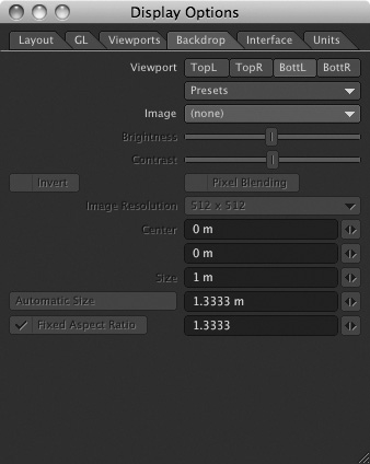
- Press d to open the Display Options panel. Click its Backdrop tab and then click the viewport button labeled BottL, which stands for bottom left (Figure 7.2).
Figure 7.2. Begin creating your titling package by using the Display Options panel to load a background image.
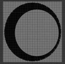
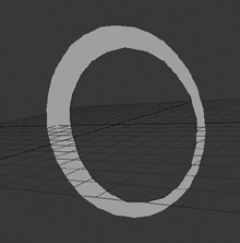
- For the Image selection in the panel, click Load Image and load OffsetCircle.jpg from the Chapter 7 folder on this book’s DVD (in the “3D_ContentImagesCH7” directory).
Here, you can import various images as background references to build from. This image is a circle within a circle that your client uses behind their main title font. They think it’s the next thing in brand identification. You just know it as a circle and consequently you’ll need to build this letter from the flat image.
Note
You can load an image in any format that LightWave accepts, which includes common formats such as JPEG, TIFF, TGA, PNG, and even PSD (Adobe Photoshop’s native file format). If you can’t seem to load an image, there’s a chance that your input-output plug-ins are not properly loaded. You can load them by going to the Utilities tab, selecting Edit Plug-ins, and then choosing Scan Directory. Point the scan to your installed LightWave plug-ins folder and click OK.
After the image is loaded, you’ll see it appear in the bottom left viewport, as shown in Figure 7.3. Telling LightWave to use BottL for the viewport means that the loaded image is placed in that particular view.
Figure 7.3. Loading the background image instantly shows it in the bottom left viewport.
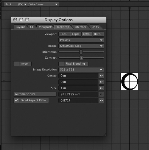
As you can see, the image is a bit smaller than the viewport. Creating in 3D is relative, and building a tiny logo or a large logo makes no difference when it comes to rendering. However, you’ll have an easier time flying a camera through the logo’s elements if you make it a bit larger than this default size. You might also notice some serious jagged edges around the image.
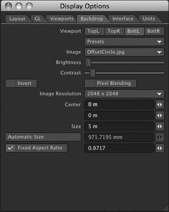
- In the Backdrop tab of the Display Options panel, change the Size to 5 m from the current 1 m.
- Change the Image Resolution setting to 2048 × 2048. This will allow you to see the image clear and sharp in the background.
- Bring the Brightness and Contrast settings down so that the backdrop image is not overpowering. When you create 3D models, your points and polygons might be hard (or impossible) to see if the backdrop image is excessively bright. Dim the backdrop until you can just see it as a reference. Click OK and then press a to fit the image into view. Figure 7.4 shows the results of the last three steps.
Figure 7.4. Increasing the size and resolution of the background image while decreasing the brightness and contrast gets the background image ready for modeling.
Note
Changing the Image Resolution setting in the Display Options panel has nothing to do with the actual resolution of the image or your 3D model. This is a display option only. LightWave allows display resolutions up to 4096 pixels.
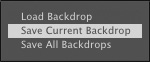
- Just in case you want to use this backdrop later, go ahead and save it. Click Presets in the Display Options panel’s Backdrop tab. Choose Save Current Backdrop (Figure 7.5) and give it a name such as OffsetCircle_bkd. Then when you want to use this again, just click Presets and Load Backdrop.
Figure 7.5. Save your backdrop to keep your settings for future use.
You’re now ready to begin creating the background blocks that your camera will fly through. Read on to create these elements.
Building Over Images
Using 2D images in your 3D modeling process is not only a good idea but also a smart way to create accurate models. The following technique is something you might find yourself using often in Modeler. You can use it for characters, automobiles, and, in this case, a logo. Designers like to create cool print design elements, which often create nightmares for animators to set in motion. However, by placing an image in the background as you’ve done in the previous steps, it’s quick and easy to build 3D elements right over the image.
Exercise 7.2. Using Backdrop Images for Modeling
- With the same backdrop image (the one you named OffsetCircle_bkd) loaded into the bottom left view, select the Pen tool from the Create tab. Then, click the Maximize Viewport button (Figure 7.6) at the upper-right corner of the viewport at bottom left. This expands your view to full screen. You’ll click it again later to return to a quad view.
Figure 7.6. Use the Maximize Viewport button to make the bottom left view full screen.

- Press . (period) a few times to zoom in to the view. Or click, hold, and drag on the Zoom tool at the top right of the viewport.
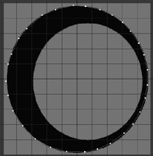
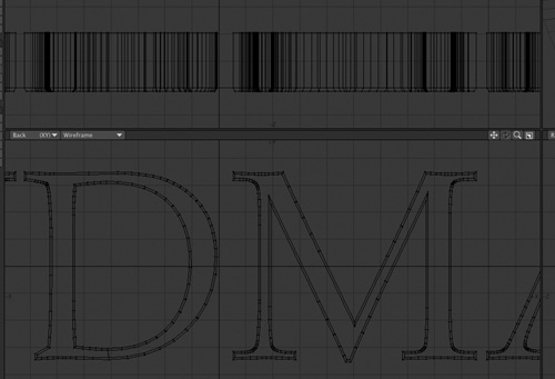
- With the Pen tool, click with the left mouse button to create roughly 30 points, evenly spaced. Click the points around the OffsetCircle image, as shown in Figure 7.7.
Figure 7.7. Use the Pen tool to click around the outline of the OffsetCircle image; each click creates a point in a polygon.
- The Pen tool instantly creates polygons by connecting points in succession as you click them. Click the Pen tool button again to deactivate the tool, and then click the button in the upper-right corner of the viewport to return to a quad view. You should see a shape in the Perspective view, similar to Figure 7.8.
Figure 7.8. Going back to a quad view shows the polygon you’ve created with the Pen tool.
Note
If you don’t see your model in Perspective view, its visible, editable surface, or surface normal, is probably facing away from you, toward the negative Z-axis. Press f to flip the normal forward.
- You have the first part of the logo built, so save it! Press Control+S to Save As, and save it as OffsetCircle. Each version you create from this point will be saved in increments as 001, 002, 003, and so on, using Shift+S.
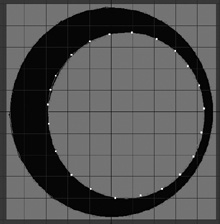
- Start working in a new layer. To do this, click an empty layer button in the top right of the interface. How do you know if it’s an empty layer? A layer that has geometry in it will have a small black dot. Pick a layer without the dot. In a new layer, also using the Pen tool, create about 22 evenly spaced points around the center space of OffsetCircle, as shown in Figure 7.9.
Figure 7.9. In a new layer, use the Pen tool to outline the center space in OffsetCircle.
- Save your work by pressing Shift+S. This will save your object as a new version with an incremental save. At this point you don’t need the background image, so press the d key, and in the Backdrop tab of the Display Options panel, set Image to None.
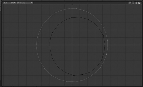
- You may have noticed that the object you created with the Pen tool looks kind of chunky. No worries; we’ll make it smooth and clean soon. For now, make sure that the larger circle is in the foreground layer and that the center circle is in a background layer, as shown in Figure 7.10. To place a layer in the background, simply click beneath the slash on the layer button.
Figure 7.10. Place the larger part of the circle object in a foreground layer and the center of the object in a background layer.
Note
A cool feature in LightWave is the ability to save in increments. After you save an object or scene for the first time, each time you press Shift+S afterward, you’ll save an incremental, numbered version of your project. For safety’s sake, get in the habit of using Shift+S to make incremental saves. That way, even if you make a mistake in an editing session, you’ll have the previous version as a backup.
- In the Construct tab, click the Drill tool (found in the Combine tool category), or press Shift+R to activate the tool and open the Template Drill panel.
The Drill tool allows you to “drill” a flat (2D) shape in one layer through one or more objects or shapes in different layer(s). (The Solid Drill tool works similarly but uses a 3D object as the “drill.”)
- In the Template Drill panel, click the Operation button marked Tunnel; then click the Axis button labeled Z (Figure 7.11). Click OK, and in a moment, you’ll see a nice hole in the center of the letter outline (Figure 7.12). Save your object!
Figure 7.11. Use the Drill tool’s Template Drill panel to create a hole in OffsetCircle.
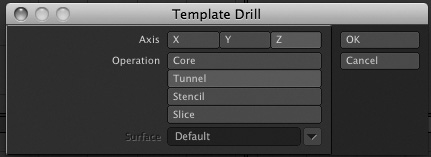
Figure 7.12. Using a Tunnel operation takes the background layer and cuts it through the foreground layer.
You built these objects using the Back view, which faces down the Z-axis; choosing Z aligns the drill operation along that axis. The Tunnel operation works as its name implies, using the background shape to bore a tunnel through the foreground shape. If you choose the Drill function, it performs just like the Template Drill, except that it’s used for objects that have more than two sides—that is, objects that have more dimensionality.
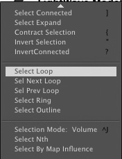
- Now you need to clean up the points and smooth them out a bit. Select two points on the outer edge, in sequence. Then, from the Select drop-down menu at the top left of the interface, choose Select Loop. This will select all the continuing points.
- Press Control+T to activate the Drag tool, and then click and drag on points to smooth them out, as shown in Figure 7.13.
Figure 7.13. Using the Drag tool, you can fine-tune the position of the object’s points.
- After you’ve positioned the points, save your work. Press the spacebar to deactivate the Drag tool, and then press / (forward slash) to deselect the points.
- If you’ve expanded the viewport, collapse the full-frame view by clicking the small icon in the top right of the viewport, returning you to a quad view.
Note
You easily turn the backdrop image on and off. Press d to open Display Options and on the Backdrop tab of the Display Options panel that opens, click the BottL viewport. Change Image to None to remove the image from the background of the viewports. The image is still loaded in Modeler, but it is not displayed. You may find yourself turning the background image on and off a few times while you are modeling, for visual reference. The backdrop image is not part of the model, but it’s still loaded in Modeler whether it’s visible or not. You can delete it for good from Modeler through the Image Editor.
Note
If you feel like your model needs a few more points in certain areas, you can first select the polygon (in Polygons mode) and then choose Add Points from the Subdivide category on the Multiply tab. Then, click with the Pen tool on the edge where you’d like to add a point.
This model is complete. This OffsetCircle object, looming large and semitransparent, will appear in the background of our final scene. You’ll call this object up later in Layout.
A few more things to know about using background images:
Note
If you would like to completely remove the image from Modeler, open the Image Editor, found on the top left of the Modeler interface. Select the image in the panel and press Delete on your keyboard.
Pen isn’t the only tool you can use to trace background images. Try the Sketch, Bezier, and Spline Draw tools; you can even use a background image as a reference when creating full 3D primitives or other objects. You’re using the Pen tool in this project because it creates polygons as soon as the points are laid down. If you’d used the Bezier tool, you’d have been creating curves, which would have required an extra step to “freeze” the curves into polygonal faces. Remember, polygons are necessary to apply a surface and render. The Bezier or Spline Draw options will create a smoother edge and are very useful for more detailed objects. Be sure to watch the video on the book’s DVD to learn how to use this tool over backdrop images (3D_GarageVideosCH1CH1_SplinesInModeler.mov).
Exercise 7.3. Creating Text in Modeler
When you create text in LightWave Modeler, you don’t always have to use a backdrop image.
- From the File menu, choose Close All Objects. This clears all geometry from LightWave Modeler. Then, press a to fit and reset the views.
- Press n to open the numeric panel. Then, on the Create tab, click the Text button (in the Text tool category) or press Shift+W to activate the tool dialog (Figure 7.14).
Figure 7.14. The Text tool active with the Numeric panel open, accessible from Modeler’s Create tab.
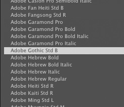
- Depending on the fonts on your system, the first font listing that appears might look sort of messed up. Certain system fonts won’t display properly in Modeler, but the majority of your installed fonts should work in LightWave. Click the Font drop-down list in the Numeric dialog box. You’ll see a list of your installed fonts, as shown in Figure 7.15.
Figure 7.15. The Font drop-down list in the Numeric dialog box lists your installed fonts.
- Pick an ordinary font, such as Book Antiqua. Any font will do, so if you don’t have this font, pick another, such as Arial. After you’ve chosen a font, click OK.
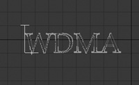
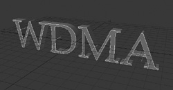
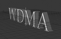
- Now, click the Text button, and then click in the Back viewport. You’ll see a cursor appear. Your keyboard is now a typewriter, and LightWave will not respond to keyboard equivalents. Type WDMA, the call letters for the Ablan Broadcast Network (Figure 7.16).
Figure 7.16. With the Text tool, you can add type to Modeler projects.
With the Text tool active, you can interactively adjust your font. You must do this before you deselect the tool, however. When you deselect the tool, the text object will become polygons, just like a box, a ball, or anything else you might create. You can then size, adjust, and change the shape as you like; however, turning the Text tool back on does not allow you to edit this text but rather creates new text. With the light blue text cursor still active, you can click and drag the top of the cursor to size the fonts. And you can click and drag the bottom vertical slash to adjust spacing between letters. Click and drag the lower-right corner of the cursor to position your text.
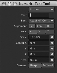
- In the Numeric panel, you can also add your text, rather than typing it out in the Modeler interface. You can also adjust the placement, alignment, and so on, as shown in Figure 7.17.
Figure 7.17. The Numeric panel for the Text tool allows you to change your fonts as well as set sizing options.
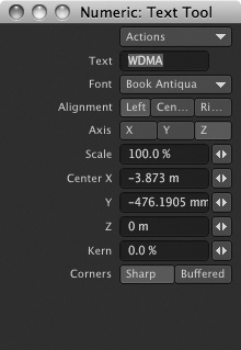
- If you like, you can change what text you’re typing right in the Numeric window as well. For now, set the Center X, Y, and Z values all to 0.
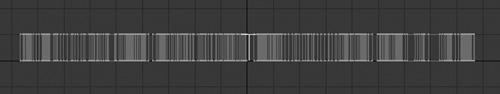
- Close the Numeric panel, and then click the Text tool to turn it off. Press a to fit the type you just created into the viewport. Figure 7.18 shows your soon-to-be-3D text.
Figure 7.18. Once your text is sized, close the Text tool and press a to fit your logo to view.

- Press Control+S to Save As, and save your font as WDMA_Flat. It’s a good idea to always save a flat version of type-based objects, in case you want to use them as an element in your animation, or perhaps need to rebuild the full logo. Press Control+S again and save the fonts as WDMA_3D. Now your flat version is saved and safe. Your newly saved version will be made into a 3D logo with a few more modeling tools.
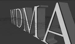
- Press F2 to center the text. This will move it to the 0 coordinate shared by the X, Y, and Z axes. On the Multiply tab, click the Extrude tool under the Extend category.
- In the Top view, click and drag to extrude the text about 200 mm on the Z-axis, as shown in Figure 7.19.
Figure 7.19. To create depth for your text, use the Extrude tool.
- Press the spacebar to turn off the Extrude tool. Press s to save.
Note
If you’re on a Mac and the F2 command doesn’t work, you can go to System Preferences and, under the Keyboard & Mouse tab, select the “Use all F1, F2, etc. keys as standard function keys” check box.
You now have 3D text! Congratulations! OK, it’s not that great-looking—but it will be! You need surfaces, and more importantly, bevels!
Exercise 7.4. Surfacing and Beveling Text in Modeler
LightWave Modeler offers you a lot of control. You can build just about anything your brain can conjure. But when it comes to 3D text, you really have no reference. If you build a lamp, or a house, or even a dog, you can use the real thing for comparison, but huge flying letterforms are scarce, so how do you determine what they should look like? As a start, take a look at what major networks are doing with 3D text. You’ll see a lot of letters with slick, gleaming surfaces and beveled edges—and that’s what you’ll be using in the logo you create.
- The process of applying bevels to type is easy, but there are a few things to do first. To get the most out of your 3D text in the final animation, you’ll want to apply separate surfaces to the faces and sides of the text and to the bevel you’ll soon create. To begin, press / to deselect all and then press q or click the Surface button at the bottom of the interface to open the Change Surface dialog box.
- You use the Change Surface dialog box to create surfaces. Enter WDMA_Sides in the Name field.
Despite its name, the Change Surface dialog box is used to create surfaces—identify them and assign colors to them. In case that’s not confusing enough, if you try to use it to change the color of an existing surface, you’ll see an error message that says “Control Is Disabled.” The reason for this is that when you create or identify a surface and assign it a color, there’s no going back—at least within the Change Surface dialog box. To change the surface’s color settings, you must use the Surface Editor. So again, Change Surface is not really about changing surfaces; it’s about creating them. However, if you assign a color in the Change Surface dialog box, that color will be attached to the selected geometry and show up in Layout when you render. You can, of course, change this value later in the Surface Editor.
Note
The Surface button at the bottom of the Modeler interface and the Surface Editor button at the top left of the interface do very different things. The Surface button at the bottom of the interface creates surfaces for your objects. The Surface Editor button at the top left of the interface changes your surface settings. Be sure to click the right button based on your task.
- After you’ve entered the name WDMA_Sides, turn off Make Default. Then click OK. Leaving Make Default on would mean that any new geometry you created in Modeler would be named WDMA_Sides. It’s good practice to have any nonsurfaced geometry assigned the generic name, “default,” so you can easily spot polygon regions that don’t have assigned surfaces. Don’t worry about setting a color just yet. Click OK to close the panel.
You just applied a surface name to your entire object. If no specific geometry is selected, actions you take in Modeler, including changing a surface, apply to your entire object. So why did you use “_Sides” in a name applied to all surfaces of every letter? Because it happens to be easier to select and rename the flat faces of the letters than it is to select all their side surfaces separately. If we select and rename the faces, everything left over will be assigned the correct “_Sides” surface name. Clever, huh? (In fact, before we name the letter surfaces, we’re going to use the same trick again to add and name a surface bevel.)
- Click the Polygons selection-mode button at the bottom of Modeler, or press the spacebar a few times to cycle to it. Then, select just the faces of the letters. You can do this quickly in the Perspective view by holding the Shift key and clicking each face (Figure 7.20).
Figure 7.20. Select just the faces of the letters.
- With the three letter-face polygons selected, click the Surface tool again (or press q), and type WDMA_Bevel in the Name field. Change the color slightly, perhaps to a light blue, to distinguish it from other parts of the object that are assigned surface names. You will change any colors assigned here in Layout; colors assigned in Modeler help you tell named surfaces apart. Click OK to close the Change Surface dialog box.
You’re probably wondering why you named the letter faces “WDMA_Bevel.” Good question. The Bevel tool adds new polygons to the current selection, and if a surface name has been assigned to that selection, it applies that name to the new geometry. So we’re temporarily naming the surface polygons “_Bevel” to apply that name to the new bevel geometry. When we’re done beveling, we’ll click those easy-to-select letter-face polygons one more time and finally give them their proper name.
- With the faces still selected, press b to call up the Bevel tool.
- Click and drag in any viewport to bevel the selection. Click and drag up to set the Shift, and click and drag left or right to change the Inset. You can also press the n key to open the Numeric panel. You’ll want to bevel your text to about 10 mm for the Shift, and 7 mm for the Inset (Figure 7.21). Think of the Shift property as pushing and pulling the selected geometry. Inset, then, is more like increasing or decreasing the size of the selected geometry.
Figure 7.21. Bevel the selected faces of the letters.
Note
Beveling can be awkward unless you pay close attention to your mouse movements. Concentrate first on forward-backward motion, which controls the bevel’s shift, and then focus on just left-right motion, which controls inset. When you randomly click and drag, it’s difficult to bevel accurately. Also, be sure not to bevel so much that the polygons cross over each other. You want only a slight bevel for added depth.
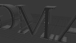
- If you look closely at the Perspective view (see Figure 7.21), you’ll see that the letter-face polygons are still selected, and the new bevel geometry is not; so press q again to open the Change Surface dialog box and change the surface name for the selection to WDMA_Face. Set a varying color to make sure that your surface name takes effect. This is not always necessary, and is merely an organizational step. You don’t need to assign a color when you create a surface name. And even if you have two surfaces that will have the same surface and texture later on, such as the sides and bevel of the text, it’s still a good idea to give each its own surface name. The reason for this is not only flexibility in surfacing, but also for smoothing. Certain surfaces will be smoother than others, even with the same color and reflections applied. Figure 7.22 shows the beveled and surfaced text.
Figure 7.22. With the newly beveled selection surfaced, you now have surfaces applied to the face, bevel, and sides of the text.
- Press the spacebar to turn off the Bevel tool. Then press / to deselect all geometry. Press Shift+S to save your work. Place the text object in a background layer by clicking beneath the slash in its layer button (Figure 7.23).
Figure 7.23. The text object is now in a background layer.
Since this element is being animated as one object, you can leave it all on the same layer. However, you might need to adjust the pivot point so that it can be animated properly.
Pivot Points in Modeler
Each layer in Modeler has its own X-Y-Z coordinate system, and when you create (or add) an object to a new layer, the object is centered by default on the layer’s origin point (coordinates 0, 0, 0). Modeler also uses that origin point as the object’s default pivot point, around which it will spin when rotated. This is fine for many things, but for precise animation, it can cause problems. This section shows you how to change objects’ pivot points.
Exercise 7.5. Setting New Pivot Points in Modeler
- Start by selecting the layer with your WDMA logo from the previous exercises. This model’s center is probably pretty close to the origin point. It was at this position, the default pivot point, when you pressed F2 earlier to center it. But since you’ve extruded and beveled it, the pivot is now at the face of the object. The pivot did not change—the object did.
The default pivot point for this object will not cause too many issues when animating in Layout; however, it could be a little more precise.
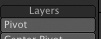
- Go to the View tab, and then select the Pivot tool under the Layers category, as shown in Figure 7.24.
Figure 7.24. Select the Pivot tool in the View tab to adjust pivots for any layer.
- When you activate the Pivot command, crosshairs appear in the viewports. Because you centered the flat object before you extruded, the WDMA letters look like they have a centered pivot if viewing from the Back view. However, upon closer inspection from the Top view, the pivot is at the face of the object, rather than the center. Move the pivot to the center of the object in the Top view (Figure 7.25). Be careful to pay attention to all views and move it on the Z-axis as well as the X-axis and Y-axis.
Figure 7.25. Manually move the pivot for Layer 1’s object.
- Save your work!
You can set the pivots for any of the layers in a project, but you do not have to turn off the Pivot tool to change layers. Just change to the new layer, adjust the new pivot, and away you go.
You’ve now created all the base animation elements for the logo treatment. The next steps are to build the main logo and create the subtext that you’ll animate as individual letters.
Importing EPS Files
LightWave also offers you the ability to import Adobe Illustrator files or EPS files. This is extremely handy for more complicated graphics designed out-of-house; as an animator, you’ll often be hired to animate a logo you haven’t designed. When you import a logo as an EPS file, Modeler automatically recognizes its outlines as spline curves you can scale, “freeze,” and surface. No tracing of a background image is required. This not only saves tons of time, it also allows you to create a more accurate 3D version of the original piece. To better explain how this feature works, there’s a cool tutorial video on the book’s DVD showing how to use this feature of Modeler.
Animating Text
Now that you have your base objects, it’s time to put it all together in Layout (Figure 7.26). Once in Layout, you can begin setting up your animation. First, you’ll set the placement, and then the lighting. After that’s in place, you’ll enhance the surfaces and set up camera moves. Are you ready? Good, then head to the book’s DVD for a great interactive movie on putting this full animation together. You’ll see how helpful LightWave’s VPR mode is for real-time previews right in Layout. The movie is called SceneSetup.mov.
Lighting, Motion, and Backgrounds
Until now, you’ve seen the basic setup before lighting is in place. What you do next is totally up to you. Many people put everything in motion first, then light, then render. Others light first, then animate. Here, we’ll do a little of everything!
Lighting is important in any scene, even a relatively simple logo animation. You’ll learn how to set up lighting for your scene and how to animate the text you’ve built—including the pivot points you changed. From there, you’ll create a cool moving background that provides an interesting environment for your scene. Included on this book’s DVD is a video showing you how to light this motion graphics scene. You’ll learn first-hand by seeing the exact setup with a clear explanation and visual results. Go watch the video now! It’s called MotionLighting.mov and it’s in the CH7 folder of the book’s DVD.
Once you have a good working animation and lighting setup, you can use additional lights for added interest. And what will really make this project stand out is the surfacing and background. We have much more to cover with LightWave, and it’s time to move on.
The Next Step
This chapter took you through some of the most basic LightWave operations. But the tools used, and the process in which you use them, are always the same no matter how complex your project might be. The next step, after you watch the videos on the book’s DVD, is to move on to Chapter 8 and learn about modeling products. As for this logo project, it’s up to you to use these steps and procedures to create your own logo for your company, for your client, or just for fun. In this chapter you’ve learned how to build over background images and use the text-creation tools. The videos for this chapter will extend your learning even further. And remember that as you model and texture, you also have to tweak. Tweak, tweak, tweak! There’s always more you can do with a scene, so take some time and do it.
Any little changes you make to your models and scenes are what give your animations that extra something. You’ll take your modeling and layout skills a step further in the next chapter.