Chapter One: Introduction to AutoCAD
Chapter Objectives
Explore CAD’s uses and benefits
Understand fundamental CAD concepts
Tour the AutoCAD user interface
Explore the different AutoCAD data input methods
Maximize AutoCAD’s InfoCenter and help system features
Introduction
This text is designed to allow you to “hit the ground running” using AutoCAD so that you can quickly start creating accurate technical drawings using accepted industry drafting standards. The next chapter (Chapter 2, Quick Start Tutorial) shows you the minimum you need to know in order to create and plot an AutoCAD drawing starting from scratch. These introductory concepts and techniques are then linked to detailed information about each topic so you can explore them at your own pace.
Before you can do any of that though, we need to cover some basics. This chapter introduces you to some fundamental CAD concepts and the AutoCAD user interface so you are prepared to hit the ground running in Chapter 2.
user interface: The commands and mechanisms the user interacts with to control a program’s operation and input data.
What Is CAD?
In a little over a generation’s time the methods used to create technical drawings have fundamentally changed from using pencil and paper to the use of computer-aided drafting, better known as CAD. The analog world of drafting boards, T squares, triangles, and even the romantic French curve (see Figure 1-1) has given way to the digital world of computers. No longer must you refill your mechanical pencil when you run out of lead, find your eraser when you make a mistake, or walk across the room to share a design with another person.
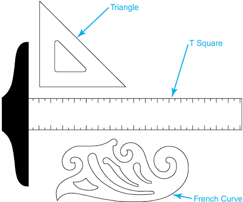
Figure 1-1 A T square, a triangle, and a French curve
Using CAD, you can draw something once and copy it hundreds, or even thousands, of times. Changing a design can be as simple as pushing a button. Drawings can be shared instantaneously across the room or even around the world. These and the other benefits of CAD include the following:
Increased productivity
Drawing content can be continuously reused.
Text and dimensions can be created and updated automatically.
Hatch and pattern fills can be placed with a single pick of the mouse.
Revising and editing drawings can be done quickly with minimum effort.
Parametric design tools allow you to constrain drawing objects based on your design intent.
parametric design: Design process that utilizes both variable and constrained dimensions that automatically update the drawing objects they are assigned to so that many different variations of a base design can be accurately represented.
Improved precision
Digital information is accurate to 14 decimal places.
Geometry is precisely located using the Cartesian coordinate system.
It is possible to snap to control points and features on existing drawing geometry to accurately locate drawing information.
Polar and object tracking features can be utilized for precise angular measurements.
Better collaboration
Drawings can be shared across a network (locally and globally).
Drawings can be referenced and updated in real time with notification.
Revisions and markups can be managed electronically via email, AutoCAD Web, AutoCAD Mobile, and Shared Views.

3D visualization and analysis (see Figure 1-2)
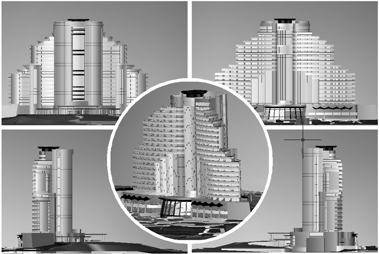
Figure 1-2 Sample 3D presentation drawing in AutoCAD
3D animations and walk-throughs can be easily generated to allow you and potential clients to visualize a design before it is constructed.
Interference checking can be done to ensure that parts do not run into each other before they are created.
Engineering calculations such as finite element analysis (FEA) and other structural calculations can be performed automatically.
Computer prototypes can be created and tested, eliminating the time and materials needed to manufacture a real-world prototype.
All these benefits are explored in this text, except for 3D visualization and analysis, which is beyond the scope of this text. The following chapters explain how to utilize the tools provided in AutoCAD to create and share the most accurate technical drawings in the quickest and most efficient manner. Using AutoCAD you will learn how to do the following:
Set up and lay out different types of AutoCAD 2D drawings using AutoCAD model space and paper space techniques.
Quickly create accurate 2D drawing information using AutoCAD’s precision drafting aids.
Edit and modify 2D drawing information in a productive fashion.
Annotate and dimension drawings using AutoCAD’s automated annotation and dimensioning features.
Create section views utilizing AutoCAD’s predefined and custom hatch and pattern fills.
Utilize and manage CAD standards including:
Layers
Linetypes
Text styles
Dimension styles
Coordinate drawing information with other team members using external reference files.
Create and manage symbol libraries using AutoCAD’s Blocks palette, DesignCenter, and tool palettes.
Output your drawings to different plotting devices and file formats with specific colors and lineweights.
Share your drawings online using AutoCAD Web, AutoCAD Mobile, and Shared Views.
![]()
![]()
Fundamental CAD Concepts
Because CAD-based drafting is a digital pursuit, some of the concepts that apply to its analog “on the board” cousin are a bit different. It is important that you are aware of and understand these concepts before we begin any drawing.
Drawing Actual Size
Board drafting requires that you select a scale before you begin a drawing. This is to ensure that whatever it is that you are drawing fits properly on the selected paper, or sheet size.
sheet size: The size of the paper on which a drawing is printed or plotted.
Large objects are scaled down so that you can see the complete design on the sheet while smaller objects are scaled up so that you can clearly discern finer details.
Unlike drawing on the board, CAD-based drafting does not require design information to be scaled as it is drawn. Everything is drawn actual size as it exists in the real world. This means that the layout of a floor plan that is 100′–0″ × 50′–0″ is actually drawn 100′–0″ long × 50′–0″ wide in AutoCAD. The scaling process occurs when the drawing is being set up to be printed or plotted to ensure that your drawing fits properly on the desired sheet size.
Using CAD, you have a theoretically infinite amount of space within your CAD drawing file to create your design. A drawing can be as large as our entire solar system or small enough to fit on the head of a pin. To help navigate within this infinite drawing space, AutoCAD provides a number of display tools that allow you to zoom and pan around a drawing similar to the zoom and pan functions found on a camera. This allows you to zoom up close to your drawing for detailed work or zoom out so that you can view the complete drawing.
Note
Annotation features like text and dimensions have their own unique scaling issues. You must typically scale annotation features so that they appear at the correct size in relation to the actual size drawing you are creating. For instance, 1/8″-high text appears as a tiny speck next to a 100′-0″-long wall. AutoCAD provides an Annotation Scale feature that helps automate the process. This feature is explained later in the “Annotation Scale” section on page 8.
The Cartesian Coordinate System
The primary means of locating information in an AutoCAD drawing is the Cartesian coordinate system. The Cartesian coordinate system is a grid-based system where points are represented by their x and y coordinate values separated by a comma as follows:
x,y
For example, a point located at x = 4 and y = 2 is represented as follows:
4,2
There is also a z coordinate, and we’ll talk about that later. For now, think of your computer screen as a 2D sheet of paper where the origin of the coordinate system (0,0) is in the lower left-hand corner of your screen as shown in Figure 1-3.
Positive x and y coordinate values are represented in the upper-right quadrant of the grid. Because it is easiest to work with positive coordinates exclusively, this is where most of your drawings will be created.
Right-Hand Rule
As alluded to earlier, the Cartesian coordinate system also has a z coordinate that is used to locate points in 3D space. The Z-axis runs perpendicular to the XY plane shown in Figure 1-3.

Figure 1-3 The Cartesian coordinate system
The easiest way to represent this concept is to rely on what is known as the right-hand rule—it’s as easy as 1-2-3.
right-hand rule: Easy-to-understand reference that can be used to determine the positive and negative direction of the X-, Y-, and Z-axes.
To start, clench your right hand into a fist with your palm facing toward you.
![]() Extend your thumb to the right.
Extend your thumb to the right.
![]() Uncurl your pointer finger so that it points straight up.
Uncurl your pointer finger so that it points straight up.
![]() Uncurl your middle finger so that it points toward you.
Uncurl your middle finger so that it points toward you.
Your hand should now look similar to the one shown in Figure 1-4. Using the right-hand rule, your thumb represents the positive X-axis, your pointer finger represents the positive Y-axis, and your middle finger represents the positive Z-axis.
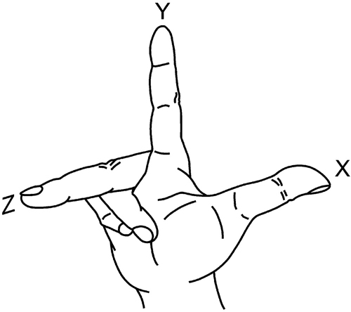
Figure 1-4 The right-hand rule
Your palm, and by extension your computer screen, represents the 2D XY plane where z = 0. Using this analogy, positive z values are toward you, or above the screen, while negative z values are away from you, or into the screen.
By default, the z coordinate value is set to 0. Because of this, there is no need to specify a z coordinate value when you locate 2D points. If the z coordinate is omitted, it is interpreted as 0. For instance, to locate a 2D point where x = 4 and y = 2, you can enter either of the following:
4,2,0 or 4,2
Of course, it makes sense to type the least amount possible, so all examples in this text rely on the shorthand version.
Tip
In AutoCAD, the default Cartesian coordinate system explained in this section is referred to as the world coordinate system, or WCS. It is possible to change the origin and orientation of the X-, Y-, and Z-axes for high-level drawing operations by creating your own temporary user coordinate system, or UCS. A temporary UCS can be quickly created and modified via the UCS icon in the lower-left corner of the AutoCAD drawing window, as explained later in this chapter. For more information, please consult the AutoCAD Help.
world coordinate system (WCS): The default coordinate system in AutoCAD upon which all objects and user coordinate systems are based.
user coordinate system (UCS): A user-defined variation of the world coordinate system.
Grid Units
In AutoCAD, one unit on the Cartesian coordinate grid system can represent whatever you want it to represent. A unit can be 1 inch, 1 foot, 1 millimeter, 1 meter, 1 nautical league, or even 1 parsec.
parsec: A unit of astronomical length.
Fortunately for us, the majority of the drafting and design world works in either inches (imperial) or millimeters (metric) where the following applies:
Imperial:
1 grid unit = 1 inch
Metric:
1 grid unit = 1 millimeter
There are of course exceptions to this unwritten rule, most notably in the civil design field. Because civil engineers work with drawings that cover large areas (parcel plans, highway plans, etc.), it is common for them to work in decimal feet or decimal meters where the following applies:
Imperial:
1 grid unit = 1 foot
Metric:
1 grid unit = 1 meter
Unless otherwise noted, most of the examples and drawing problems in this text will rely on 1 unit = 1 inch for imperial-type drawings and 1 unit = 1 millimeter for metric-type drawings.
Angle Measurement
By default, angles in AutoCAD are measured counterclockwise from 0°, which is due east, or right, on the positive X-axis as shown in Figure 1-5. Using this system of angle measurement, 90° is north, 180° is west, and 270° is south. It is possible to change the default 0° base angle to any of the other three compass directions, or a custom angle, as well as change the default angle measurement direction from counterclockwise to clockwise.
AutoCAD provides five different types of angle unit settings so you can enter angles in a format that applies to the type of work you are doing. Most architects and engineers prefer angles in decimal units (e.g., 45.00°) or degrees, minutes, and seconds (e.g., 45°00′00″), whereas those in the civil engineering world rely on surveyor units (e.g., N45°0′0″E).
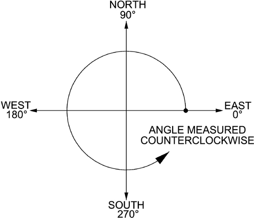
Figure 1-5 AutoCAD base angle and direction
Tip
You can also enter negative angle measurements when working in AutoCAD to input an angle that is measured in the clockwise direction. For example, an angle of 315° can also be entered as –45°.
Exercise 1-1 Using Cartesian Coordinates
![]() Using pencil and paper, lay out a Cartesian coordinate grid system similar to the one shown in Figure 1-3.
Using pencil and paper, lay out a Cartesian coordinate grid system similar to the one shown in Figure 1-3.
![]() Draw a line from the coordinate point (2,1) to the coordinate point (4,5).
Draw a line from the coordinate point (2,1) to the coordinate point (4,5).
![]() Draw a line from the origin (0,0) at an approximate angle of 135° to the edge of the grid.
Draw a line from the origin (0,0) at an approximate angle of 135° to the edge of the grid.
![]() Draw a line from the coordinate point (-2,-1) to the origin (0,0).
Draw a line from the coordinate point (-2,-1) to the origin (0,0).
![]() Draw a line from the origin at an approximate angle of -30° to the edge of the grid.
Draw a line from the origin at an approximate angle of -30° to the edge of the grid.
Annotation Scale
As mentioned earlier in the section “Drawing Actual Size,” the lines, circles, and other geometry that represent your design are drawn to their exact “real-world” specifications; the scaling occurs when you set your drawing up to plot on the desired sheet size.
To accommodate this scaling process, the size of annotation features such as text and dimensions must be adjusted accordingly when they are added to your drawing. This ensures that they print out at the correct size after they are scaled up or scaled down. Most organizations rely on drafting standards that define specific text heights, arrowhead sizes, and other annotation specifications so that drawings maintain a consistent appearance. The proper scaling of annotation features is very important so that drafting standards are always maintained.
As an example, annotation features on a drawing that is going to be scaled to 1/2 of its original size when it is printed must be scaled up by the reciprocal of 1/2, or 2 times, when they are created. With this in mind, if your drafting standards require that text print out 1/80 high, you must apply the following formula:
1/8″ × 2 = 1/4″-high text
When the drawing is then plotted, the 1/4″-high text is scaled by 1/2 and prints out at the correct standard text height of 1/8″. See Figure 1-6. In this example, 2 is considered the scale factor. The scale factor is the reciprocal of the plotted scale. Calculating the scale factor in the preceding example is easy because the plotted scale is a simple ratio of 1:2. It’s obvious that the reciprocal of 1:2 is 2.
scale factor: Multiplier that determines the size of annotation features when a drawing is plotted or printed.
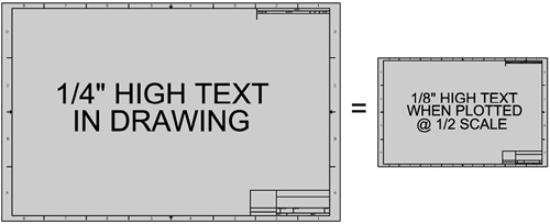
Figure 1-6 1/4″ text scaled to 1/8″ at plot time
Calculating, and applying, scale factors for all the different annotation-type objects can be a tedious, time-consuming process. Fortunately, it is possible to automate the process using the AutoCAD Annotation Scale feature. Annotation objects such as text and dimensions have an annotative property that, when enabled, automatically scales the objects according to the scale selected. The annotation scale is controlled via an easily accessible list of the same standard drawing scales found in Appendix A. Annotation objects can even have more than one annotation scale so that they are displayed at the correct size on multiple different scale drawings!
Note
There are other things in a drawing that are affected by the annotation scale besides just text and dimensions. Special linetype definitions and hatch patterns can also be affected.
Object Properties
In AutoCAD, the lines, circles, text, dimensions, and just about everything else that make up a drawing are commonly referred to as objects. All these drawing objects have properties associated with them that control their appearance and behavior. Some properties are unique to a particular type of object, especially properties that relate to an object’s geometry. For example, a circle object has a radius, whereas text has a height. Other object properties are shared by all the objects in a drawing. These general object properties are introduced in the following sections.
Layers. Before the advent of CAD, drafters and designers coordinated their drawings by physically overlaying them on top of each other. The paper, known as vellum, was translucent so that as you layered each drawing on top of the previous one, the drawing(s) underneath were still visible. This allowed the drafters and designers to compare the work on each individual drawing and coordinate them as a complete system. See Figure 1-7.

Figure 1-7 Overlay drafting
Flash forward to the digital world of the twenty-first century. Using CAD, this concept of physically “layering” multiple drawings one on top of another has morphed into the ability to separate distinct drawing information using named layers. Typically, the name of the layer reflects the type of information that resides on it. For instance, a layer named WALL might contain drawing information that relates to the walls of a floor plan, while a layer named DOOR might contain the lines and arcs that represent the doors. In fact, numerous standard layer-naming conventions and guidelines have been created that allow people to share CAD drawings and understand what type of drawing information resides on each layer.
CAD-based layers provide much more functionality and control than their analog vellum-based cousins. Layers in CAD can be turned off and on so that you can create multiple views of your drawing information. For instance, text and dimensions can be put on their own unique layers so that they can be turned off when you want to concentrate on your design. Similar drawing information can be grouped on specific layers so that you can coordinate between different disciplines. The electrical wiring might be located on a layer named ELEC while the mechanical heating ductwork might be located on a layer named HVAC. Basically, layers give your drawings a level of intelligence that allows you to indicate what objects in a CAD drawing represent in the real world.
Besides controlling the visibility of drawing information, layers also can be used to control the color, linetype, lineweight, and transparency of an object. You can even use layers to determine whether an object is plotted or not.
Colors
Colors can serve multiple purposes in an AutoCAD drawing:
![]() They separate drawing information so that it is easily identifiable on the computer screen.
They separate drawing information so that it is easily identifiable on the computer screen.
![]() They allow printing and plotting with specific line thicknesses.
They allow printing and plotting with specific line thicknesses.
![]() They allow color output on color printing and plotting devices.
They allow color output on color printing and plotting devices.
The first use of colors is fairly obvious. One of the easiest ways to differentiate between different drawing information on the computer screen is by using color. You might set up your drawing so that all the walls are green, the doors are blue, and the text is yellow. This color coding makes your drawing easier to comprehend and work with.
The second use of colors might seem a bit obscure to many new AutoCAD users—to control line thicknesses when plotting. This use of colors was introduced very early on in AutoCAD’s life as one of the only means of plotting a drawing with varying line thicknesses, a necessity for most organizations. This color-based approach to controlling lineweights is still in use today because of the time and effort necessary to update legacy systems. For this reason, it is a good idea to at least have a basic understanding of how the color-based approach works.
Without getting into too much detail, color-based plotting is based on the fact that each color in AutoCAD is associated with an integer value. This relationship is referred to as the AutoCAD Color Index, or ACI. The ACI consists of 255 colors numbered from 1 to 255, with the first seven colors represented as follows:
1 = Red
2 = Yellow
3 = Green
4 = Cyan
5 = Blue
6 = Magenta
7 = White
In the early days, plotting was done on pen plotters using numbered ink pens with varying pen tip sizes that created different line thicknesses. The numbered plotter pens were associated with the information in the drawing via the object’s color. For example, red drawing objects plot with pen #1 because the color red = 1 in AutoCAD’s Color Index. This color–to–plot pen relationship is referred to as a plotter’s “pen mapping.” Thankfully, this antiquated approach to controlling plotter pens is quickly being heaped on the trash bin of history as the much simpler approach of using AutoCAD’s lineweight property becomes more popular.
Note
There is another approach to controlling line thicknesses on a plot using plot styles. It is possible to assign a unique plot style directly to an object that will control the object’s appearance on the printed page.
plot style: A collection of property settings that is applied when the drawing is plotted to control the appearance of the drawing objects on the printed drawing.
Linetypes
Manually drawing objects with different linetypes on the board is a very tedious process, if not an art form. A mechanical pencil and a scale must be utilized so that you can accurately measure out the dashes, dots, and/or gaps over the distance of a line.
Fortunately, AutoCAD provides more than 40 different predefined linetypes that can be applied directly to your line work with a click of a button. Figure 1-8 shows examples of linetypes that come with AutoCAD.

Figure 1-8 Examples of default AutoCAD linetypes
Tip
The dashes, dots, and gaps that make up a linetype definition are also affected by the scale factor described earlier. Their size must be adjusted to accommodate the plot scale in the same fashion as the other annotation features in order for them to print out at the right size.
Lineweights
In AutoCAD, the term lineweight is used to refer to a line’s thickness. Different drafting standards dictate how line thicknesses should be applied in technical drawings.
Drawing different line thicknesses on the board requires that you use different pencils with different lead thicknesses. AutoCAD provides graphical lineweights that you can assign to your line work, which allows you to see different line thicknesses on the screen before you plot your drawing. There are more than 20 different lineweights available in both imperial (inches) and metric (millimeters) format.
Transparency
It is possible to make objects transparent in AutoCAD so that you can see through them and view objects that are below. The level of transparency can be adjusted up or down so that you can control the visibility of the objects. By default the transparency level is set to 0, which means all objects are opaque, and you cannot see through them.
Controlling Object Properties
The common approach to controlling the general object properties discussed in the previous sections is to set the desired object property active, or current, before drawing an object. An object assumes the current object properties when it is drawn. This does not mean you cannot change an object’s properties after it is drawn. In fact, a multitude of tools in AutoCAD help you accomplish this.
Exercise 1-2 Researching CAD Layer Guidelines
![]() Using the Internet, search for websites with information about the “AIA layer guidelines.” (Note: AIA is the abbreviation for the American Institute of Architects.)
Using the Internet, search for websites with information about the “AIA layer guidelines.” (Note: AIA is the abbreviation for the American Institute of Architects.)
![]() Describe the AIA layer-naming scheme and how it is organized.
Describe the AIA layer-naming scheme and how it is organized.
![]() Find an example of at least one other layer standard or guideline.
Find an example of at least one other layer standard or guideline.
Model Space and Paper Space
AutoCAD has two distinct drawing environments: model space and paper space. Model space is the 3D drawing environment, described earlier in “The Cartesian Coordinate System” section, that is used for the drawing model, or 3D representation of your design. Model space contains most of the line work, text, and dimensions that make up a drawing.
model: The geometry (lines, circles, etc.) created in a drawing that defines the object or objects drawn.
Paper space is the 2D environment used for laying out different views of the model space information on a standard sheet size and scale for plotting purposes. This 2D page setup is known as a layout in AutoCAD and typically consists of one or more views of your drawing along with a border and title block.
layout: 2D page setup created in paper space that represents the paper size and what the drawing will look like when it is printed.
Metaphorically speaking, an AutoCAD paper space layout can be thought of as a 2D sheet of paper that hovers over your 3D model space drawing. Scaled views are created by cutting holes in the paper so you can see the 3D drawing model. See Figure 1-9.
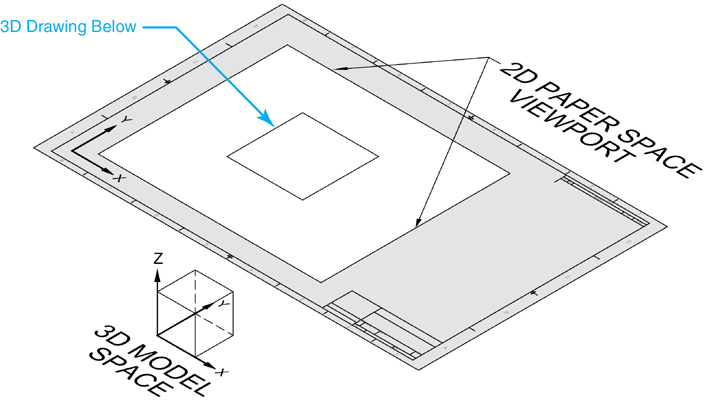
Figure 1-9 Model space and paper space
Tip
It is possible to have multiple layouts in an AutoCAD drawing. Each layout can be a different sheet size and can also contain multiple scaled views.
AutoCAD File Types. By default, a drawing in AutoCAD is saved as a file with a .DWG file extension. For example, a floor plan drawing might be saved with the file name
Floor Plan.dwg
A file name can be up to 256 characters long and can include most of the alphanumeric characters, including spaces ( ), dashes (-), and underscores (_). A file name may not include any of the following special characters:
/|:" *?><<
Windows is not case sensitive, so you can mix uppercase and lowercase letters when naming a file and Windows will not distinguish between them. For instance, the file name in the example above:
Floor Plan.dwg
is the same as
FLOOR PLAN.DWG
Proper file naming, and by extension, proper file management, is one of the most important aspects of using CAD effectively.
Tip
By default, every time you save a drawing in AutoCAD, a backup file with the .BAK file extension is created. The backup file is the last saved version of the .DWG drawing file. This allows you to always have the last saved version of your drawing to “roll back” to if something happens to the current .DWG file.
Some of the other common file types and extensions used by AutoCAD are listed in the following table.
AutoCAD File Types |
|
|---|---|
File Extension |
Description |
AC$ |
Temporary AutoCAD file. Created automatically by AutoCAD |
BAK |
AutoCAD drawing backup file. Created automatically when a drawing is saved |
DWG |
AutoCAD drawing file |
DWF/DWFx |
AutoCAD Design Web Format file |
DWL |
AutoCAD drawing lock file. Created automatically by AutoCAD |
DWS |
AutoCAD Drawing Standards file |
DWT |
AutoCAD drawing template |
DXB |
Binary AutoCAD design exchange format file |
DXF |
ASCII AutoCAD design exchange format file |
PLT |
AutoCAD plot file |
SV$ |
AutoCAD automatic save file |
If you are unsure of a file type, consult the AutoCAD Help.
A First Look at AutoCAD
AutoCAD is one of the more complex software applications. There are myriad commands, menus, palettes, and dialog boxes. The following sections explain all these features and how they work so you can get the most out of the AutoCAD user interface.
The Start Tab
![]()
The first thing you see when you start AutoCAD is the Start Tab shown in Figure 1-10. The Start Tab displays as a file tab when you launch AutoCAD and remains displayed throughout your AutoCAD session.
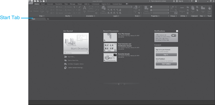
Figure 1-10 The Start Tab
The Start Tab provides an easy way to access sample files, recent documents, templates, notifications, and to connect to the online community via A360. It’s divided into three columns: Get Started, Recent Documents, Notifications, and Connect.
In the Get Started column shown in Figure 1-11, you can either use the Start Drawing tool to quickly begin a new drawing from a default template or choose from a list of available drawing templates organized by groups. The last template you use becomes the new default. Other tools enable you to open existing drawings and sheet sets, get more templates online, and explore sample drawings.
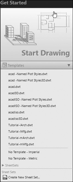
Figure 1-11 The Get Started column
In the Recent Documents column shown in Figure 1-12 you can view and open your recent drawings. Drawings can be pinned so that they remain on the list. The icons at the bottom of the column allow you to switch between thumbnail view, thumbnail and text view, or just text view.

Figure 1-12 The Recent Documents column
In the right column, under Notifications, are all notifications regarding product updates, hardware acceleration, trial periods, and about the offline help file information. A notification badge is displayed when there are two or more new notifications.
Under Connect, you can sign in to your Autodesk account to access online services and provide feedback about AutoCAD directly to Autodesk.
The AutoCAD User Interface
![]()
Because AutoCAD is a program for drawing, the focal point is the drawing window. This is where you create your drawing. Everything else surrounding the drawing window helps you accomplish this task. The ribbons, panels, menus, and other tools that you interact with to create your drawings are collectively referred to as the user interface. These interface items are controlled, in turn, using what are referred to as AutoCAD workspaces.
workspace: A named configuration of menus and palettes that are grouped and organized so that you can work in a custom, task-oriented drawing environment.
The user interface for the default AutoCAD Drafting & Annotation workspace is shown in Figure 1-13.
The major interface features provided in the Drafting & Annotation workspace are as follows:
Application Menu Clicking on the Application Menu button displays a menu of commonly used AutoCAD file tools and drawing utilities and provides quick access to open or recently opened drawings. It’s also possible to access the Options dialog box and exit AutoCAD via buttons at the bottom of the menu
Quick Access Toolbar Provides easy access to all the most commonly used tools such as New, Open, Save, Save As…, Open from Web, Save to Web, Plot, Undo, and Redo.
Ribbon Provides easy access to most of the AutoCAD tools via task-specific tabs and panels. Each tab has multiple panels containing related tools. Panels with a black arrow on the bottom center can be expanded to access additional tools.
In-Canvas Viewport Control Allows you to change viewport settings, views, and visual styles in the AutoCAD drawing window below.
Drawing Window The theoretically infinite space where you create the lines, circles, text, and so on that make up your drawing using the Cartesian coordinate system explained earlier.
File Tabs Provide an easy way for you to access all the open drawings in AutoCAD. A file tab typically displays the full name of the file. Clicking the plus sign (+) on the right end of the file tabs opens the Start Tab so you can start a new drawing.
Mouse Crosshairs Used for locating points and selecting objects when working in a drawing. The crosshairs switch back to a pointer when the mouse is outside of the drawing window.
ViewCube Allows you to easily switch between different 3D views in your drawing using your mouse.
Navigation Bar Provides easy access to most commonly used navigation tools so you can control what is displayed on your screen.
UCS Icon Represents the current user coordinate system (UCS); by default, this is set to the world coordinate system (WCS), where the X-axis is aligned horizontally and the Y-axis is aligned vertically.
Command Line Window Provides access to the AutoCAD command line where it is possible to enter commands and their options, as well as display the history of previously entered commands. The command line window is also where AutoCAD displays many default command settings and other important messages.
Model/Layout Tabs The Model and Layout tabs allow you to quickly switch between model space and different paper space layouts.
Status Bar Minidashboard for AutoCAD that does many things, including interactively displaying the current mouse crosshairs coordinate location, toggling different drawing tools on and off, setting the scale factor, managing workspaces, and more.
InfoCenter Allows you to search for useful information about a topic by entering keywords or phrases, provides access to the Autodesk App Store, the online destination for application downloads, AutoCAD product updates, and AutoCAD Help.
Workspaces
Most of the features that define the user interface for a particular setup (ribbons, panels, menus) are managed using AutoCAD workspaces.
The Drafting & Annotation workspace is the default current workspace when you start AutoCAD. The Drafting & Annotation workspace, shown in Figure 1-13, turns off all of AutoCAD’s 3D tools and features so that you have quick and easy access to all of the 2D tools required for this text.
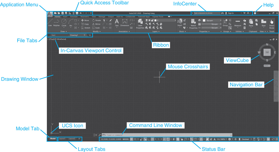
Figure 1-13 The default AutoCAD user interface
AutoCAD comes with other standard workspaces that you can switch to at any time by selecting the Workspace Switching button on the right side of the AutoCAD status bar at the bottom of the AutoCAD drawing window, as shown in Figure 1-14.
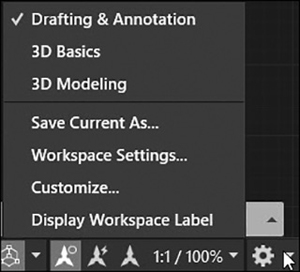
Figure 1-14 Workspace Switching button on the status bar
The 3D Basics workspace is intended for users who are new to 3D by combining the most commonly used 3D modeling commands.
The 3D Modeling workspace turns off most of the 2D AutoCAD tools and replaces them with AutoCAD’s advanced 3D tools and features.
Note
The Drafting & Annotation workspace is the default workspace used for all of the exercises in this text. If it is not your current workspace, you should set it current now.
Quick Access Toolbar
![]()
The Quick Access toolbar shown in Figure 1-15 provides quick and easy access to the following commonly used AutoCAD tools:

Figure 1-15 Quick Access toolbar
New Creates a new drawing file based on the selected AutoCAD template file
Open Opens an existing AutoCAD drawing or template file
Save Saves the drawing in its current location if it has been saved previously. Otherwise, performs a “Save As” the first time so that the drawing file name and location can be specified
Save As… Displays the Save As dialog box so you can rename the drawing and/or change the file type to an earlier version of AutoCAD
Open from Web & Mobile Opens an existing drawing file from your online Autodesk Web & Mobile Account
Save to Web & Mobile Saves a copy of the current drawing to your Autodesk Web & Mobile Account
Plot Prints a drawing to the specified printing device or file type with the settings specified
Undo Allows you to undo one or more recent commands
Redo Allows you to reverse the effect of the last undo command
Clicking on the down arrow on the right side of the Quick Access toolbar displays the flyout menu shown in Figure 1-16 so you can add or remove common tools.

Figure 1-16 Quick Access toolbar flyout menu
Selecting More Commands… from the menu allows you to add additional commands via the Customize User Interface (CUI) dialog box.
In addition, the Show Menu Bar option allows you to turn on the pull-down menus traditionally located across the top in previous releases of AutoCAD. The Show Below the Ribbon option moves the Quick Access toolbar below the ribbon.
Right-clicking on the Quick Access toolbar displays the shortcut menu shown in Figure 1-17 that provides some of the same options as the flyout menu discussed above plus a few more. Using the right-click menu you can remove tools, add separators between tools, add additional commands via the Customize User Interface (CUI) dialog box, or move the toolbar below the ribbon.
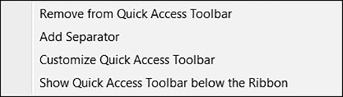
Figure 1-17 Quick Access toolbar shortcut menu
Application Menu
Clicking on the big A button at the top left of the AutoCAD window displays the application menu shown in Figure 1-18.
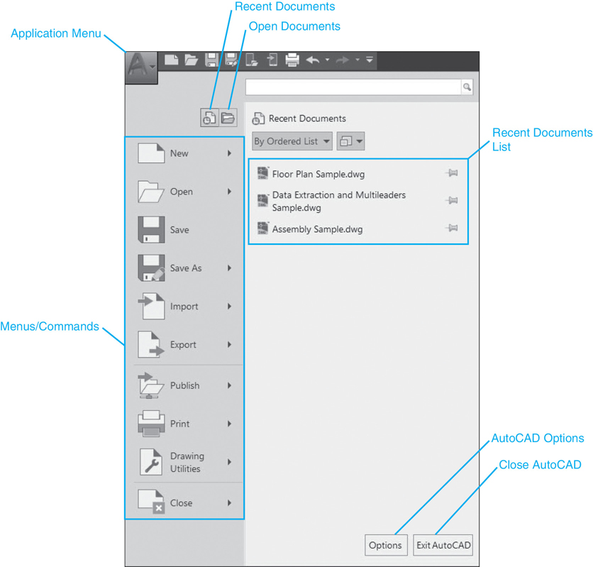
Figure 1-18 Displaying the application menu
The application menu provides easy access to commonly used AutoCAD file tools and drawing utilities via a menu that is split into a left pane and a right pane so that placing your mouse pointer over the main menu item on the left automatically displays a submenu list of related tools on the right, as shown in Figure 1-19. If the submenu list is longer than can be displayed, you must use the arrow at the bottom of the right pane to scroll down so that you see the desired menu item.
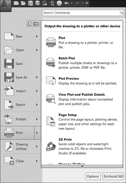
Figure 1-19 The Print submenu
The search tool at the top right of the application menu allows you to search through all of the AutoCAD tools by specifying key terms. For example, if you start typing L-I-N-E in the search field, AutoCAD dynamically displays all the tools that include the word LINE, as shown in Figure 1-20. Click on an item in the list to initiate the associated AutoCAD tool.

Figure 1-20 Using the Application Menu search tool
Additional Time-Saving Application Menu Features. In addition to easy access to AutoCAD file tools and drawing utilities, it is also possible to view and access recently opened drawings or drawings that are currently open in other windows via the two buttons at the top of the application menu shown in Figure 1-18. For example, selecting the Recent Documents button displays a list of recently opened drawings, as shown in Figure 1-21.

Figure 1-21 Viewing recently opened drawings
By default, recent drawings are displayed in an ordered list of when they were last accessed. It is possible to group drawings by access date, size, or file type via the By Ordered List drop-down menu at the top left.
The View icon button directly to the right of the By Ordered List drop-down menu allows you to change the file display from icons to small, medium, or large preview images. Additionally, briefly hovering the cursor over the drawing name displays a preview image. If you do not move your cursor for a few split seconds, the preview is expanded to include other important file information as shown in Figure 1-22.

Figure 1-22 Displaying a preview image
AutoCAD Options. The Options button at the bottom right of the application menu displays the AutoCAD Options dialog box shown in Figure 1-23. The Options dialog box is your one-stop shop for controlling and maintaining most AutoCAD features and settings such as the color of different window elements, size of the cursor crosshairs, default print settings, and so on. Because it is accessed so often, it is located on the application menu for easy access. It can also be found at the bottom of most AutoCAD right-click shortcut menus discussed later in the chapter. You’ll want to remember this because accessing and using the Options dialog box is discussed often throughout the rest of the text.
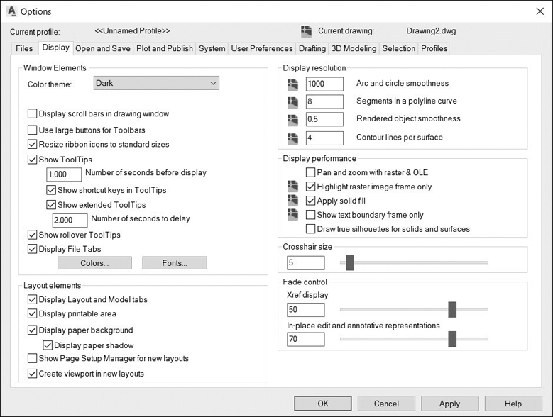
Figure 1-23 The AutoCAD Options dialog box
Ribbon
![]()
The ribbon at the top of the AutoCAD window shown in Figure 1-24 provides quick and easy access to the most used AutoCAD tools and features via a variety of task-specific tabs and panels.

Figure 1-24 Ribbon
Each task-specific tab contains multiple panels that, in turn, contain related tools. In addition, panels with a black arrow next to the panel name can be expanded to access additional tools as shown in Figure 1-25.

Figure 1-25 The Draw ribbon panel with additional tools displayed
The default tab is the Home tab shown in Figure 1-24, which provides access to the most commonly used AutoCAD tools and features. The other tabs and their associated tools are as follows:
Insert Tools for working with blocks and block attributes, external references, point clouds, importing different file formats, managing drawing data, and inserting content
Annotate Tools for creating and modifying text and dimensions, creating leader notes and tables, marking up and revising drawings, and managing annotation scaling features
Parametric Tools for establishing and maintaining geometric constraints and dimensional relationships
View Tools for controlling the display of different AutoCAD interface features, managing viewports, turning different palettes on and off, and viewing and switching between multiple open drawings
Manage Tools for recording and playing command macros, customizing the AutoCAD interface, loading and running custom programs, managing CAD standards, and cleaning up drawings
Output Tools for plotting and publishing drawings and creating DWF/PDF files
Add-ins Provides access to the Autodesk App Manager, which allows you to view, update, uninstall, and get help on all of the Autodesk Apps downloaded from the Autodesk App store
Collaborate Provides access to Shared Views, which allows you to share views online and DWG Compare for comparing drawing versions
Featured Apps Provides easy access to the Autodesk App store where you can browse and download AutoCAD apps; includes a selection of featured apps that you can select and download directly from the Featured Apps tab without browsing through the entire Autodesk App site
Express Tools Variety of productivity tools that allow you to perform a number of different useful tasks and operations. Technically not supported by Autodesk because they were originally developed by outside users
Clicking on another tab swaps the current tools displayed with the set of tools selected so that a minimum amount of space is required for the tools you need and the drawing space is always maximized. In Figure 1-26 the Annotate tab has been selected so that the tools for adding text, dimensions, and other annotation features are now displayed.

Figure 1-26 Annotate tab of the ribbon
Tip
The small arrows pointing down on the right side of some panel title bars shown in Figure 1-26 are buttons that when clicked display the style dialog box for the corresponding panel. For instance, clicking on the down arrow button on the right side of the Text panel displays the Text Style dialog box.
Controlling the Ribbon Display. The ribbon has a number of different display features and options. Right-clicking on a panel tab displays the shortcut menu shown in Figure 1-27.
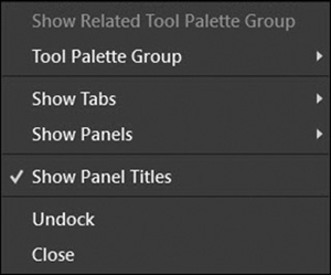
Figure 1-27 The ribbon right-click menu
Using the right-click menu, you can turn different ribbon tabs and panels on and off by selecting them from their corresponding submenus. You can turn off all the panel titles at the bottom of the ribbon by deselecting the Show Panel Titles option.
The arrow buttons on the right side of the Express Tools tab shown in Figure 1-28 allow you to maximize the size of the drawing display window even further.

Figure 1-28 The ribbon Minimize menu
Clicking on the down arrow on the far right displays the menu shown in Figure 1-28 that allows you to minimize the ribbon using three different options.
Selecting the Minimize to Panel Buttons option collapses all the panels so that only the ribbon tabs and button representations are displayed. Placing your mouse pointer over a button temporarily displays the panel so you can select the desired tool similar to Figure 1-29. The panel then collapses back to the button-only display when you move your mouse pointer back over the drawing window.

Figure 1-29 Single ribbon panel temporarily displayed
Selecting the Minimize to Panel Titles option collapses all the panels so that only the ribbon tabs and panel titles are displayed. Placing your mouse pointer over a panel title temporarily displays the panel so that you can select the desired tool similar to Figure 1-29. The panel then collapses back to the title-only display when you move your mouse pointer back over the drawing window.
Selecting the Minimize to Tabs option collapses all the panels and their titles so that all that is visible are the ribbon tabs across the top. You must click on the tab to display its respective ribbon temporarily while you choose the desired tool. The ribbon then disappears when you move your cursor back over the drawing window.
Tip
Clicking on the arrow button to the immediate left of the down arrow that displays the Minimize options menu discussed previously (see Figure 1-28) allows you to cycle between the full ribbon and the current Minimize option.
You can reorganize ribbon tabs, or panels within individual tabs, by simply dragging and dropping them to a different location on the ribbon using your mouse. It is even possible to drag panels completely off the ribbon and create separate, what are called “sticky,” panels, which float above your drawing window.
Tooltips
You may have already noticed that information about a tool automatically appears directly at your mouse pointer if you hover the pointer over a tool for a short period of time. This useful feature is commonly referred to as a tooltip. The tooltip for the Line tool is shown in Figure 1-30.
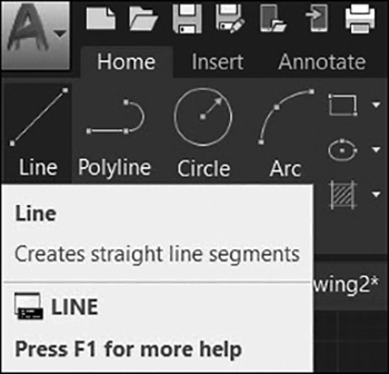
Figure 1-30 Line tooltip
The best part is that if you hover the mouse pointer for a split second more without moving, the tooltip expands to display additional information if it is available, sometimes even including helpful graphics, as shown in Figure 1-31.

Figure 1-31 Line tooltip with additional information displayed
In addition, pressing the <F1> function key on your keyboard will display the complete AutoCAD online help topic for the current tool for even more detailed information. The AutoCAD online help system is discussed in detail at the end of this chapter.
The Command Line Window
The command line window provides access to the AutoCAD command line (see Figure 1-32). The AutoCAD command line allows you to enter AutoCAD commands by typing them on the keyboard. It is also one of the ways AutoCAD communicates with you via command prompts and messages.

Figure 1-32 The command line window
By default, the command line is displayed in a semitransparent single row that floats above the bottom of the AutoCAD drawing window. Directly above the command line is a command prompt history that is dynamically updated so you can keep track of all of the previous command prompts as you work through a command.
Tip
The default number of lines displayed in the command prompt history is three. You can change the number of lines displayed by clicking on the wrench icon on the left of the command line window shown in Figure 1-33 and selecting the Lines of Prompt History option.
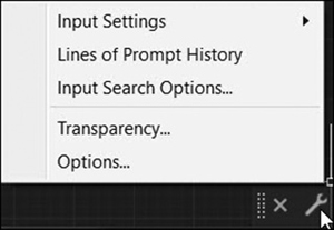
Figure 1-33 Command line options menu
Note
Command line transparency can be controlled by clicking on the wrench icon on the left of the command line shown in Figure 1-33 and selecting Transparency… from the flyout menu to display the Transparency dialog box.
The command line window provides a number of other customizable features and options:
AutoComplete Automatically completes commands or system variables on the command line as you enter them (see Figure 1-34)
system variable: A named setting maintained by AutoCAD that controls an aspect of a drawing or the drawing environment.
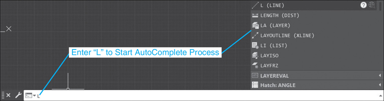
Figure 1-34 The Autocomplete list
AutoCorrect If you mistype a command, AutoCAD autocorrects it with the most relevant and valid AutoCAD command
Adaptive Suggestions As you use AutoCAD, the order of commands in the suggestion list adapts to your own usage habits
Synonym Suggestions The command line has a built-in synonym list that will return a command if a match is found (see Figure 1-35)

Figure 1-35 The Synonym Suggestions list
Internet Search You can quickly search for more information on a command or system variable in a suggestion list by moving the cursor over the command or system variable in the list and choosing the Help or Internet icon (see Figure 1-36)

Figure 1-36 Internet Search
Content Insertion You can use the command line to access layers, blocks, hatch patterns/gradients, text styles, dimension styles, and visual styles and insert them directly from a suggestion list (see Figure 1-37)
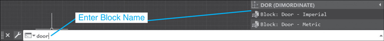
Figure 1-37 Content Insertion
Tip
To make a suggestion list easier to navigate, commands, system variables, and other content are organized into expandable categories. You can either expand a category to see the results or press the <Tab> key and cycle through each category.
You can control the command line features and options by clicking on the wrench icon to display the Input Settings cascade menu shown in Figure 1-38. All of the options are turned on by default.

Figure 1-38 Input Settings
Selecting Input Search Options… from the command line configuration menu displays the Input Search Options dialog box shown in Figure 1-39 so you can further refine the command line options and features.
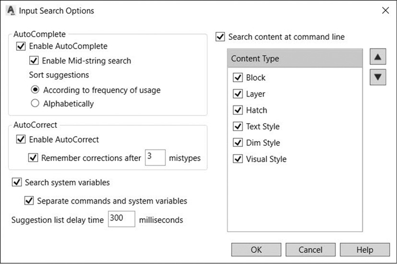
Figure 1-39 Input Search Options
Entering Commands via the Keyboard. AutoCAD commands can be entered by typing them at the keyboard. For instance, the command to draw a line can be entered by typing Line<Enter> at the command line as follows:
Line<Enter>
AutoCAD commands are not case sensitive so you can enter any combination of uppercase and lowercase characters with the same result.
Tip
When AutoCAD is awaiting a command, an icon that looks like ″>_″ is displayed on the left of the command line along with the prompt to “Type a command”. When a command is active, the ″>_″ icon is replaced with the command’s icon along with the command name to let you know you are currently in a command.
Tip
Clicking on the down arrow icon on the left side of the command line shown in Figure 1-40 displays a flyout menu of the most recently used commands so you can quickly reenter a recent command by simply clicking on it.

Figure 1-40 Command history
Most commands can also be abbreviated to speed up their entry. The abbreviated version of a command is known as a command alias.
command alias: An abbreviated definition of a command name that enables you to enter commands faster at the keyboard by typing the first one or two letters of the command.
Typically, the command alias is the first one or two letters of the full command. The abbreviation for the LINE command is L:
L<Enter>
Tip
Hitting the <Enter> key or the spacebar when no command has been typed will reenter the last command. This is a time-saving device that allows you to enter the same command repeatedly. For this reason, the most productive way to work in AutoCAD is to group like operations together. This allows you to “stay in the command” without losing focus jumping around to other ribbons, panels, and commands. Always try to focus on one operation.
Entering Command Options at the Command Line. Many commands have options that the user can select by entering a designated response using the keyboard. Options are always displayed as a list in square brackets with clickable options displayed in blue and separated by spaces. The ZOOM command prompts you with the following options at the command line:
Specify corner of window, enter a scale factor (nX or nXP), or
[All Center Dynamic Extents Previous Scale Window Object] <real time>:
Note
The spacebar at the bottom of the keyboard works exactly the same as the <Enter> key in AutoCAD. Because it is larger, easier, and faster to get to, some people prefer using it over the <Enter> key. The spacebar is especially helpful when used as described in the preceding TIP to repeat commands!
Options can be selected either by clicking on them with your mouse or by entering them at the keyboard. If you enter the option via the keyboard, you can either type in the complete option keyword or, more simply, type in whatever letter is displayed in blue and capitalized in the option keyword. For example, to use the ZOOM command with the Window option, you can enter either Window or W in response to the ZOOM command prompt. The Previous option can be entered as P, the Extents option as E, and so on. Obviously, typing a shortened abbreviation is faster than typing the complete word so the liberal use of abbreviations is suggested.
Default Command Options. Sometimes a command will display a default option indicated with the option displayed between angle brackets. The default can be selected by simply hitting the <Enter> key. For instance, the default option for the ZOOM command is always <real time>. This means if you simply hit the <Enter> key in response to the ZOOM options prompt, you will be automatically placed in the Zoom Realtime mode.
AutoCAD remembers some command options so you don’t have to type them the next time you use the command. For example, the default radius for a circle always reflects the radius you entered the last time you created a circle. The following is a CIRCLE command prompt with the default set to 2.0000 units.
Specify radius of circle or [Diameter] <2.0000>: <Enter>
If you are creating another circle with a radius of 2.0000 units, hit the <Enter> key, and voilà!
Canceling a Command with the <Esc> Key. The <Esc> key at the top left of the keyboard cancels, or aborts, an active command. It is probably the most used keyboard key in AutoCAD! When you hit the <Esc> key, the current command is immediately aborted.
Hitting the <Esc> key will also “unselect” any objects that are currently selected in the drawing window.
The Command History. AutoCAD remembers every command entered in an AutoCAD session from the time you start AutoCAD up until the very last command you enter. This is known as the command history. You can display the command history by selecting the up arrow on the right side of the command line as shown in Figure 1-41 or by hitting the <F2> key. The command history is distinguished from the active command line using a gray background color. You can scroll backward and forward through the command history using the arrow keys on your keyboard. The up arrow scrolls backward through the command history, whereas the down arrow scrolls forward. You can scroll backward or forward to any command in the history and run it again by hitting the <Enter> key.

Figure 1-41 Command line history
You can change the color used for the command history background color and other command line window features via the Drawing Window Colors dialog box, which can be displayed by selecting the Colors… button on the Display tab of the Options dialog box.
Resizing, Moving, and Docking the Command Line Window. The command line can be resized, moved, and even docked at the top or bottom of the AutoCAD window. To resize the command line window so you can see more lines of text, place your mouse pointer over the top or bottom edge of the command line window so that the pointer switches into a double arrow. Hold down your left mouse button and drag up or down, and the window size changes accordingly.
The command line can also be moved by clicking on the grab bar on the left side and dragging it with your mouse. If you move the command line near an edge of the drawing window, it will snap to the edge. If you want to place the window near the edge without snapping, simply hold down the <Ctrl> key while moving it.
You can dock the command line at either the top or the bottom of the AutoCAD drawing window by dragging it using the grab bar to the top or the bottom.
Turning the Command Line Window Off. The command line window can be turned off by simply selecting the X on the command line grab bar on the left. It can be turned back on using the <Ctrl>+9 keyboard combination. When the command line is turned off, commands can still be entered with the keyboard using dynamic input, which is explained in the next section.
The Full Text Window. It is possible to switch to a larger separate command line window known as the Text window by pressing <Ctrl>+<F2> function key at the top of your keyboard. Pressing <Ctrl>+<F2> once will display the Text window, as shown in Figure 1-42. The Text window can be minimized, maximized, and resized using standard Windows techniques. Pressing <Ctrl>+<F2> again toggles the window off.
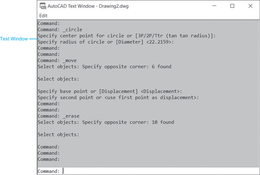
Figure 1-42 The Text window
You’ll notice that there is an Edit pull-down menu in the Text window. Selecting it displays the menu shown in Figure 1-43.

Figure 1-43 Text window menu
This menu gives you even more command line options. You can run recent commands, select old commands and paste them to the command line to repeat them, and even copy the complete command history.
Dynamic Input
Dynamic input is a set of related input display features that allows you to enter information near the mouse cursor so you can focus on your drawing instead of constantly switching focus to the command line.
Viewing and Entering Data Near the Mouse Cursor. When the Dynamic Input feature is turned on, you input data at the cursor by toggling between different input fields. Figure 1-44 shows the Pointer Input feature, which allows you to enter x and y coordinate values right at the cursor. Coordinates are entered by typing the x coordinate value and the y coordinate value separated by a comma. When you enter the comma, the x value is locked, and input changes to the y value. You can also use the <Tab> key to switch between the x and y values. Hitting <Enter> accepts both values.

Figure 1-44 Viewing and entering data near the mouse cursor
Dynamic input also provides a Dimension Input feature that displays temporary dimensions as you draw that you can dynamically update to create objects parametrically. The values that you enter in the dimension input fields are the values used to create the object. See Figure 1-45.
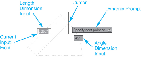
Figure 1-45 Using dynamic dimensions to create a line
parametric: Automated creation of a drawing based on a given set of dimensions referred to as parameters.
The <Tab> key allows you to toggle between the different input fields. For instance, pressing the <Tab> key in the example shown in Figure 1-46 switches the input field from the dynamic length dimension to the dynamic angle dimension as shown in Figure 1-46.
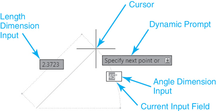
Figure 1-46 Using the <Tab> key to toggle through input fields
Selecting Command Options Near the Mouse Cursor. Earlier we saw that command options can be specified by selecting them with your mouse or by typing all or part of them at the AutoCAD command line. By using the Dynamic Prompt feature you can also select command options using either your mouse or the keyboard. If you press the down arrow key on your keyboard, a list of the valid command options is displayed near the cursor as shown in Figure 1-47. You can either use your mouse to select the desired option or navigate up and down the list using the arrow keys on your keyboard. Using this method, you must press <Enter> when the desired option is indicated.

Figure 1-47 Selecting ZOOM command options using dynamic input
Tip
The cursor provides contextual feedback by displaying badges that reflect the state of many common operations. An Inspection badge is displayed when using inquiry tools such as Distance, Radius, Angle, Area, Volume, List, and ID. A rotation badge is displayed when specifying the angle of rotation during a Rotate operation. Relevant badges are displayed when using Zoom or Erase or the editing commands including COPY, MOVE, and SCALE.
Right-Click Shortcut Menus
AutoCAD is chock-full of right-click shortcut menus. They’re everywhere. If you’re ever in doubt, right-click with your mouse, and you are bound to find something useful. Some of the more prominent right-click menus are introduced next.
If you right-click with your mouse over the drawing window when no drawing objects are selected, the Default shortcut menu shown in Figure 1-48 is displayed.
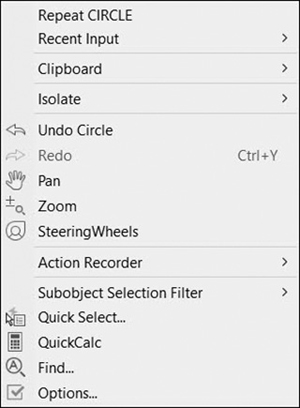
Figure 1-48 Default shortcut menu
If you right-click when objects are selected in the drawing window, the Edit shortcut menu shown in Figure 1-49 is displayed so that you can modify the selected object(s).
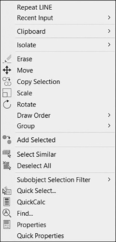
Figure 1-49 Edit shortcut menu
If you right-click when a command is active, the Command shortcut menu shown in Figure 1-50 is displayed, providing access to different command options, and so on.

Figure 1-50 Command shortcut menu
Accessing Recent Input. It is possible to access recent command input using the keyboard up and down arrow keys or the right-click shortcut menu shown in Figure 1-51.
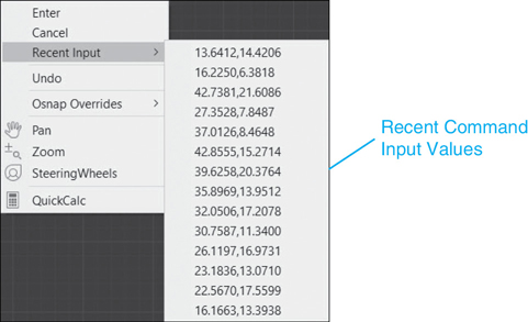
Figure 1-51 Accessing recent input
The Recent Input feature is a time-saving feature that allows you to recall recently entered data values so you don’t have to type them again regardless of whether the values were entered via the keyboard in the first place. AutoCAD remembers all the input values from all the input methods.
Tip
If you use the right-click menu to list the recent input when no command is active, AutoCAD will display a list of recently used commands.
Status Bar
![]()
The status bar is located at the very bottom of the AutoCAD window shown earlier in Figure 1-13.
The status bar provides quick access to some of the most commonly used drawing tools. Using the status bar, you can easily toggle settings such as grid, snap, polar tracking, and object snap (see Figure 1-52).

Figure 1-52 The status bar
Note
By default, not all of the status bar tools are displayed. The Customization menu on the far right side allows you to choose what tools to display. In addition, the tools that are displayed might change depending on the current workspace and whether the Model tab or a Layout tab is current.
The status bar provides a number of different features:
Drawing Coordinates. Displays the coordinates of the cursor. Right-click to choose coordinate type to display:
Relative Displays coordinates relative to the point you most recently specified
Absolute Displays coordinates relative to the current UCS
Geographic Displays coordinates relative to the geographic coordinate system specified for the drawing
Specific Updates coordinates only when you specify points
Model or Paper Space. These buttons switches the drawing environment to the last active paper space layout if you are currently in model space. Select it so it switches to PAPER. If you are in paper space and select the button and change it to MODEL, the last viewport will become active so you can work “through” the viewport (same as double-clicking on a viewport).
Drawing Tools. The drawing tool buttons allow you to toggle different drawing tools on and off interactively as you work in your drawing. The majority of the tools are explained in detail in Chapter 5.
Many drawing tool buttons have their own unique right-click menu that allows you to control that tool’s specific settings and features.
Annotation Scale Tools. As mentioned earlier in the “Fundamental CAD Concepts” section, it is possible to automate the process of creating annotation objects such as text and dimensions at the correct size for the final plotted drawing scale using the Annotation Scale feature located on the right side of the status bar (see Figure 1-52). Clicking on the Annotation Scale button displays a menu with a list of predefined scales, as shown in Figure 1-53.
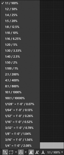
Figure 1-53 The Annotation Scale menu
When annotation objects that have their annotative property enabled are added to the drawing, they will automatically scale up or down by the current annotation scale so that you do not have to scale them manually.
The two buttons to the left of the Annotation Scale allow you to add and view annotation objects at multiple scales so that it is possible to reduce redundant annotation information in your drawings.
In the past, drawings that had multiple scales had to have separate copies of all the annotation objects such as text and dimensions at different scales to account for each drawing scale factor. Typically, different scale representations of the annotation objects were located on separate layers so that they could be turned on and off for each scale as needed. It was a very complex process, and because it required redundant information, it was prone to errors and omissions.
Chapters 11 through 14 discuss in detail how to utilize the AutoCAD Annotation Scale features to add and manage different annotation objects.
Workspace Switching. This button allows you to switch between AutoCAD’s default workspaces, save a custom workspace, control workspace settings, and customize workspaces.
Workspaces allow you to save and restore the on/off status and positions of the ribbon, palettes, and menus so that you can set up different work environments for different tasks. For instance, you might set up a dimensioning environment that has all the AutoCAD dimension tools turned on while most of the other AutoCAD tools are turned off so that you can focus strictly on the task of dimensioning.
To save your own custom workspace, you first set up the AutoCAD environment in the way you wish to save it by turning on and off the features you want and positioning them accordingly. Click on the Workspace Switching button and select Save Current As… from the menu and then enter a workspace name.
To restore a saved workspace, click on the Workspace Switching button and select it from the list.
The Workplace Settings… menu item allows you to control which workspaces are displayed, the menu order, and whether workspace changes are automatically saved when switching workspaces.
Annotation Monitor. This button toggles on and off annotation monitoring, which provides feedback regarding the status of annotation objects that are associated with views, sections, and details that have been automatically created using AutoCAD’s advanced 3D model documentation tools.
Drawing Units. This button allows you to toggle between Architectural, Decimal, Engineering, Fractional and Scientific unit settings.
Quick Properties. This button toggles on and off the Quick Properties palette that displays when objects are selected so you can quickly change object properties. Right-click on the button to control the Quick Properties settings.
Lock User Interface. This button locks the location and size of toolbars, panels and dockable windows such as the Properties palette.
Isolate Objects. The Isolate Objects button displays a small menu that allows you to control object visibility independent from layer visibility using the following two options:
Isolate Objects Only selected objects remain visible in the drawing. All other objects are hidden.
Hide Objects Selected objects are hidden. All other objects are visible. Objects that are isolated or hidden can be restored at any time using the End Object Isolation tool that is added to the Object Display menu after objects have been selected.
Hardware Acceleration. Right-click to control settings that affect display performance when working in 2D and 3D. These settings include hardware acceleration, effects available through your system’s graphics card, and software performance settings.
Status Tray. On the right of the status bar is the status tray. The status tray dynamically updates with different icons that are used for notification features and different task-specific settings depending on what you’re doing. For instance, after a plot is complete a notification balloon is displayed in the status tray with information about whether the plot was successful, as shown in Figure 1-54.
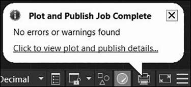
Figure 1-54 Plot status notification balloon
Clean Screen Toggle. This toggle temporarily turns off most of AutoCAD’s graphical interface features, such as the ribbon and palettes, and maximizes your drawing area so that you have more room to draw. Clicking on the Clean Screen toggle again turns everything back on. The Clean Screen toggle is explained in detail in Chapter 3.
Customization Menu. This menu shown in Figure 1-55 allows you to toggle different status bar control features on and off.

Figure 1-55 The Customization menu
In-Canvas Viewport Control
The in-canvas viewport control located in the upper-left corner of the AutoCAD drawing window is comprised of the three separate shortcut menus shown in Figures 1-56 through 1-58. These menus allow you to quickly change viewport settings, views, and visual styles directly in the drawing window.

Figure 1-56 The in-canvas viewport control

Figure 1-57
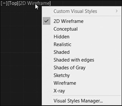
Figure 1-58
The first menu on the left, which is displayed when you click on the “-” symbol, is the most useful in the 2D world because it controls the ViewCube and navigation bar displays explained in the following sections. You can ignore the other menus when working strictly in 2D drawings.
Tip
Turn the in-canvas viewport control on and off via the Display the Viewport Controls check box on the bottom left of the 3D Modeling tab of the Options dialog box.
ViewCube
The ViewCube tool, shown in Figure 1-59 at its default position in the upper-right corner of the AutoCAD drawing window, is a clickable and draggable interface that you can use to switch between standard and isometric views of your model.
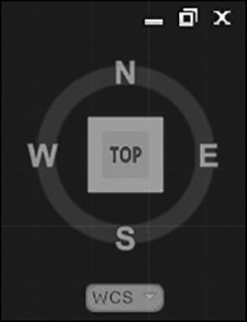
Figure 1-59 The ViewCube tool
The ViewCube tool provides visual feedback about the current viewpoint of the drawing model as view changes occur. When your mouse pointer is positioned over the ViewCube tool, it becomes active so that it is possible to drag or click and switch to one of the available preset views, roll the current view 90° clockwise or counterclockwise, or switch to an isometric view of the model.
Considering that the ViewCube tool is more of an advanced 3D tool, it might be best to turn it off for now. The easiest way to do that is via the shortcut menu shown earlier in which is displayed when you select the “-” symbol on the in-canvas viewport control. It is also possible to turn the ViewCube tool on and off from the 3D Modeling tab of the Options dialog box. To turn off the ViewCube tool in the 2D drawing environment, uncheck the 2D Wireframe visual style check box under the Display the ViewCube section at the bottom left of the dialog box shown in Figure 1-60.
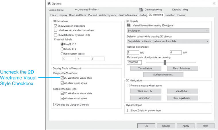
Figure 1-60 Turning off the ViewCube tool in the Options dialog box
Tip
Remember that it is possible to quickly display the Options dialog box by right-clicking and selecting Options… from the bottom of most shortcut menus.
Navigation Bar
The navigation bar shown in Figure 1-61 provides quick and easy access to frequently used navigation tools including 3D SteeringWheels, Pan, Zoom, 3D Orbit, and ShowMotion.
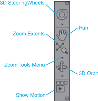
Figure 1-61 The navigation bar
The Pan and Zoom tools are of most interest because they allow you to navigate the 2D drawing display so that you can view all of the information in the drawing at the scale necessary to do your work. The other tools are primarily for 3D use and are beyond the scope of this text. Consult AutoCAD Help if you want more information about the 3D tools.
Clicking on the Pan tool changes your mouse pointer to a hand icon that indicates that you can click and hold your left mouse button down to drag the drawing around the drawing display. You can press <Enter> or <Esc> to close the Pan tool. Right-clicking will display a handy shortcut menu that also allows you to exit or to switch to a few different Zoom tools that are useful.
The Zoom tool defaults to Zoom Extents, which will zoom in or out in order to fill the drawing display with the extents, or outermost reaches, of the drawing. Selecting the down arrow at the bottom of the Zoom Extents tool displays a complete menu of different Zoom tools, as shown in Figure 1-62.
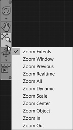
Figure 1-62 The different Zoom tools
The main Zoom tools are introduced in Chapter 2, and all of the Zoom tools are explained in detail in Chapter 3 so that you can get around and navigate your drawings.
Tip
The easiest way to turn the navigation bar on and off is by selecting the ″-″ symbol on the in-canvas viewport control in the upper left of the drawing window to display the shortcut menu and deselect the Navigation Bar option. Alternatively, you can also use the NAVBAR command. To turn the navigation bar on or off, type NAVBAR<Enter> and then specify On or Off.
Dialog Boxes
Dialog box is the term used to describe any of the graphical windows displayed in response to a command that allows you to select and specify various command options. AutoCAD has many different dialog boxes. Selecting the Open tool from the Quick Access toolbar displays the Select File dialog box shown in Figure 1-63. This dialog box is common to many file-related commands. The common file dialog boxes work very similarly to Windows Explorer.
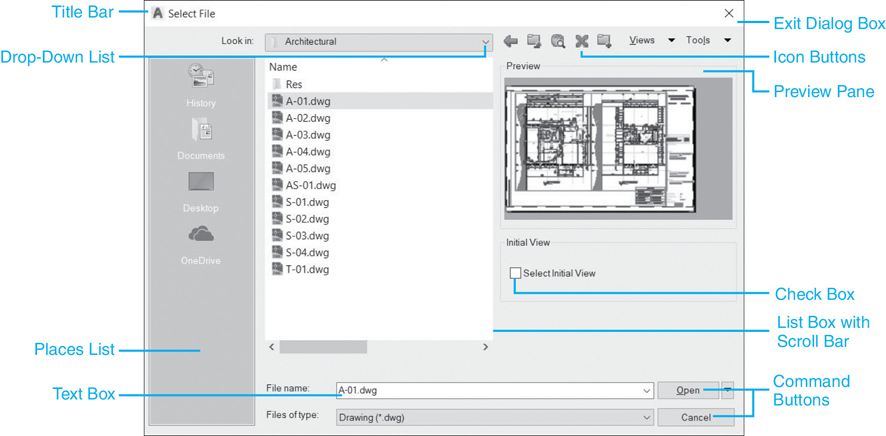
Figure 1-63 Select File dialog box
Note
The default size of some dialog boxes is larger. It is now possible to resize other dialog boxes while maintaining these size changes the next time you launch AutoCAD.
Tip
The common file dialog boxes contain a right-click shortcut menu that provides the same commands and options found in Windows Explorer so that you can perform different file operations without leaving AutoCAD.
Palettes
Palettes are separate windows that provide additional AutoCAD functionality. The cool thing is that palettes can be continuously displayed so that you can work between the palette and your drawing, like an artist creating a painting. Because of this capability, palettes have a special feature called Auto-hide that can be set to automatically hide a palette when you are not using it, freeing up your drawing window for actual drawing.
The easiest way to turn palettes on and off is via the Palettes panel on the View tab of the ribbon shown in Figure 1-64.

Figure 1-64 Palettes panel buttons
Tool Palettes. Tool palettes provide easy access to commands, hatch patterns, and blocks via a series of tabbed palettes as shown in Figure 1-65. To switch to a palette, select the corresponding tab. You can select a tool palette item either by clicking on its icon or by dragging an icon into your drawing window.
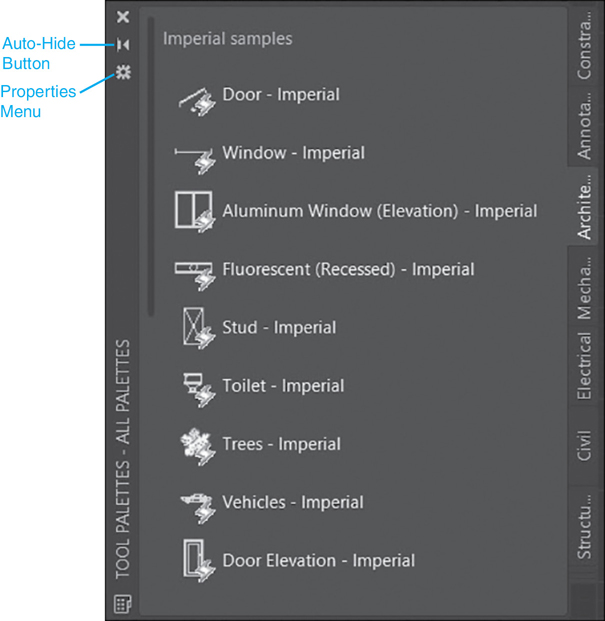
Figure 1-65 Tool palettes
Tool palettes are meant to be customized, allowing you to add and organize your own commands, blocks, and hatch patterns. The default content is provided as a sample of what you can do. Creating custom tool palettes with your own blocks, hatch patterns, and commands is discussed later in the text.
Properties Palette. The Properties palette is your one-stop shop for managing the drawing object properties explained earlier. In Figure 1-66, the properties of a line are displayed in the Properties palette.

Figure 1-66 The Properties palette
Sheet Set Manager Palette. The Sheet Set Manager is used to create and manage AutoCAD sheet sets. For further information about the Sheet Set Manager, please consult AutoCAD Help.
sheet set: An organized and named collection of sheets created from multiple AutoCAD drawing files.
Auto-hide Feature. As mentioned, it is possible to “hide” a palette using the Auto-hide feature. When Auto-hide is on, the palette collapses so only the title bar is visible when your mouse is not over the palette. When you move your mouse back over the palette’s title bar, the palette expands so it is completely visible again.
Note
The Auto-hide feature can be used when a palette is docked by selecting the “-” button on the right side of the title bar.
The easiest way to turn the Auto-hide feature on and off is by clicking on the Auto-hide arrow icon on the palette’s title bar, as shown in Figure 1-66. Auto-hide can also be turned on and off using the Palette Properties shortcut menu explained in the next section.
Palette Properties. Each of the palettes introduced previously has similar properties that are controlled by clicking on the Properties icon on the palette’s title bar, as shown in Figure 1-66. Selecting the Properties icon on any palette displays a Properties shortcut menu similar to the one shown in Figure 1-67. Using the Palette Properties menu, you can turn the Auto-hide feature on and off and indicate whether a palette can be docked or not. A palette can be docked on either the left or right side of your drawing window. The Properties palette is shown docked on the right side of the screen in Figure 1-68.

Figure 1-67 Palette Properties menu
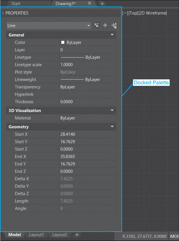
Figure 1-68 Docking the Properties palette
The Anchor Left and Anchor Right options on the Palette Properties menu allow you to dock a palette on the left or right of the AutoCAD window with the Auto-hide feature on so that the palette is reduced to a thin strip represented by the palette title bar, as shown in Figure 1-69.

Figure 1-69 Properties palette anchored on the right with Auto-hide turned on
Placing your mouse pointer over the title bar displays the palette temporarily so that you can make any changes or updates. Turning the Auto-hide feature off when a palette is anchored will change it back to the docked mode shown earlier.
Transparency. It is possible to make palettes transparent so that you can see the drawing under, or through, the palette. The Transparency… menu item on the Palette Properties menu displays the Transparency dialog box shown in Figure 1-70.

Figure 1-70 The Transparency dialog box
The slider bar at the top in the General area controls the overall transparency of palettes. By default, palettes are set to 100% opacity so that you cannot see through them. Sliding the bar to the left makes the palettes more transparent.
By default, palettes that are transparent will change back to 100% opacity when your mouse pointer is above them so that you can see them. The slider bar in the middle in the Rollover area allows you to change it so the palette will stay transparent.
It is possible to apply any changes to all the palettes in AutoCAD by selecting the Apply these settings to all palettes check box at the bottom of the dialog box. To make all palettes 100% opaque and turn off transparency throughout AutoCAD, select the Disable all window transparency (global) check box.
Keyboard Commands
AutoCAD has a number of other keyboard commands besides the <Esc> key that cancels a command in progress and the <F2> function key that displays the Text window. Keyboard commands provide quick access to a number of commands and options.
Function Keys. Function keys are the keys at the top of most keyboards that are labeled <F1> through <F12>. The most famous function key is <F1>, which is used to display the Help window in almost every Windows program. We have already seen the <F2> key, which toggles the AutoCAD Text window on and off. The other function keys also work as toggles, mostly as alternates for the drafting aids found on the AutoCAD status bar. A complete list of function keys and their associated functions is provided in the following table.
AutoCAD Function Keys |
|
|---|---|
Function Key |
Description |
<F1> |
AutoCAD online help system |
<F2> |
Command history toggle |
<F3> |
Object Snap toggle |
<F4> |
Tablet Mode toggle |
<F5> |
Isoplane toggle |
<F6> |
Dynamic UCS toggle |
<F7> |
Grid Mode toggle |
<F8> |
Ortho Mode toggle |
<F9> |
Snap Mode toggle |
<F10> |
Polar Tracking toggle |
<F11> |
Object Snap Tracking toggle |
<F12> |
Dynamic Input toggle |
Control Key Combinations. Control key combinations are created by holding down the <Ctrl> key, typically located on the bottom row of your keyboard, while selecting some other key on the keyboard. For example, holding down the <Ctrl> key and selecting the C key at the same time copies information to the Windows Clipboard. A control key combination is typically expressed as <Ctrl>+Key. The preceding copy example is expressed as <Ctrl>+C.
Like the function keys, control key combinations are provided as a quick alternative to commands found elsewhere in AutoCAD. Some control key combinations are common to many Windows programs, whereas some are exclusive to AutoCAD. A complete list is provided in the following table.
AutoCAD Control Key Combinations |
|
|---|---|
Combination |
Description |
<Ctrl>+A |
Select all |
<Ctrl>+B |
Snap Mode toggle |
<Ctrl>+C |
COPYCLIP command |
<Ctrl>+D |
Dynamic UCS command |
<Ctrl>+E |
Isoplane toggle |
<Ctrl>+F |
Osnap toggle |
<Ctrl>+G |
Grid Mode toggle |
<Ctrl>+H |
Pickstyle toggle |
<Ctrl>+I |
Coordinate Display toggle |
<Ctrl>+J |
Repeats last command |
<Ctrl>+K |
HYPERLINK command |
<Ctrl>+L |
Ortho Mode toggle |
<Ctrl>+M |
Repeats last command |
<Ctrl>+N |
NEW command |
<Ctrl>+O |
OPEN command |
<Ctrl>+P |
PLOT command |
<Ctrl>+Q |
QUIT command |
<Ctrl>+R |
Viewport toggle |
<Ctrl>+S |
SAVE command |
<Ctrl>+T |
Tablet Mode toggle |
<Ctrl>+U |
Polar Mode toggle |
<Ctrl>+V |
PASTECLIP command |
<Ctrl>+W |
Object Snap Tracking toggle |
<Ctrl>+X |
CUTCLIP command |
<Ctrl>+Y |
REDO command |
<Ctrl>+Z |
UNDO command |
<Ctrl>+0 |
Clean Screen toggle |
<Ctrl>+1 |
Properties Manager toggle |
<Ctrl>+2 |
DesignCenter toggle |
<Ctrl>+3 |
Tool Palettes toggle |
<Ctrl>+4 |
Sheet Set Manager toggle |
<Ctrl>+5 |
Not Used |
<Ctrl>+6 |
dbConnect Manager toggle |
<Ctrl>+7 |
Markup Set Manager |
<Ctrl>+8 |
Quick Calculator |
<Ctrl>+9 |
Command line toggle |
Tip
The <Ctrl>+<Alt> keyboard combination allows you to cycle through all your open drawings so that you can quickly switch the active drawing window.
InfoCenter
InfoCenter is your one-stop shop for AutoCAD information and help. Conspicuously located at the top far right of the AutoCAD window (see Figure 1-71), InfoCenter allows you to:

Figure 1-71 InfoCenter
Search multiple sources simultaneously for AutoCAD information using keywords and phrases
Display the Autodesk App Store website
Access product updates and the latest releases of Autodesk software
Access AutoCAD help
To search for information, enter a keyword or phrase in the InfoCenter search box on the left of the InfoCenter bar and either press <Enter> or click on the Search icon directly on the right.
Selecting the Sign In link from the drop-down list to the right of the InfoCenter search box displays the Autodesk Accounts dialog box so you can sign in to Autodesk Subscription services. If you do not have an Autodesk ID, you can create one. It is free and takes only a minute. Once you have an ID, you can use it to access all of your Autodesk products and services, beta programs, trial software, community resources, and more.
Selecting the shopping cart icon to the right of the Sign In box displays the Autodesk App Store website where you can download different AutoCAD apps.
The question mark icon and down arrow on the far right of the InfoCenter bar provide access to all of the AutoCAD help facilities.
Getting Help
AutoCAD provides substantial search-based online help. As mentioned in the “Keyboard Commands” section, the quickest way to access help is by hitting the <F1> function key. You can also access help by clicking on the question mark icon on the far right of the InfoCenter toolbar, or by entering a question mark <?> at the keyboard. In addition, clicking on the down arrow to the right of the question mark icon on the right side of the InfoCenter toolbar displays the Help menu where you can select the Help menu item.
Tip
It is possible to download online help and set AutoCAD to access help from your local drive instead by selecting Download Offline Help from the Help menu and deselecting the Access online help when available setting from the Help area on the right side of the System tab in the Options dialog box.
Exercise 1-3 Exploring the AutoCAD User Interface
![]() Start AutoCAD.
Start AutoCAD.
![]() Click on the big A button of the application menu on the upper left of the AutoCAD window to display the list of AutoCAD menus.
Click on the big A button of the application menu on the upper left of the AutoCAD window to display the list of AutoCAD menus.
![]() Select each menu to display its contents.
Select each menu to display its contents.
![]() Select the Home tab of the ribbon at the top of the AutoCAD window.
Select the Home tab of the ribbon at the top of the AutoCAD window.
![]() Click on the black arrow in the middle of the Draw panel title to display the expanded panel and all the Draw tools.
Click on the black arrow in the middle of the Draw panel title to display the expanded panel and all the Draw tools.
![]() Click on the black arrow on the middle bottom of the Circle tool to display the Circle subpanel with all the Circle options.
Click on the black arrow on the middle bottom of the Circle tool to display the Circle subpanel with all the Circle options.
![]() Click on the 3-Point Circle tool to start the CIRCLE command.
Click on the 3-Point Circle tool to start the CIRCLE command.
![]() Hit the <Esc> key to cancel.
Hit the <Esc> key to cancel.
![]() Notice that the 3-Point Circle tool is now the default Circle tool option displayed on the Draw panel.
Notice that the 3-Point Circle tool is now the default Circle tool option displayed on the Draw panel.
![]() Right-click with your mouse on any ribbon tab to display the shortcut menu and click on the Show Panel Titles option to unselect it (unchecked) so all panel titles are turned off.
Right-click with your mouse on any ribbon tab to display the shortcut menu and click on the Show Panel Titles option to unselect it (unchecked) so all panel titles are turned off.
![]() Right-click with your mouse on any ribbon tab to display the shortcut menu and click on the Show Panel Titles option again to select it (checked) so all panel titles are turned back on.
Right-click with your mouse on any ribbon tab to display the shortcut menu and click on the Show Panel Titles option again to select it (checked) so all panel titles are turned back on.
![]() Click on the Minimize to Panel Titles option on the right of the Express Tools tab at the top right to turn off the panels and display only the panel titles.
Click on the Minimize to Panel Titles option on the right of the Express Tools tab at the top right to turn off the panels and display only the panel titles.
![]() Put your mouse pointer over the Modify panel title to display the full Modify panel.
Put your mouse pointer over the Modify panel title to display the full Modify panel.
![]() Click on what is now the Minimize to Tabs option on the right of the Featured Apps tab at the top right to turn off the panel titles and display only the tabs.
Click on what is now the Minimize to Tabs option on the right of the Featured Apps tab at the top right to turn off the panel titles and display only the tabs.
![]() Click on the Annotate tab of the ribbon to display those tools.
Click on the Annotate tab of the ribbon to display those tools.
![]() Click on the down arrow button to the right of the Express Tools tab at the top right to turn the ribbon back on again.
Click on the down arrow button to the right of the Express Tools tab at the top right to turn the ribbon back on again.
![]() Resize the command line window so it displays six lines.
Resize the command line window so it displays six lines.
![]() Hit the <F1> function key to display AutoCAD Help.
Hit the <F1> function key to display AutoCAD Help.
![]() Locate any topic using any of the methods explained in this chapter.
Locate any topic using any of the methods explained in this chapter.
Chapter Summary
The information and concepts explained in this chapter form the basis for the rest of this text. In this chapter we explored the uses of CAD and the benefits that it provides. We also looked at some fundamental CAD concepts such as drawing things real-world size, using Cartesian coordinates to precisely locate drawing information, measuring angles counterclockwise, and managing object properties.
In addition, an in-depth tour of the AutoCAD ribbon-based interface and the different ways that you can input data were provided so that you can optimize command and data entry.
Finally, the powerful InfoCenter feature and the help system were introduced so that you know where to go when you have a question and need an answer fast. The best part of this is that many of these tools are integrated with the Internet, so that you always have the most up-to-date information.
Chapter Test Questions
Multiple Choice
Circle the correct answer.
1. The main benefit of using CAD is:
a. Increased productivity
b. Improved precision
c. Better collaboration
d. All of the above
2. What is the Cartesian coordinate system?
a. A grid-based system with the X- and Y-axes
b. A grid-based system with the X-, Y-, and Z-axes
c. A system for coordinating your work
d. None of the above
3. The default units in AutoCAD are:
a. Millimeters
b. Inches
c. Feet
d. Meters
4. By default, angles in AutoCAD are measured:
a. Clockwise
b. Counterclockwise
c. Using radians
d. Using a protractor
5. Layers in AutoCAD are used for the following:
a. Controlling object colors
b. Organizing drawing information
c. Controlling an object’s visibility
d. All of the above
6. Paper space is primarily used for:
a. Creating 3D models for visualization
b. Laying out multiple 2D sheets for plotting purposes
c. Storing extra copy paper
d. All of the above
7. The default three-letter file extension for AutoCAD is:
a. DWL
b. DWT
c. DWG
d. BAK
8. What keyboard key cancels any active command?
a. <Tab> key
b. <F1> key
c. <F2> key
d. <Esc> key
9. What keyboard key(s) toggle(s) the full text command window on and off?
a. <F1> key
b. <Esc> key
c. <Ctrl><F2> keys
d. <Tab> key
10. What keyboard key toggles between input fields when using the Dynamic Input feature?
a. <F2> key
b. <F1> key
c. <Tab> key
d. <Esc> key
Matching
Write the number of the correct answer on the line.
a. Cartesian coordinate system ______ |
1. 3D drawing environment where most of a drawing’s line work and text reside |
b. Right-hand rule ______ |
2. Main window in AutoCAD where you create and modify drawing objects |
c. Scale factor ______ |
3. Grid-based system where points are represented by their x and y coordinate values |
d. Layer ______ |
4. 2D environment used to lay out a drawing for plotting |
e. Model space ______ |
5. Technique for visualizing the X-, Y-, and Z-axes |
f. Paper space ______ |
6. Multiplier applied to annotation features such as text and dimensions |
g. Drawing window ______ |
7. Interface used to enter commands using the keyboard and display command prompts |
h. Command line ______ |
8. Feature that allows you to enter input information near the mouse cursor |
i. Dynamic input ______ |
9. AutoCAD minidashboard at the bottom of the AutoCAD window |
j. Status bar ______ |
10. Object property used to organize drawing information |
True or False
Circle the correct answer.
1. True or False : Using CAD requires that you scale your drawing as you create it so everything will fit on the printed paper size.
2. True or False: You must always specify a z coordinate when locating 2D points in CAD, even if z = 0.
3. True or False: A grid unit always equals 1 inch.
4. True or False: Angles in AutoCAD are always measured counterclockwise.
5. True or False: Annotation features such as text and dimensions must usually be scaled by the reciprocal of the drawing’s plotted scale to appear the correct size.
6. True or False: All objects in an AutoCAD drawing have a layer property.
7. True or False: The color property of objects can be used to determine the object’s line thickness when it is plotted.
8. True or False: Model space is where you create most of the line work and text that represent your design.
9. True or False: AutoCAD creates a backup file with a .BAK extension each time you save a drawing.
10. True or False: The main focus of the AutoCAD user interface is the drawing window.