Chapter Seven: Basic Editing Techniques
Chapter Objectives
Understand the difference between editing objects using the verb/noun technique and editing objects using the noun/verb technique
Use the ERASE command to remove objects from a drawing
Learn different ways to select one or more objects so that they can be modified
Group objects
Move objects
Copy objects
Mirror objects
Rotate objects
Scale objects
Stretch objects
Use grips to modify objects
Introduction
The ability to edit and modify objects quickly and with minimum effort is one of the keys to increasing your productivity when using AutoCAD. On the board, if a line is drawn in the wrong location, you must erase it and then redraw it in the correct location. In fact, most on-the-board changes require this same process—erase and redraw, erase and redraw, erase and redraw. . . . Using AutoCAD, a drawing can be edited and revised countless times without worry of burning a hole in your drawing with an electric eraser.
In AutoCAD you simply edit the existing drawing information. If a line is in the wrong location, you can just move it. You do not need to erase it and draw it again, although you can if you want. Most of the time, you will want to take advantage of the edit and modify tools provided by AutoCAD. The basic editing tools can be found on the Modify panel on the Home tab of the ribbon (see Figure 7-1).
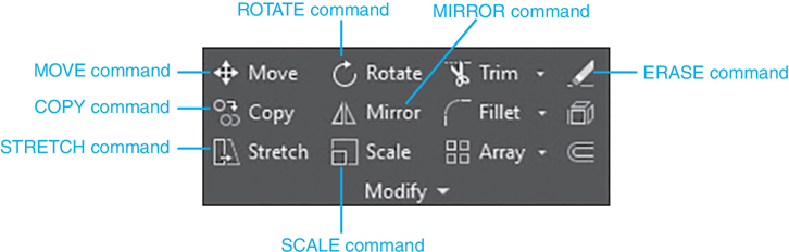
Figure 7-1 The Modify panel
In this chapter, you’ll learn how to modify an object, or a group of objects, using two different approaches:
Activating a modify command and then selecting the object(s) you want to modify (verb/noun)
Selecting the object(s) to modify and then activating a modify command (noun/verb)
The noun/verb terminology might seem a little confusing at first, but if you consider that nouns represent objects (lines, circles, text, etc.) and that verbs represent actions (move, copy, rotate, etc.), it makes sense:
Noun = Drawing object
Verb = AutoCAD command
Note
You can display the Options dialog box using the following techniques:
Select Options from the bottom of the application menu (big A).
Right-click with your mouse at the command line and select Options… from the Command Line shortcut menu.
Right-click with your mouse when nothing is selected in the drawing window, and select Options… from the Default shortcut menu.
Type OP or Options.
The traditional approach to editing in AutoCAD is verb/noun—activate the command first and then select the object(s). The alternate noun/verb approach to editing can actually be disabled—it is on by default. The noun/verb selection mode and other object selection features are controlled on the Selection tab of the Options dialog box shown in Figure 7-2.
Many of the settings located on the Selection tab are explained throughout this chapter. For now, make sure that your Selection modes settings match those shown in Figure 7-2. Failure to do so can cause some of the examples and exercises in this chapter to behave differently than anticipated.
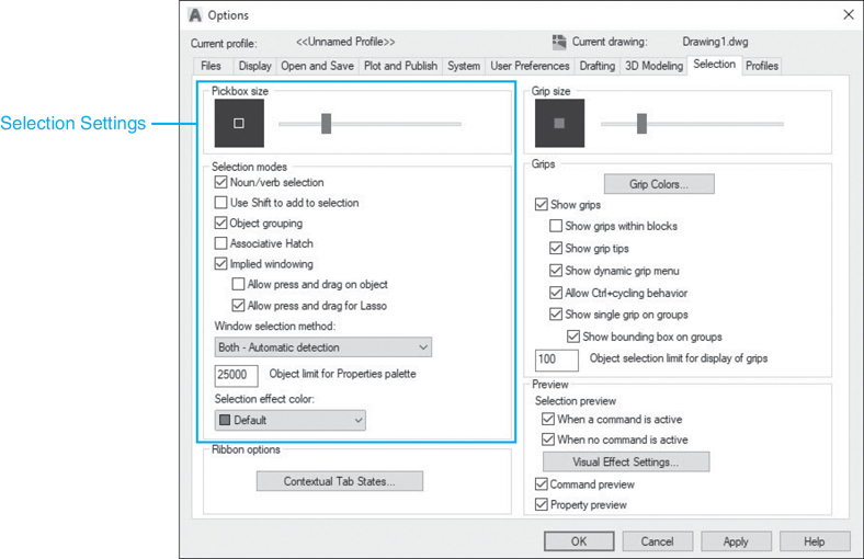
Figure 7-2 Selection settings on the Selection tab of the Options dialog box
The ERASE Command
In order to explain the different ways to select objects using either the verb/noun approach or the noun/verb approach, we first need a verb, or command. The ERASE command is a good candidate, considering that it is probably the most used of all the modify commands. The ERASE command removes, or erases, the selected objects from a drawing.
Erase |
|
|---|---|
Ribbon & Panel: |
Home | Modify |
Menu: |
Modify | Erase |
Command Line: |
ERASE |
Command Alias: |
E |
Tip
If you erase something by accident, remember that you can always use the UNDO command to bring it back. You can either select the Undo tool from the Quick Access toolbar or simply type U<Enter> at the AutoCAD command line. Entering U repeatedly at the command line will undo commands one at a time until you reach the beginning of your drawing session.
Selecting Objects for Editing
As described in the introduction, there are two ways to edit information in AutoCAD—verb/noun and noun/verb. The beginning of this chapter concentrates on the traditional verb/noun approach of activating the command first and then selecting the object(s). Once we understand this approach, we can explore the noun/verb way of doing things. The basics of the modify commands remain the same.
All modify commands work by modifying objects contained in what is referred to as a selection set in AutoCAD.
selection set: One or more selected objects that are treated as one unit by an AutoCAD command.
A selection set is simply the object, or objects, that you select to be modified. Any time you activate an AutoCAD modify command, and no objects are already selected, AutoCAD prompts you to create a selection set as follows:
Select objects:
This is your cue to start selecting the object(s) in your drawing that you want to modify. AutoCAD repeats the Select objects: prompt until you “accept” the selection set by pressing <Enter> without selecting anything. This approach allows you to build a selection set using multiple selection techniques ranging from picking objects individually with your mouse to selecting multiple objects using the different selection set options explained in this chapter.
Selecting Objects Individually
Selecting objects individually is the default selection mode. Any time AutoCAD prompts you to Select objects: to create a selection set, the cursor crosshairs change to what is referred to as the pickbox.
pickbox: Square box that replaces the cursor crosshairs whenever AutoCAD prompts you to Select objects:. It is used to pick objects in a drawing to create a selection set.
The size of the pickbox is used to determine how close you need to be to an object in order to select it. To select an object, it must be within or touching the pickbox. By default, objects that are within the pickbox are previewed by highlighting the objects so that they become thicker and darker or lighter depending on the screen background color (see Figure 7-3). This selection preview feature provides you feedback regarding what object will be selected before you pick with your mouse so that you don’t pick the wrong object unintentionally.
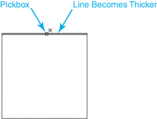
Figure 7-3 The selection preview feature
Tip
You can control the size of the pickbox and turn the selection preview feature on and off via the Selection tab of the Options dialog box shown in Figure 7-2. Other selection preview features are controlled via the Visual Effect Settings dialog box, which can be displayed by selecting the Visual Effect Settings. . . button in the Selection preview area.
Picking an object adds it to the current selection set and highlights it. See Figure 7-4.

Figure 7-4 Highlighted object
You also get feedback at the command line informing you that one object was found:
Select objects: 1 found
Select objects:
AutoCAD stays in the selection mode until you press the <Enter> key without selecting anything to accept the selection set. This allows you to continue to add to the selection set by selecting more objects. As objects are selected, AutoCAD prompts you if the object was found and keeps a running tally of how many total objects are part of the current selection set:
Select objects: 1 found, 2 total
Select objects:
You can enter U<Enter> in response to the Select objects: prompt to undo, or deselect, the last object selected. If you have more than one object selected, you can enter U<Enter> repeatedly to deselect multiple objects in the order they were selected.
Tip
You can also remove selected objects from the selection set by holding down the <Shift> key and selecting the object you want to remove.
If you try to select an object and you miss because the object isn’t within the pickbox, you may automatically be put in what is known as implied windowing mode, depending on whether it is turned on or not.
implied windowing: Feature that allows you to create a window, crossing, or lasso selection automatically by picking an empty space in a drawing to define the first corner point.
Implied windowing is turned on and off on the Selection tab of the Options dialog box shown in Figure 7-2. If Implied windowing mode is on, AutoCAD automatically initiates the Window option. The Window option is discussed in detail a little later in this section. For the time being, you can hit the <Esc> key to exit the window selection mode and return to selecting objects individually.
Toggling Between Adding and Removing Objects from a Selection Set. It is possible to toggle between adding and removing objects from a selection set using the A (Add) and R (Remove) selection set options. If you type R<Enter> in response to the Select objects: prompt, AutoCAD enters the Remove object mode, and the prompt changes to Remove objects:. Objects you then select are removed from the selection set so that they are no longer highlighted. AutoCAD stays in the Remove object mode until you enter A<Enter> in response to the Remove objects: prompt to switch back to Add object mode. Switching to Add object mode changes the prompt back to the familiar Select objects: prompt.
Note
The Add and Remove toggle also works with all the multiple object selection modes described later in this chapter.
Using the <Shift> Key to Add to a Selection Set. When selecting objects individually, it is possible to change the selection mode so that you must use the <Shift> key when adding objects to the current selection set. If you select the Use Shift to add to selection check box in the Selection modes area on the Selection tab of the Options dialog box (see Figure 7-2) so that it is turned on, you must hold down the <Shift> key when selecting more than one object. When the Use Shift to add to selection mode is on and you try to select more than one object without using the <Shift> key, the first object is deselected so it is no longer highlighted. By default, the Use Shift to add to selection mode is off.
Selecting Stacked and Overlaid Objects. It is possible to easily select overlapping objects either by picking the Selection Cycling button on the AutoCAD status bar shown in Figure 7-5 or by using the <Ctrl>+W keyboard combination.

Figure 7-5 The Selection Cycling button on the status bar
Note
By default, the Selection Cycling button is not displayed on the status bar. It can be turned on using the Customization menu on the far right of the status bar.
When selection cycling is turned on and you try to select an object that overlaps one or more other objects, AutoCAD displays a list of all the overlapping objects that you can select from, so you can select the desired object. When you pass your cursor over an object in the list, AutoCAD highlights the object in the drawing so you know which object in the list it is associated with, as shown in Figure 7-6.

Figure 7-6 The Selection Cycling list of overlapping objects
Select the object from the list, and it becomes part of a new or existing selection set.
Note
When you hover your cursor over any overlapping objects in a drawing, a small icon representing two overlapping squares is displayed indicating stacked objects. This is your cue that, if you pick a point, the Selection Cycling list in Figure 7-6 will be displayed so you can select the correct object.
Exercise 7-1 Selecting Objects Individually
![]() Start a new drawing using the acad.dwt drawing template.
Start a new drawing using the acad.dwt drawing template.
![]() Make sure that your Selection modes settings on the Selection tab of the Options dialog box match those shown in Figure 7-2.
Make sure that your Selection modes settings on the Selection tab of the Options dialog box match those shown in Figure 7-2.
![]() Draw a 2×2 square similar to the one shown in Figure 7-3 using the LINE command so that the rectangle consists of four separate line segments. Do not use the RECTANG command!
Draw a 2×2 square similar to the one shown in Figure 7-3 using the LINE command so that the rectangle consists of four separate line segments. Do not use the RECTANG command!
![]() Start the ERASE command.
Start the ERASE command.
![]() Select the top line as shown in Figure 7-4 and press <Enter>. The line is erased.
Select the top line as shown in Figure 7-4 and press <Enter>. The line is erased.
![]() Type U<Enter> or select the Undo tool so that the line is undeleted.
Type U<Enter> or select the Undo tool so that the line is undeleted.
![]() Start the ERASE command again.
Start the ERASE command again.
![]() Select the top line as shown in Figure 7-4.
Select the top line as shown in Figure 7-4.
![]() Select the other three lines in a clockwise direction using your cursor so that all the rectangle lines are highlighted.
Select the other three lines in a clockwise direction using your cursor so that all the rectangle lines are highlighted.
![]() Type U<Enter> three times so that only the top line is highlighted as shown in Figure 7-4.
Type U<Enter> three times so that only the top line is highlighted as shown in Figure 7-4.
![]() Select the other three lines again in a clockwise direction using your cursor so that all the square lines are highlighted.
Select the other three lines again in a clockwise direction using your cursor so that all the square lines are highlighted.
![]() Hold down the <Shift> key, and select the vertical line on the left side of the square so it is no longer highlighted.
Hold down the <Shift> key, and select the vertical line on the left side of the square so it is no longer highlighted.
![]() Type R<Enter>.
Type R<Enter>.
![]() Select the remaining three highlighted lines so that all the square lines are no longer highlighted.
Select the remaining three highlighted lines so that all the square lines are no longer highlighted.
![]() Type A<Enter>.
Type A<Enter>.
![]() Select all four lines so that the entire square is highlighted again, and press <Enter> so that the square is erased.
Select all four lines so that the entire square is highlighted again, and press <Enter> so that the square is erased.
![]() Type U<Enter> or select the Undo tool so that the square is undeleted.
Type U<Enter> or select the Undo tool so that the square is undeleted.
Selecting Multiple Objects
Oftentimes, you need to select more than one object when modifying a drawing. Suppose you need to erase a large portion of your drawing—you don’t want to have to pick each object individually. Doing so would be very time-consuming. Fortunately, AutoCAD provides a number of selection set options that expedite the process of selecting multiple objects. All these options are entered via the keyboard in response to the Select objects: prompt. The following sections explain each of these selection set options.
W—Window Option. The Window option allows you to define a rectangular window selection area by prompting you to pick two corner points as shown in Figure 7-7.
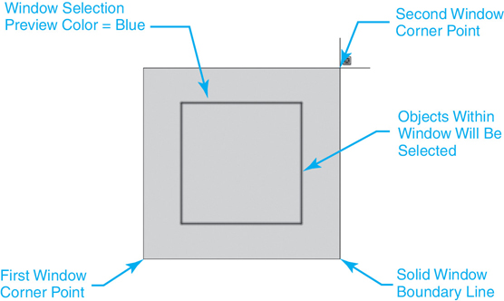
Figure 7-7 Defining the window selection area
By default, the windowed area is shaded a semitransparent blue color to make it obvious which objects will be selected before the second corner point is picked. This selection preview feature helps you avoid the unintentional selection of objects.
Using the Window option, only objects that are completely within the window boundary area are selected. Objects that cross the window boundary are ignored (see Figure 7-8).

Figure 7-8 Objects selected using the Window option
Tip
Recall from Chapter 6 that objects on frozen or locked layers are not affected by any of the selection methods explained in the chapter. You can use this to your advantage when selecting multiple objects so that you can select a large group of objects but filter out the objects you don’t want to be part of the selection set.
Exercise 7-2 Selecting Multiple Objects with the Window Option
![]() Continue from Exercise 7-1.
Continue from Exercise 7-1.
![]() Start the ERASE command.
Start the ERASE command.
![]() Type W<Enter>.
Type W<Enter>.
![]() Create a window selection similar to the one shown in Figure 7-7, and press <Enter> twice. The four lines of the square are erased.
Create a window selection similar to the one shown in Figure 7-7, and press <Enter> twice. The four lines of the square are erased.
![]() Type U<Enter> or select the Undo tool so that the square is undeleted.
Type U<Enter> or select the Undo tool so that the square is undeleted.
C—Crossing Option. The Crossing option allows you to define a rectangular window selection area by picking two corner points similar to the Window option, as shown in Figure 7-9.
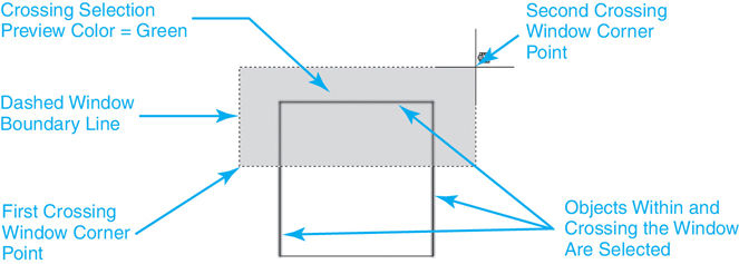
Figure 7-9 Defining the crossing selection area
To distinguish between the Window option and the Crossing option, the Crossing option window boundary is dashed (see Figure 7-9), whereas the Window option window boundary is solid (see Figure 7-7). In addition, the Crossing option windowed area is, by default, shaded a semitransparent green color (see Figure 7-9) instead of the default blue color used with the Window option (see Figure 7-7).
The major difference between the Crossing option and the Window option is that the Crossing option will select objects that cross over the rectangular window boundary in addition to the objects that lie completely within the window boundary area (see Figure 7-10).

Figure 7-10 Objects selected using the Crossing option
Tip
You can control the window selection shading features via the Visual Effect Settings dialog box, which can be displayed by selecting the Visual Effect Settings. . . button in the Selection preview area on the Selection tab of the Options dialog box shown in Figure 7-2.
Exercise 7-3 Selecting Multiple Objects with the Crossing Option
![]() Continue from Exercise 7-2.
Continue from Exercise 7-2.
![]() Start the ERASE command.
Start the ERASE command.
![]() Type C<Enter>.
Type C<Enter>.
![]() Create a crossing selection similar to the one shown in Figure 7-9 and press <Enter> twice. The top horizontal line and the two vertical lines of the square are erased. The bottom horizontal line remains in the drawing.
Create a crossing selection similar to the one shown in Figure 7-9 and press <Enter> twice. The top horizontal line and the two vertical lines of the square are erased. The bottom horizontal line remains in the drawing.
![]() Type U<Enter> or select the Undo tool so that the three lines are undeleted.
Type U<Enter> or select the Undo tool so that the three lines are undeleted.
Implied Windowing. As mentioned earlier in the section “Selecting Objects Individually,” it is possible to initiate the Window, Crossing, or Lasso option automatically by relying on a feature called implied windowing. Implied windowing can be turned on and off on the Selection tab of the Options dialog box shown in Figure 7-2.
When Implied windowing is on, you can initiate the Window, Crossing, or Lasso option by picking an empty space in your drawing so that no objects fall within your pickbox in response to the Select objects or ![]() prompt. If you pick and release the mouse button, AutoCAD interprets the pick point as the first corner point of a rectangular window area and prompts you to select the second corner point as follows:
prompt. If you pick and release the mouse button, AutoCAD interprets the pick point as the first corner point of a rectangular window area and prompts you to select the second corner point as follows:
Specify opposite corner:
This is where it gets interesting. If you move your cursor to the right of the first pick point, you initiate the Window option—the window boundary outline is solid, and the default shade color is blue (see Figure 7-7).
If you move your cursor to the left of the first pick point, you initiate the Crossing option—the window boundary outline is dashed, and the default shade color is green (see Figure 7-9).
In addition to the implied Window and Crossing options, it is also possible to select objects using an implied Lasso option. This option allows you to select the objects you want to by holding the mouse button down after clicking in an empty space in the drawing and dragging a lasso around the objects as shown in Figure 7-11.

Figure 7-11 Selecting objects using the Lasso option
Note
The Lasso option also allows you to apply the Window or Crossing option. Clicking and dragging the cursor to the right creates a Window-type lasso. Clicking and dragging the cursor to the left creates a Crossing-type lasso. You can press the spacebar when creating a lasso selection to switch between the two options.
Tip
The Lasso drag mode is enabled by selecting the Allow press and drag for Lasso check box in the Selection modes area on the Selection tab of the Options dialog box (see Figure 7-2). By default, the Allow press and drag for Lasso selection mode is turned on.
Exercise 7-4 Selecting Multiple Objects with an Implied Window
![]() Continue from Exercise 7-3.
Continue from Exercise 7-3.
![]() Start the ERASE command.
Start the ERASE command.
![]() Pick a point to the lower left of the square so that no objects are within your pickbox, and pick a point.
Pick a point to the lower left of the square so that no objects are within your pickbox, and pick a point.
![]() Release the mouse button, and move the cursor up to the right of the square so that an implied window similar to the window selection shown in Figure 7-7 is created, and pick a point.
Release the mouse button, and move the cursor up to the right of the square so that an implied window similar to the window selection shown in Figure 7-7 is created, and pick a point.
![]() Press <Enter>. The four lines of the square are erased.
Press <Enter>. The four lines of the square are erased.
![]() Type U<Enter> or select the Undo tool so that the four lines are undeleted.
Type U<Enter> or select the Undo tool so that the four lines are undeleted.
![]() Start the ERASE command again.
Start the ERASE command again.
![]() Pick a point to the upper right of the square so that no objects are within your pickbox, and pick a point.
Pick a point to the upper right of the square so that no objects are within your pickbox, and pick a point.
![]() Release the mouse button and move the cursor down and to the left of the square so that an implied window similar to the crossing selection shown in Figure 7-9 is created, and pick a point.
Release the mouse button and move the cursor down and to the left of the square so that an implied window similar to the crossing selection shown in Figure 7-9 is created, and pick a point.
![]() Press <Enter>. The top horizontal line and the two vertical lines of the square are erased. The bottom horizontal line remains in the drawing.
Press <Enter>. The top horizontal line and the two vertical lines of the square are erased. The bottom horizontal line remains in the drawing.
![]() Type U<Enter> or select the Undo tool so that the three lines are undeleted.
Type U<Enter> or select the Undo tool so that the three lines are undeleted.
![]() Start the ERASE command again.
Start the ERASE command again.
![]() Pick a point to the lower left of the square so that no objects are within your pickbox.
Pick a point to the lower left of the square so that no objects are within your pickbox.
![]() Drag the mouse up and to the right to create a lasso similar to the lasso selection shown in Figure 7-11.
Drag the mouse up and to the right to create a lasso similar to the lasso selection shown in Figure 7-11.
![]() Press <Enter>. The four lines of the square are erased.
Press <Enter>. The four lines of the square are erased.
![]() Type U<Enter> or select the Undo tool so that the four lines are undeleted.
Type U<Enter> or select the Undo tool so that the four lines are undeleted.
Tip
It is also possible to use the Window Polygon, Crossing Polygon, and Fence selection options discussed in the next sections when using the implied windowing technique. All three of these options are available after picking the first implied window point via the command line or dynamic input.
WP—Window Polygon Option. The Window Polygon option allows you to define a polygonal window area using multiple pick points so that you can select multiple objects in a complex drawing that you might not be able to select using a simple rectangular window. When you enter the WP option, AutoCAD prompts you for the first polygon point and then prompts you for line endpoints until you press <Enter> as shown in Figure 7-12.

Figure 7-12 Defining the window polygon selection area
Similar to the Window option, the Window Polygon option selects only objects that are completely within the window boundary area. Objects that cross the window boundary are ignored (see Figure 7-13).
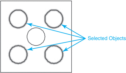
Figure 7-13 Objects selected using the Window Polygon option
Tip
All the multiple selection options that rely on more than two pick points have an Undo option that allows you to “unpick” points you have already selected so that you can relocate an errant pick point without canceling and starting over. To use the Undo option, type U<Enter> in response to a prompt for the next point, and the last point will be erased.
Exercise 7-5 Selecting Multiple Objects with a Window Polygon
![]() Continue from Exercise 7-4.
Continue from Exercise 7-4.
![]() Add five circles so your drawing looks like Figure 7-12.
Add five circles so your drawing looks like Figure 7-12.
![]() Start the ERASE command.
Start the ERASE command.
![]() Type WP<Enter>.
Type WP<Enter>.
![]() Create a window polygon selection similar to the one shown in Figure 7-12, and press <Enter> twice. The four circles at the corners of the square are erased.
Create a window polygon selection similar to the one shown in Figure 7-12, and press <Enter> twice. The four circles at the corners of the square are erased.
![]() Type U<Enter> or select the Undo tool so that the four circles are undeleted.
Type U<Enter> or select the Undo tool so that the four circles are undeleted.
CP—Crossing Polygon Option. The Crossing Polygon option works similarly to the Window Polygon option. It also allows you to define a polygonal window area using multiple pick points except that, like the Crossing option, objects that cross the polygon window are also selected. When you enter the CP option, AutoCAD prompts you for the first polygon point and then prompts you for line endpoints until you press <Enter>, as shown in Figure 7-14.
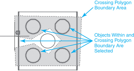
Figure 7-14 Defining the crossing polygon selection area
As noted, the Crossing Polygon option selects objects that cross over the polygon window boundary in addition to the objects that lie completely within the window boundary area (see Figure 7-15).

Figure 7-15 Objects selected using the Crossing Polygon option
Exercise 7-6 Selecting Multiple Objects with a Crossing Polygon
![]() Continue from Exercise 7-5.
Continue from Exercise 7-5.
![]() Start the ERASE command.
Start the ERASE command.
![]() Type CP<Enter>.
Type CP<Enter>.
![]() Create a Crossing Polygon selection similar to the one shown in Figure 7-14, and press <Enter> twice. The four circles at the corners and the two vertical lines of the square are erased.
Create a Crossing Polygon selection similar to the one shown in Figure 7-14, and press <Enter> twice. The four circles at the corners and the two vertical lines of the square are erased.
![]() Type U<Enter> or select the Undo tool so that the four circles and two lines are undeleted.
Type U<Enter> or select the Undo tool so that the four circles and two lines are undeleted.
Note
Both the Window Polygon and Crossing Polygon options interact the same as their Window and Crossing counterparts so that a solid window boundary is used for the Window Polygon option and a dashed window boundary is used for the Crossing Polygon option. The window selection shading feature settings are also shared between the corresponding options.
F—Fence Option. The Fence option allows you to define a multisegmented fence line that selects everything it crosses, similar to the Crossing option. When you enter the F option, AutoCAD prompts you for the first fence point and then prompts you for additional fence endpoints until you press <Enter> as shown in Figure 7-16.
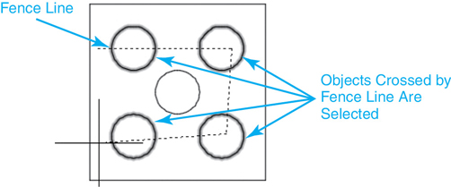
Figure 7-16 Defining the fence selection line
The Fence option selects all objects that the fence line crosses over or touches (see Figure 7-17).
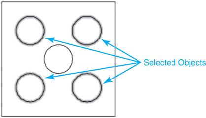
Figure 7-17 Objects selected using the Fence option
Exercise 7-7 Selecting Multiple Objects with a Fence
![]() Continue from Exercise 7-6.
Continue from Exercise 7-6.
![]() Start the ERASE command.
Start the ERASE command.
![]() Type F<Enter>.
Type F<Enter>.
![]() Create a Fence selection similar to the one shown in Figure 7-16, and press <Enter> twice. The four circles at the corners of the square are erased.
Create a Fence selection similar to the one shown in Figure 7-16, and press <Enter> twice. The four circles at the corners of the square are erased.
![]() Type U<Enter> or select the Undo tool so that the four circles are undeleted.
Type U<Enter> or select the Undo tool so that the four circles are undeleted.
Advanced Selection Techniques
The following selection set options provide additional ways to select objects without having to pick any points in your drawing.
All—All Option. The All option selects all the objects in a drawing—even those objects that lie outside the visible drawing window! Because of this, care should be taken when using it. When used properly, it can be a handy way to modify everything in a drawing.
Tip
Objects that are on frozen or locked layers are protected when using the All option so that they are not selected.
L—Last Option. The Last option selects the last object created in a drawing. For instance, if you draw a line in a drawing and then enter the ERASE command, entering L in response to the Select objects: prompt highlights and selects the line you just drew.
P—Previous Option. The Previous option recalls the last selection set created so that you can modify the same objects again. If no previous selection set exists, AutoCAD displays the following at the command line:
No previous selection set.
Selecting Similar Objects
The Select Similar tool allows you to select an object and then automatically include all of the other objects in the drawing that are of the same type and share the same properties. The easiest way to use the Select Similar tool is to select one or more objects and right-click to display the Edit shortcut menu shown in Figure 7-18, which includes the tool.

Figure 7-18 Right-click menu with Select Similar tool
You can control which properties are matched when creating the selection set by entering SELECTSIMILAR at the command line. The SELECTSIMILAR command has a Setting option that displays the Select Similar Settings dialog box shown in Figure 7-19 so you can select the properties to filter by.

Figure 7-19 The Select Similar Settings dialog box
Exercise 7-8 Using Advanced Selection Techniques
![]() Continue from Exercise 7-7.
Continue from Exercise 7-7.
![]() Start the ERASE command.
Start the ERASE command.
![]() Type All<Enter>.
Type All<Enter>.
![]() Press <Enter> again. All the drawing objects are erased.
Press <Enter> again. All the drawing objects are erased.
![]() Type U<Enter> or select the Undo tool so that everything is undeleted.
Type U<Enter> or select the Undo tool so that everything is undeleted.
![]() Start the ERASE command again.
Start the ERASE command again.
![]() Type L<Enter>.
Type L<Enter>.
![]() Press <Enter> again. The last object added to the drawing is erased.
Press <Enter> again. The last object added to the drawing is erased.
![]() Type U<Enter> or select the Undo tool so that the object is undeleted.
Type U<Enter> or select the Undo tool so that the object is undeleted.
Grouping Objects
It is possible to group multiple objects together so they act as one unit using the grouping tools found on the Groups panel on the Home tab of the ribbon shown in Figure 7-20.
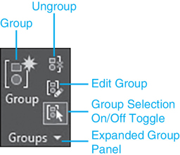
Figure 7-20 The Groups panel
Groups can be either unnamed or named and are stored in the drawing between drawing sessions until they are either exploded or erased. The different grouping tools found on the Groups panel allow you to do the following:
Group Creates an unnamed (default) or named group by selecting objects
Ungroup Explodes or ungroups an existing group
Edit Group Adds or removes individual objects from a group and also allows you to rename a group
Group Selection On/Off Turns group selection on and off so it is possible to select individual group objects if necessary
Additional group management features are provided by selecting the Group Manager tool on the expanded Groups panel accessible by clicking on the down arrow in the right of the panel title bar shown in Figure 7-20. Selecting the Group Manager tool displays the Object Grouping dialog box shown in Figure 7-21.
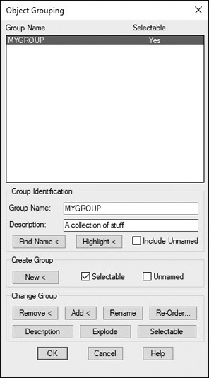
Figure 7-21 The Object Grouping dialog box
The different features and options in the Object Grouping dialog box include:
Group Identification
Group Name Name of group, if there is any. Group names can be up to 31 characters long and can include letters and numbers but no spaces. It is possible to use a hyphen (-) or underscore (_). The name is always converted to uppercase
Description Description of the selected group, if there is any. Descriptions may be up to 64 characters long
Find Name Allows you to select an object and list the group(s) it belongs to in the Group Member List dialog box
Highlight Highlights the members of the selected group in the drawing window
Include Unnamed Determines whether unnamed groups are listed. When this check box is unselected, only named groups are displayed
Create Group
New Creates a new group using the selected objects with the name and description specified
Selectable Determines whether a new group is selectable in the drawing
Unnamed Specifies that a new group has no name. A default name is assigned (*An) where “n” represents a number that increases each time a new group is created
Change Group
Remove Allows you to remove objects from the selected group. You must first uncheck the Selectable option before you can remove any objects.
Add Allows you to add objects to the selected group
Rename Renames the selected group to the name specified in the Group Name: text box
Re-Order Allows you to change the numerical order of objects within the selected group using the Order Group dialog box. By default, objects are numbered in the order in which you select them for inclusion in the group
Description Updates the selected group’s description using the name entered in the Description: text box at the top
Explode Explodes selected group back to individual objects and removes group definition from the drawing
Selectable Toggles selected group’s Selectable property on and off
Tip
The Group Bounding Box toggle, which is also located on the expanded Groups panel, allows you to control the box that is displayed around all of the objects in the group.
Moving Objects
Now that you are familiar with all the different ways to select objects, it’s time for some action. The MOVE command moves objects a user-supplied distance and angle.
Move |
|
|---|---|
Ribbon & Panel: |
Home | Modify |
Menu: |
Modify | Move |
Command Line: |
MOVE |
Command Alias: |
M |
When you start the MOVE command, AutoCAD prompts you to Select objects:. Select the object(s) you want to move, and press <Enter> to accept the selection set. AutoCAD then prompts you to Specify base point or ![]() . You have three options:
. You have three options:
![]() Specify a base point.
Specify a base point.
![]() Select the Displacement option.
Select the Displacement option.
![]() Enter a displacement distance using Cartesian coordinates.
Enter a displacement distance using Cartesian coordinates.
Using the first option, you typically pick a base (from) point by snapping to a key object feature using an object snap. You can then pick a destination (to) point, and the selected objects are moved to the new location (see Figure 7-22).

Figure 7-22 Moving objects using mouse pick points
Note
It is also possible to type a base point as a Cartesian coordinate value at the cursor or the command line. You can then specify a destination point either by using your mouse or by entering an absolute, relative, or polar coordinate value.
You can also use direct distance entry to locate the second point. Using direct distance, you simply point the direction you want to move the selected object(s) and type in the distance you want to travel (see Figure 7-23).
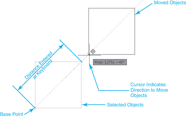
Figure 7-23 Moving objects using direct distance
Tip
Remember that the best way to utilize direct distance entry is to use it in conjunction with either Polar Tracking or Ortho Mode. Using either of these drawing tools allows you to lock in an angle and enter a distance for precise movement.
The Displacement option allows you to specify a displacement distance using rectangular or polar coordinates. The coordinate value you enter is always the relative distance the selected object(s) will be moved, even if you omit the @ sign.
You can enter the displacement distance using either rectangular (x,y) or polar (@distance<angle) coordinates. Entering 3,3<Enter> results in the move operation shown in Figure 7-24.
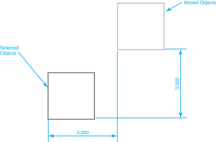
Figure 7-24 Moving objects using the Displacement option
Tip
AutoCAD remembers the displacement distance entered so that it is now the default distance. The next time you use the MOVE command, you can just press <Enter> to move the same distance again.
The third option is basically a shortcut to the Displacement option explained previously. It is possible to enter a Cartesian coordinate displacement distance directly in response to the first Specify base point or ![]() prompt explained earlier. Entering an x,y distance and pressing <Enter> displays the standard prompt Specify second point or <use first point as displacement>:. Pressing <Enter> selects the default <use first point as displacement> option so that the x,y distance entered is used as the displacement distance.
prompt explained earlier. Entering an x,y distance and pressing <Enter> displays the standard prompt Specify second point or <use first point as displacement>:. Pressing <Enter> selects the default <use first point as displacement> option so that the x,y distance entered is used as the displacement distance.
Exercise 7-9 Moving Objects
![]() Continue from Exercise 7-8.
Continue from Exercise 7-8.
![]() Start the MOVE command, and select the square using your preferred selection method so that AutoCAD prompts Specify base point or
Start the MOVE command, and select the square using your preferred selection method so that AutoCAD prompts Specify base point or ![]() .
.
![]() Snap to the lower-left corner of the square using the Endpoint object snap as shown in Figure 7-22.
Snap to the lower-left corner of the square using the Endpoint object snap as shown in Figure 7-22.
![]() Move the square using a second pick point as shown in Figure 7-22.
Move the square using a second pick point as shown in Figure 7-22.
![]() Type U<Enter> or select the Undo tool so that the square is in its original location.
Type U<Enter> or select the Undo tool so that the square is in its original location.
![]() Start the MOVE command again, and select the square using your preferred selection method so that AutoCAD prompts Specify base point or
Start the MOVE command again, and select the square using your preferred selection method so that AutoCAD prompts Specify base point or ![]() .
.
![]() Snap to the lower-left corner of the square using the Endpoint object snap as shown in Figure 7-23.
Snap to the lower-left corner of the square using the Endpoint object snap as shown in Figure 7-23.
![]() Move your cursor so the rubber-band line points to the right as shown in Figure 7-23, and type 3<Enter>. The square moves 3 units along the rubber-band line.
Move your cursor so the rubber-band line points to the right as shown in Figure 7-23, and type 3<Enter>. The square moves 3 units along the rubber-band line.
NOTE
It is possible, and quite common, to use object snaps when modifying objects, especially when selecting a base point
![]() Type U<Enter> or select the Undo tool so that the square is in its original location.
Type U<Enter> or select the Undo tool so that the square is in its original location.
![]() Start the MOVE command again, and select the square using your preferred selection method so that AutoCAD prompts Specify base point or
Start the MOVE command again, and select the square using your preferred selection method so that AutoCAD prompts Specify base point or ![]() .
.
![]() Type 3,3<Enter>. AutoCAD prompts Specify second point or <use first point as displacement>:.
Type 3,3<Enter>. AutoCAD prompts Specify second point or <use first point as displacement>:.
![]() Press <Enter> again to use the first point entered as the displacement distance. The square moves +3 units on the X-axis and +3 units on the Y-axis, as shown in Figure 7-24.
Press <Enter> again to use the first point entered as the displacement distance. The square moves +3 units on the X-axis and +3 units on the Y-axis, as shown in Figure 7-24.
![]() Type U<Enter> or select the Undo tool so that the square is in its original location.
Type U<Enter> or select the Undo tool so that the square is in its original location.
Copying Objects
The COPY command copies objects a user-supplied distance and angle. Its usage is similar to the MOVE command except that the COPY command maintains the selected objects in their original location. It is possible to make multiple copies if you specify a base point.
COPY |
|
|---|---|
Ribbon & Panel: |
Home | Modify |
Command Line: |
COPY |
Command Alias: |
CO |
After you start the COPY command and select something, AutoCAD prompts you to Specify base point or ![]() . Similar to the MOVE command, you initially have these options:
. Similar to the MOVE command, you initially have these options:
![]() Specify a base point.
Specify a base point.
![]() Select the Displacement option.
Select the Displacement option.
![]() Enter a displacement distance using Cartesian coordinates.
Enter a displacement distance using Cartesian coordinates.
Note
The mode option allows you to switch between making multiple copies (default) and a single copy.
Using the first option, you typically pick a base (from) point by snapping to a key object feature using an object snap. You can then pick a destination (to) point, and the selected objects are copied to the new location as shown in Figure 7-25.

Figure 7-25 Copying objects using mouse pick points
Just like the MOVE command, you can also rely on direct distance entry to locate the second point. Using direct distance, you simply point the direction you want to copy the selected object(s) and type in the distance you want to travel.
Tip
The COPY command has an Undo option when you are making multiple copies so that you can undo a copy operation if it is the wrong location. To use the Undo option, you can either select the option using your arrow keys or type U<Enter>.
If you use the first option and specify a base point, AutoCAD remains in the COPY command after the first copy is created so that it is possible to make multiple copies by specifying multiple destination points. After making the first copy, AutoCAD repeatedly prompts you to Specify second point or ![]() until you end the command, as shown in Figure 7-26.
until you end the command, as shown in Figure 7-26.

Figure 7-26 Copying multiple objects
The Displacement option allows you to specify a displacement distance using rectangular or polar coordinates. The coordinate value you enter is always the relative distance the selected object(s) will be copied, even if you omit the @ sign.
After you select the Displacement option, you can enter the displacement distance using either rectangular (x,y) or polar (@distance<angle) coordinates. Entering 3,3<Enter> results in the copy operation shown in Figure 7-27.

Figure 7-27 Copying objects using the Displacement option
Tip
AutoCAD remembers the displacement distance entered so that it is now the default distance. The next time you use the COPY command, you can just press <Enter> to copy the same distance again.
Similar to the MOVE command, it is possible to enter a Cartesian coordinate displacement distance directly in response to the first Specify base point or ![]() prompt explained earlier. Entering an x,y distance and pressing <Enter> twice selects the default <use first point as displacement> option so that the x,y distance entered is used as the displacement distance.
prompt explained earlier. Entering an x,y distance and pressing <Enter> twice selects the default <use first point as displacement> option so that the x,y distance entered is used as the displacement distance.
The Array option allows you to create a one-dimensional array of objects by specifying the total number of copies and either the distance between each copy or a total distance to automatically fit all of the copies.
Exercise 7-10 Copying Objects
![]() Continue from Exercise 7-9.
Continue from Exercise 7-9.
![]() Start the COPY command, and select the square using your preferred selection method so that AutoCAD prompts Specify base point or
Start the COPY command, and select the square using your preferred selection method so that AutoCAD prompts Specify base point or ![]() .
.
![]() Snap to the lower-left corner of the square using the Endpoint object snap, as shown in Figure 7-25. AutoCAD prompts Specify second point or <use first point as displacement>:.
Snap to the lower-left corner of the square using the Endpoint object snap, as shown in Figure 7-25. AutoCAD prompts Specify second point or <use first point as displacement>:.
![]() Copy the square using a second pick point, as shown in Figure 7-25. AutoCAD repeatedly prompts Specify second point or
Copy the square using a second pick point, as shown in Figure 7-25. AutoCAD repeatedly prompts Specify second point or ![]() .
.
![]() Continue to pick points to make multiple copies, as shown in Figure 7-26.
Continue to pick points to make multiple copies, as shown in Figure 7-26.
![]() Press <Enter>, select the Exit option, or type E<Enter> to end the COPY command.
Press <Enter>, select the Exit option, or type E<Enter> to end the COPY command.
![]() Type U<Enter> or select the Undo tool so that only one square is left in its original location.
Type U<Enter> or select the Undo tool so that only one square is left in its original location.
![]() Start the COPY command, and select the square using your preferred selection method so that AutoCAD prompts Specify second point or
Start the COPY command, and select the square using your preferred selection method so that AutoCAD prompts Specify second point or ![]() .
.
![]() Type 3,3<Enter>. AutoCAD prompts Specify second point or <use first point as displacement>:.
Type 3,3<Enter>. AutoCAD prompts Specify second point or <use first point as displacement>:.
![]() Press <Enter> again to use the first point entered as the displacement distance. The square is copied +3 units on the X-axis and +3 units on the Y-axis, as shown in Figure 7-27.
Press <Enter> again to use the first point entered as the displacement distance. The square is copied +3 units on the X-axis and +3 units on the Y-axis, as shown in Figure 7-27.
![]() Type U<Enter> or select the Undo tool so that only one square is left in its original location.
Type U<Enter> or select the Undo tool so that only one square is left in its original location.
Mirroring Objects
The MIRROR command creates a mirror image of objects about a mirror axis line defined by two user-supplied line endpoints.
Mirror |
|
|---|---|
Ribbon & Panel: |
Home | Modify |
Menu: |
Modify | Mirror |
Command Line: |
MIRROR |
Command Alias: |
MI |
After you start the MIRROR command and select something, AutoCAD prompts you to specify the two endpoints of a line about which to mirror the selected objects as shown in Figure 7-28, while maintaining a ghost image of the original objects and displaying a preview of the mirrored objects.
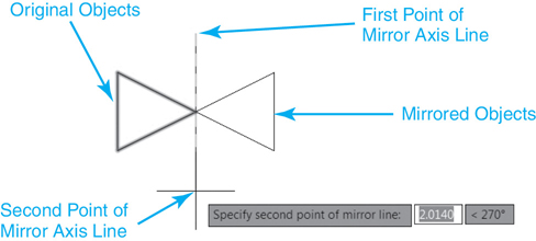
Figure 7-28 Mirroring objects
Tip
You can use either the Ortho Mode or the Polar Tracking tool to create either a horizontal or vertical mirror axis line quickly by simply picking two points.
After selecting the second point, AutoCAD prompts you to Erase source objects? ![]() . You have the option of either erasing the originally selected objects, so only the mirrored copies remain, or leaving them in the drawing. The default is not to erase the original objects so that you can just press <Enter> and end up with the mirrored object and the original, as shown in Figure 7-29.
. You have the option of either erasing the originally selected objects, so only the mirrored copies remain, or leaving them in the drawing. The default is not to erase the original objects so that you can just press <Enter> and end up with the mirrored object and the original, as shown in Figure 7-29.

Figure 7-29 Mirrored objects with original objects maintained
To erase the original objects, select the Yes option in response to the Erase source objects? ![]() prompt. The result of erasing the original objects is shown in Figure 7-30.
prompt. The result of erasing the original objects is shown in Figure 7-30.
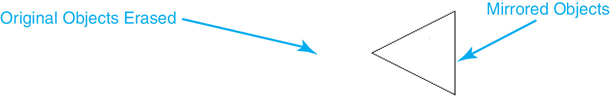
Figure 7-30 Mirrored objects with original objects erased
Mirroring Text
Usually, when you mirror text you want it to retain its original left-to-right orientation so that the text isn’t reversed, as shown in Figure 7-31.
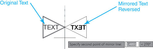
Figure 7-31 Mirrored text—Reversed
The AutoCAD MIRRTEXT system variable controls whether or not text is reversed when it is mirrored. Setting MIRRTEXT to 1 (on) will cause text to be reversed when it is mirrored, as shown in Figure 7-31. Setting MIRRTEXT to 0 (off) retains the text’s original orientation, as shown in Figure 7-32.

Figure 7-32 Mirrored text—Normal
By default, the MIRRTEXT system variable is set to 0 (off).
Exercise 7-11 Mirroring Objects
![]() Continue from Exercise 7-10.
Continue from Exercise 7-10.
![]() Erase the lines that make up the square in your drawing.
Erase the lines that make up the square in your drawing.
![]() Draw a triangle similar to the one shown in Figure 7-28.
Draw a triangle similar to the one shown in Figure 7-28.
![]() Start the MIRROR command, and select the triangle using your preferred selection method so that AutoCAD prompts Specify first point of mirror line:.
Start the MIRROR command, and select the triangle using your preferred selection method so that AutoCAD prompts Specify first point of mirror line:.
![]() Pick a point above the right side vertex as shown in Figure 7-28. AutoCAD prompts you to Specify second point of mirror line:.
Pick a point above the right side vertex as shown in Figure 7-28. AutoCAD prompts you to Specify second point of mirror line:.
![]() Turn on the Ortho Mode drawing tool if it is not already on.
Turn on the Ortho Mode drawing tool if it is not already on.
![]() Pick a point directly below the first point at 270° using the Ortho Mode drawing tool as shown in Figure 7-28. AutoCAD mirrors the triangle and prompts Erase source objects?
Pick a point directly below the first point at 270° using the Ortho Mode drawing tool as shown in Figure 7-28. AutoCAD mirrors the triangle and prompts Erase source objects? ![]() .
.
![]() Press <Enter> to accept the default and retain the original triangle so that the drawing looks similar to Figure 7-29.
Press <Enter> to accept the default and retain the original triangle so that the drawing looks similar to Figure 7-29.
Rotating Objects
The ROTATE command rotates objects a user-specified rotation angle around a user-specified base point.
Rotate |
|
|---|---|
Ribbon & Panel: |
Home | Modify |
Menu: |
Modify | Rotate |
Command Line: |
ROTATE |
Command Alias: |
RO |
After you start the ROTATE command and select something, AutoCAD prompts you to Specify base point:. The base point is the axis of rotation about which the selected object(s) are rotated. Typically you pick a base point by snapping to a key object feature using an object snap.
Note
It is also possible to type in a base point as a Cartesian coordinate value at the cursor or the command line. For instance, to rotate an object using the drawing origin as the base point, you can enter 0,0<Enter> in response to the Specify base point: prompt.
After specifying the base point, AutoCAD then prompts you to Specify rotation angle or ![]() . You have three different ways you can enter the rotation angle:
. You have three different ways you can enter the rotation angle:
![]() Pick a point with your mouse that defines the rotation angle using the base point as the vertex.
Pick a point with your mouse that defines the rotation angle using the base point as the vertex.
![]() Enter the angle at the keyboard.
Enter the angle at the keyboard.
![]() Use the Reference option to reference a start angle, and then enter a new angle either at the keyboard or by picking points.
Use the Reference option to reference a start angle, and then enter a new angle either at the keyboard or by picking points.
Using the first option, you simply move your cursor and pick a point in your drawing to indicate the desired rotation angle. AutoCAD provides a preview of the rotation, as shown in Figure 7-33.
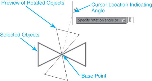
Figure 7-33 Rotating objects using your mouse
Tip
You can use either the Ortho Mode or Polar Tracking tool to quickly rotate object(s) at predefined angles.
The second option is to enter the rotation angle at the keyboard. Angles are measured using the current base angle and direction. The default base angle is 0° = East with angles measured counterclockwise. The current direction and base angle are displayed at the command line when you use the ROTATE command for an easy reference as follows:
Current positive angle in UCS: ANGDIR=clockwise ANGBASE5=θ
Entering 45<Enter> with the settings above rotates the selected objects, as shown in Figures 7-34A and B.
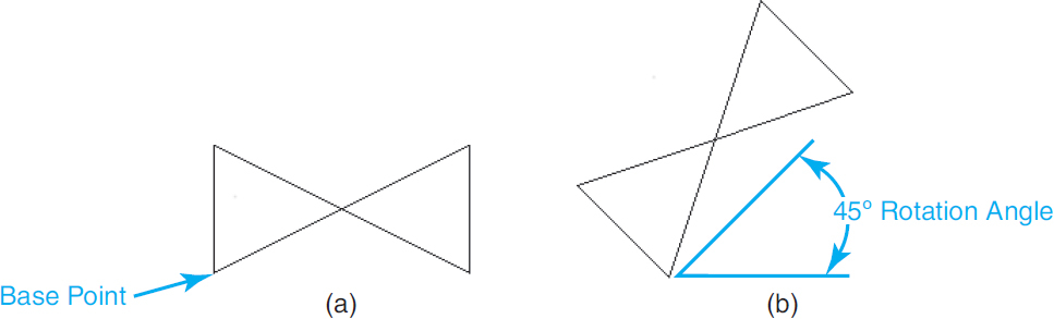
Figure 7-34 A Objects before rotating B Objects rotated 45°
Tip
It is also possible to enter a negative angle and rotate objects in the opposite direction of the current angle direction setting. For example, entering –45° is equal to entering 315°.
The Reference option allows you to rotate object(s) by specifying a reference, or start angle, and then specifying a new, absolute angle to rotate to. AutoCAD determines the necessary rotation angle by calculating the difference from the reference angle to the new angle.
After you select the Reference option, you can either type in an angle via the keyboard, or you can select two points in your drawing that define the reference angle. The Reference option is invaluable if you don’t know the angle of an existing object. Using object snaps, you can snap to two points on the object(s) that define its current angle, as shown in Figure 7-35.
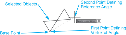
Figure 7-35 Rotating objects using the Reference option—Start angle
AutoCAD then prompts you to Specify the new angle or ![]() . You can either type in an angle via the keyboard, or you can use the Points option to select two points in the drawing to define the new angle, as shown in Figure 7-36.
. You can either type in an angle via the keyboard, or you can use the Points option to select two points in the drawing to define the new angle, as shown in Figure 7-36.
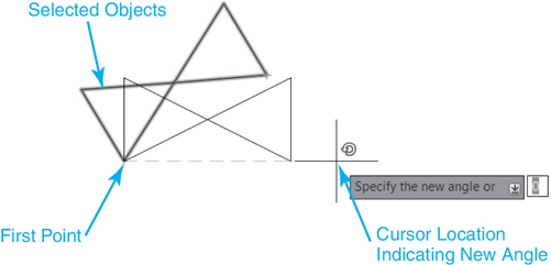
Figure 7-36 Rotating objects using the Reference option—New angle
Rotating and Copying Objects
It is possible to rotate and copy objects using the Copy option. When you select the Copy option, AutoCAD displays the following at the command line:
Rotating a copy of the selected objects.
You can use any of the methods explained earlier to specify a rotation angle. Figure 7-37 shows the results of using the Copy option and rotating the objects shown in Figure 7-34A 90° from horizontal.

Figure 7-37 Rotating and copying objects
Tip
AutoCAD remembers the angle entered using any of the ROTATE command options so that it is now the default angle. The next time you use the ROTATE command, you can press <Enter> to rotate the same angle again.
Exercise 7-12 Rotating Objects
![]() Continue from Exercise 7-11.
Continue from Exercise 7-11.
![]() Start the ROTATE command, and select both triangles using your preferred selection method so that AutoCAD prompts Specify base point or
Start the ROTATE command, and select both triangles using your preferred selection method so that AutoCAD prompts Specify base point or ![]() .
.
![]() Snap to the intersection of both triangles using the Intersection object snap, as shown in Figure 7-33. AutoCAD prompts Specify rotation angle or
Snap to the intersection of both triangles using the Intersection object snap, as shown in Figure 7-33. AutoCAD prompts Specify rotation angle or ![]() .
.
![]() Rotate the triangles to any angle using a cursor pick point, as shown in Figure 7-33.
Rotate the triangles to any angle using a cursor pick point, as shown in Figure 7-33.
![]() Type U<Enter> or select the Undo tool so that the triangles are oriented horizontally again, as shown in Figure 7-34A.
Type U<Enter> or select the Undo tool so that the triangles are oriented horizontally again, as shown in Figure 7-34A.
![]() Start the ROTATE command again, and select the triangles using your preferred selection method so that AutoCAD prompts Specify base point or
Start the ROTATE command again, and select the triangles using your preferred selection method so that AutoCAD prompts Specify base point or ![]() .
.
![]() Snap to the intersection of both triangles using the Intersection object snap, as shown in Figure 7-33. AutoCAD prompts Specify rotation angle or
Snap to the intersection of both triangles using the Intersection object snap, as shown in Figure 7-33. AutoCAD prompts Specify rotation angle or ![]() .
.
![]() Type 45<Enter>. The triangles are rotated 45° as shown in Figure 7-34B.
Type 45<Enter>. The triangles are rotated 45° as shown in Figure 7-34B.
![]() Type U<Enter> or select the Undo tool so that the triangles are oriented horizontally again as shown in Figure 7-34A.
Type U<Enter> or select the Undo tool so that the triangles are oriented horizontally again as shown in Figure 7-34A.
![]() Start the ROTATE command again, and select the triangles using your preferred selection method so that AutoCAD prompts Specify base point or
Start the ROTATE command again, and select the triangles using your preferred selection method so that AutoCAD prompts Specify base point or ![]() .
.
![]() Snap to the intersection of both triangles using the Intersection object snap, as shown in Figure 7-33. AutoCAD prompts Specify rotation angle or
Snap to the intersection of both triangles using the Intersection object snap, as shown in Figure 7-33. AutoCAD prompts Specify rotation angle or ![]() .
.
![]() Select the Copy option.
Select the Copy option.
![]() Type 90<Enter>. The triangles are copied and rotated 90° as shown in Figure 7-37.
Type 90<Enter>. The triangles are copied and rotated 90° as shown in Figure 7-37.
![]() Type U<Enter> or select the Undo tool so that only two triangles are left at their original horizontal orientation.
Type U<Enter> or select the Undo tool so that only two triangles are left at their original horizontal orientation.
Scaling Objects
The SCALE command scales objects a user-specified scale factor about a user-specified base point.
Scale |
|
|---|---|
Ribbon & Panel: |
Home | Modify |
Menu: |
Modify | Scale |
Command Line: |
SCALE |
Command Alias: |
SC |
After starting the SCALE command, AutoCAD prompts you to Specify base point:. The base point is the point about which the selected object(s) are scaled. Typically you pick a base point by snapping to a key object feature using an object snap.
Note
It is also possible to type in a base point as a Cartesian coordinate value at the cursor or the command line. For instance, to scale an object using the drawing origin as the base point, you can enter 0,0<Enter> in response to the Specify base point: prompt.
After specifying the base point, AutoCAD then prompts you to Specify scale factor or ![]() . You have three different ways you can enter the scale factor:
. You have three different ways you can enter the scale factor:
![]() Pick a point with your mouse that defines the scale factor.
Pick a point with your mouse that defines the scale factor.
![]() Enter the scale factor at the keyboard.
Enter the scale factor at the keyboard.
![]() Use the Reference option to reference a starting size/length and then enter a new size/length either at the keyboard or by picking points.
Use the Reference option to reference a starting size/length and then enter a new size/length either at the keyboard or by picking points.
Using the first option you simply move your cursor and pick a point in your drawing to indicate the desired scale factor. AutoCAD provides a preview of the scaling process, as shown in Figure 7-38.
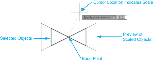
Figure 7-38 Scaling objects using your mouse
The second option is to enter the scale factor at the keyboard. A scale factor greater than 1 makes objects larger, and a scale factor less than 1 makes objects smaller. Scale factors must always be greater than zero. Entering 2<Enter> in response to the Specify scale factor or ![]() prompt scales the selected objects up by a factor of 2 so that they are twice as large, as shown in Figures 7-39A and B.
prompt scales the selected objects up by a factor of 2 so that they are twice as large, as shown in Figures 7-39A and B.
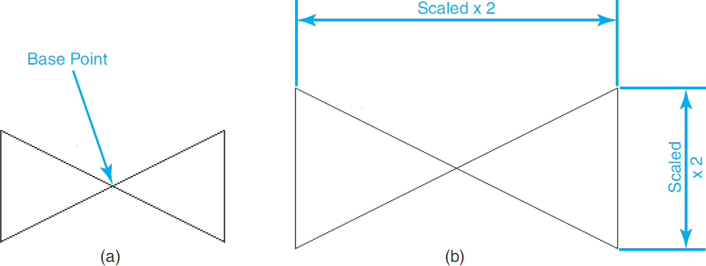
Figure 7-39 A Objects before scaling B Objects scaled by a factor of 2
The Reference option allows you to scale objects by specifying a reference, or start length, and then a new, absolute length to scale to. AutoCAD determines the necessary scale factor by calculating the difference between the reference length and the new length.
After you select the Reference option, you can either type in a length via the keyboard, or you can select two points in your drawing that define the reference length. The Reference option is invaluable if you don’t know the length of an existing object but you do know the length it needs to be. Using object snaps, you can snap to two points on the object(s) that define its current length, as shown in Figure 7-40.
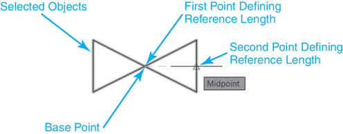
Figure 7-40 Scaling objects using the Reference option—Start length
AutoCAD then prompts you to Specify new length or ![]() . You can either type in a length via the keyboard, or you can use the Points option to select two points in the drawing to define the new length as shown in Figure 7-41.
. You can either type in a length via the keyboard, or you can use the Points option to select two points in the drawing to define the new length as shown in Figure 7-41.
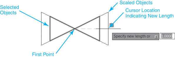
Figure 7-41 Scaling objects using the Reference option—New length
Scaling and Copying Objects
It is possible to scale and copy object(s) using the Copy option. Using the Copy option, AutoCAD displays the following at the command line:
Scaling a copy of the selected objects.
You can use any of the methods explained earlier to specify a scale factor.
Tip
AutoCAD remembers the scale factor entered using any of the SCALE command options so that it is now the default scale factor. The next time you use the SCALE command, you can press <Enter> and scale by the same factor again.
Exercise 7-13 Scaling Objects
![]() Continue from Exercise 7-12.
Continue from Exercise 7-12.
![]() Start the SCALE command, and select both triangles using your preferred selection method so that AutoCAD prompts Specify base point or
Start the SCALE command, and select both triangles using your preferred selection method so that AutoCAD prompts Specify base point or ![]() .
.
![]() Snap to the intersection of both triangles using the Intersection object snap, as shown in Figure 7-38. AutoCAD prompts Specify scale factor or
Snap to the intersection of both triangles using the Intersection object snap, as shown in Figure 7-38. AutoCAD prompts Specify scale factor or ![]() .
.
![]() Scale the triangles to any scale using a cursor pick point, as shown in Figure 7-38.
Scale the triangles to any scale using a cursor pick point, as shown in Figure 7-38.
![]() Type U<Enter> or select the Undo tool so that the triangles are scaled to their original size again, as shown in Figure 7-39A.
Type U<Enter> or select the Undo tool so that the triangles are scaled to their original size again, as shown in Figure 7-39A.
![]() Start the SCALE command again, and select the triangles using your preferred selection method so that AutoCAD prompts Specify base point or
Start the SCALE command again, and select the triangles using your preferred selection method so that AutoCAD prompts Specify base point or ![]() .
.
![]() Snap to the intersection of both triangles using the Intersection object snap, as shown in Figure 7-38. AutoCAD prompts Specify scale factor or
Snap to the intersection of both triangles using the Intersection object snap, as shown in Figure 7-38. AutoCAD prompts Specify scale factor or ![]() .
.
![]() Type 2<Enter>. The triangles are scaled up by a factor of 2, as shown in Figure 7-39B.
Type 2<Enter>. The triangles are scaled up by a factor of 2, as shown in Figure 7-39B.
![]() Type U<Enter> or select the Undo tool so that the triangles are scaled to their original size again, as shown in Figure 7-39A.
Type U<Enter> or select the Undo tool so that the triangles are scaled to their original size again, as shown in Figure 7-39A.
Stretching Objects
The STRETCH command moves or stretches objects a user-supplied distance and angle using the crossing window or crossing polygon selection option. The key to the STRETCH command is that it moves only endpoints and vertices that lie inside the crossing selection, leaving those outside unchanged.
Stretch |
|
|---|---|
Ribbon & Panel: |
Home | Modify |
Menu: |
Modify | Stretch |
Command Line: |
STRETCH |
Command Alias: |
S |
When you start the STRETCH command, AutoCAD displays the following at the command line:
Select objects to stretch by crossing-window or crossing-polygon...
AutoCAD also prompts you to Select objects:. You must select the object(s) you want to stretch using either the Crossing or Crossing Polygon selection option, as shown in Figure 7-42.
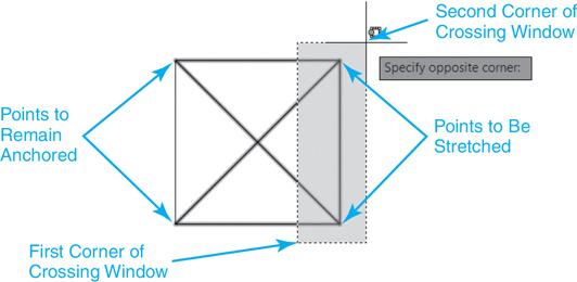
Figure 7-42 Selecting objects to stretch using a crossing selection
AutoCAD then prompts you to Specify base point or ![]() . You have three options:
. You have three options:
![]() Specify a base point.
Specify a base point.
![]() Select the Displacement option.
Select the Displacement option.
![]() Enter a displacement distance using Cartesian coordinates.
Enter a displacement distance using Cartesian coordinates.
Tip
You can use standard object selection methods such as picking on the object, and AutoCAD automatically treats those objects with a move operation. You can also apply multiple crossing selections within a single stretch operation to stretch multiple object selections simultaneously.
Using the first option, you typically pick a base (from) point by snapping to a key object feature using an object snap. You can then pick a destination (to) point, and the selected objects are stretched or moved to the new location, as shown in Figure 7-43.
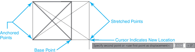
Figure 7-43 Stretching objects using mouse pick points
Notice in Figure 7-43 that the STRETCH command leaves any points or vertices outside the crossing selection anchored in place so that they are unaffected by the move. This is useful when you need to move or stretch part of a drawing but leave other portions of the drawing intact.
In the example above, you can also rely on direct distance entry to locate the second point. Using direct distance, you simply point the direction you want to stretch the selected object(s) and type in the distance you want to travel.
Note
It is also possible to type a base point as a Cartesian coordinate value at the cursor or the command line. You can then specify a destination point either by using your mouse or by entering an absolute, relative, or polar coordinate value.
Tip
Remember that the best way to utilize direct distance entry is to use it in conjunction with either Polar Tracking or Ortho Mode. Using either of these drawing tools allows you to lock in an angle and enter a distance for precise movement.
The Displacement option allows you to specify a displacement distance using rectangular or polar coordinates. The coordinate value you enter is always the relative distance the selected object(s) will be stretched, even if you omit the @ sign.
After you select the Displacement option, you can enter the displacement distance using either rectangular (x,y) or polar (@distance<angle) coordinates. Entering 2,0<Enter> results in the stretch operation shown in Figure 7-44.
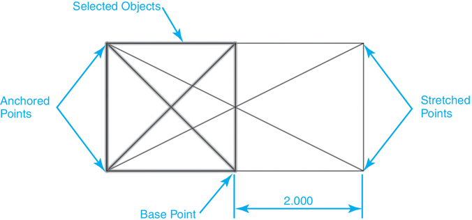
Figure 7-44 Stretching objects using the Displacement option
Tip
AutoCAD remembers the displacement distance entered so that it is now the default distance. The next time you use the STRETCH command, you can just press <Enter> to stretch the same distance again.
The third option is a shortcut to the Displacement option explained previously. It is possible to enter a Cartesian coordinate displacement distance directly in response to the first Specify base point or ![]() prompt explained earlier. Entering an x,y distance and pressing <Enter> twice selects the default <use first point as displacement> option so that the x,y distance entered is used as the displacement distance.
prompt explained earlier. Entering an x,y distance and pressing <Enter> twice selects the default <use first point as displacement> option so that the x,y distance entered is used as the displacement distance.
Exercise 7-14 Stretching Objects
![]() Continue from Exercise 7-13.
Continue from Exercise 7-13.
![]() Erase any existing line work in your drawing from previous exercises.
Erase any existing line work in your drawing from previous exercises.
![]() Draw a 2″×2″ square with a cross similar to the one shown in Figure 7-42.
Draw a 2″×2″ square with a cross similar to the one shown in Figure 7-42.
![]() Start the STRETCH command, and select the line endpoints on the right side of the square using the Crossing selection method shown in Figure 7-42 so that AutoCAD prompts Specify base point or
Start the STRETCH command, and select the line endpoints on the right side of the square using the Crossing selection method shown in Figure 7-42 so that AutoCAD prompts Specify base point or ![]() .
.
![]() Snap to the lower-right corner of the square using the Endpoint object snap, as shown in Figure 7-43. AutoCAD prompts Specify second point or <use first point as displacement>:.
Snap to the lower-right corner of the square using the Endpoint object snap, as shown in Figure 7-43. AutoCAD prompts Specify second point or <use first point as displacement>:.
![]() Stretch the line endpoints to the right using a second pick point, as shown in Figure 7-43.
Stretch the line endpoints to the right using a second pick point, as shown in Figure 7-43.
![]() Type U<Enter> or select the Undo tool so that the square is its original size.
Type U<Enter> or select the Undo tool so that the square is its original size.
![]() Start the STRETCH command, and select the line endpoints on the right side of the square using the Crossing selection method shown in Figure 7-42 so that AutoCAD prompts Specify base point or
Start the STRETCH command, and select the line endpoints on the right side of the square using the Crossing selection method shown in Figure 7-42 so that AutoCAD prompts Specify base point or ![]() .
.
![]() Type 2,0<Enter>. AutoCAD prompts Specify second point or <use first point as displacement>:.
Type 2,0<Enter>. AutoCAD prompts Specify second point or <use first point as displacement>:.
![]() Press <Enter> again to use the first point entered as the displacement distance. The square is stretched +2 units on the X-axis as shown in Figure 7-44.
Press <Enter> again to use the first point entered as the displacement distance. The square is stretched +2 units on the X-axis as shown in Figure 7-44.
![]() Type U<Enter> or select the Undo tool so that only one square is left in its original location.
Type U<Enter> or select the Undo tool so that only one square is left in its original location.
Selecting Objects First
Now that you have seen how to modify objects using the traditional verb/noun approach of selecting a modify command and then the objects to modify, let’s look at the noun/verb approach of selecting objects first and then selecting a modify command. First, make sure that the Noun/verb selection check box is selected on the Selection tab of the Options dialog box, as shown in Figure 7-2. It is on by default.
Tip
The PICKFIRST system variable can also be used to control the noun/verb selection setting. Setting PICKFIRST to 1 (on) is the same as selecting the Noun/verb selection check box. Setting PICKFIRST to 0 (off) turns off the Noun/verb selection check box.
Using noun/verb selection, you can select objects either by using your cursor or by using implied windowing to create a lasso, a window, or a crossing selection. When you select objects first using implied windowing, you have additional options. After selecting the first point in a clear area of the drawing so you avoid selecting an object directly, it is possible to select the Fence, WPolygon, or CPolygon option in addition to defining a two-point rectangular window area. Selected objects are highlighted, and if grips are enabled, their grips are turned on as shown in Figure 7-45. Grips are explained in detail in the next section. If you now select any of the modify commands introduced in this chapter, the selected objects become the default selection set for the modify command, and you are not prompted to select any objects. You can then use the command and any command options by applying the same techniques explained in the previous sections.
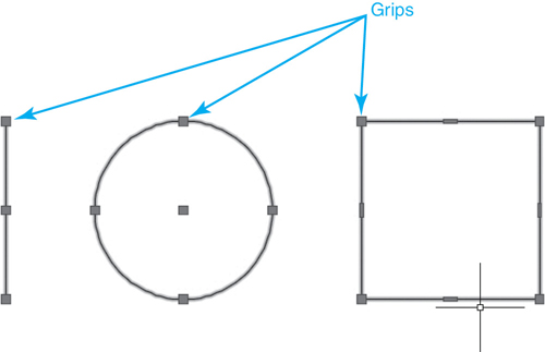
Figure 7-45 Grips displayed for a line, circle, and rectangle
Note
Setting the PICKAUTO system variable to 2 allows you to start an implied window even while picking directly on an object, minimizing the need to find a clear area of your drawing.
Exercise 7-15 Selecting Objects First for Editing
![]() Continue from Exercise 7-14.
Continue from Exercise 7-14.
![]() Select all the objects in the drawing either by selecting objects individually with your mouse or by using implied windowing.
Select all the objects in the drawing either by selecting objects individually with your mouse or by using implied windowing.
![]() Select the ERASE command. All the objects are erased.
Select the ERASE command. All the objects are erased.
Using Grips to Edit
Grips are the small colored squares (default = blue) that appear at key object definition points when an object is selected, as shown in Figure 7-45.
Grips act as object handles and when selected provide quick, easy access to the five basic modify commands, explained earlier in this chapter, so that you can maintain your focus on your drawing. The five grip commands, or modes, are as follows:
![]() Stretch
Stretch
![]() Move
Move
![]() Rotate
Rotate
![]() Scale
Scale
![]() Mirror
Mirror
Multifunctional Grips
Some AutoCAD objects, such as lines, arcs, and dimensions, have grips that can perform multiple functions. Hovering your cursor over a grip displays a shortcut menu similar to those shown in Figure 7-46 so you can select the desired command using your mouse or the arrow key on your keyboard.
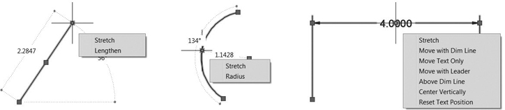
Figure 7-46 Multifunctional grips
TIP
After a grip is selected using the techniques described in the following sections, you can cycle through any available multifunctional grips by pressing the <Ctrl> key.
Controlling Grips
Grips are controlled on the Selection tab of the Options dialog box shown in Figure 7-47.
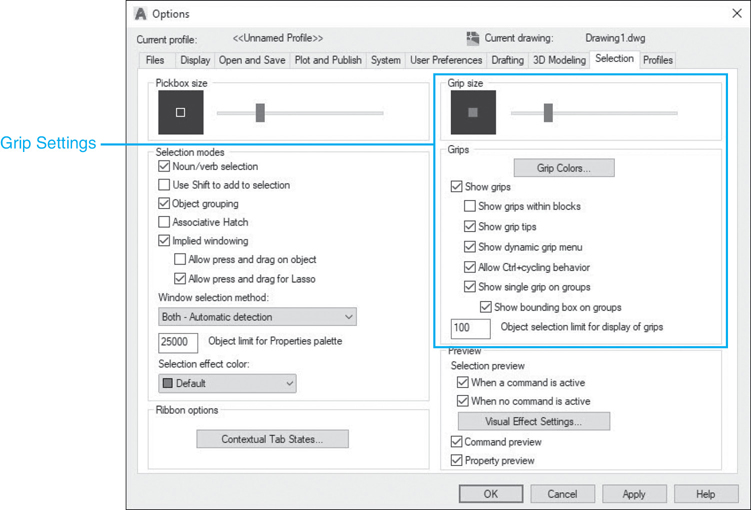
Figure 7-47 Grip settings on the Selection tab of the Options dialog box
The different grip features and their settings are as follows:
Grip size Controls the display size of grips
Grip Colors... Determines the color of grips in various modes
Show grips Displays grips on an object when it is selected
Show grips within blocks Controls how grips are displayed on a block after you select it. If this option is selected, AutoCAD displays all grips for each object in the block. If this option is cleared, AutoCAD displays one grip located at the insertion point of the block
Show grip tips Displays grip-specific tips when the cursor hovers over a grip on a custom object that supports grip tips. This option has no effect on standard AutoCAD objects
Show dynamic grip menu Controls the display of a dynamic menu when pausing over multifunctional grips used by polylines and splines
Allow Ctrl+cycling behavior Allows the <Ctrl> key cycling behavior for multifunctional grips used by polylines and splines
Show single grip on groups Displays a single grip for an object group
Show bounding box on groups Displays a bounding box around the extents of grouped objects
Object selection limit for display of grips Suppresses the display of grips when the initial selection set includes more than the specified number of objects. The valid range is 1 to 32,767. The default setting is 100.
For the best results, make sure that your grip settings closely match those shown in Figure 7-47. Failure to do so can cause some of the examples and exercises in the following sections to behave differently than anticipated.
Selecting Grips
To select a grip, you must place your cursor within the grip box and pick with your mouse. When a grip is selected, it changes color (default = red), and you are placed in Grip Edit mode, as shown in Figure 7-48.

Figure 7-48 One grip selected
It is possible to select multiple grips by holding down the <Shift> key before selecting the first grip. You can continue to select grips until you release the <Shift> key. In Figure 7-49, two grips have been selected.

Figure 7-49 Two grips selected
To “unselect” all grips that have been selected (default = red), as shown in Figure 7-48, press the <Esc> key once. This changes the grips to the unselected mode (default = blue), as shown in Figure 7-48. To turn off all the grips that are unselected (default = blue), you must press the <Esc> key again. This will result in the object(s) being simply highlighted with no grips displayed.
Tip
You can remove objects from the selection set by holding down the <Shift> key and selecting the object you want to remove.
Grip Modes
After at least one grip is selected (default = red) and you are in Grip Edit mode, as shown in Figure 7-49, the desired grip mode can be selected either at the command line or via the right-click Grip shortcut menu.
The command line approach allows you to cycle through the five different grip modes starting with Stretch mode by pressing the spacebar or the <Enter> key as follows:
** STRETCH **
Specify stretch point or [Base point Copy Undo eXit]:
** MOVE **
Specify move point or [Base point Copy Undo eXit]:
** ROTATE **
Specify rotation angle or [Base point Copy Undo Reference eXit]:
** SCALE **
Specify scale factor or [Base point Copy Undo Reference eXit]:
** MIRROR **
Specify second point or [Base point Copy Undo eXit]:
Each time you press the spacebar or <Enter>, AutoCAD cycles to the next grip mode in the order shown above, repeating the modes again when it gets back to Stretch mode.
Tip
You can also type keyboard shortcuts to go directly to the desired grip mode option at the command line. The shortcuts are ST for Stretch, MO for Move, RO for Rotate, SC for Scale, and MI for Mirror.
The other option is to right-click with your mouse to display the Grip shortcut menu shown in Figure 7-50.
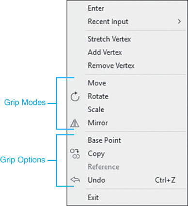
Figure 7-50 Grip shortcut menu
This approach allows you to go directly to the desired grip mode option without having to hit your spacebar or the <Enter> key multiple times.
Using either approach, the different grip modes work similarly to their traditional modify command counterparts, explained earlier in the chapter, and share most of the same options. Each grip mode shares the following options:
Base Point Allows you to specify a new base point to use with the current grip mode. By default, the base point is set to the selected grip
Copy Allows you to create a copy of the selected object(s) to use with the current grip mode
Undo Undoes the last grip mode operation
Exit Exits the current grip mode and leaves grips on but unselected
In addition, the Rotate and Scale modes also have a Reference option that works exactly the same as described earlier in the ROTATE and SCALE modify command sections.
After selecting the desired grip mode either at the command line or via the Grip shortcut menu, the different grip mode options can be selected by selecting the first letter of the option at the command line, by selecting the option from the right-click shortcut menu, or by using your arrow keys if you are using dynamic input.
Chapter Summary
This chapter presents the basics of selecting and modifying objects in an AutoCAD drawing. The different object selection techniques explored in this chapter can be applied throughout the rest of the text. As you can see, there are many different ways to go about creating and modifying a selection set. Practice using, and even combining, the different selection and editing techniques and try to think “outside of the box.” Sometimes you might want to pick objects first and then select a modify command; other times it makes sense to pick a command first and then the objects(s) to modify. If a collection of objects is to be used repeatedly, try grouping them together using the AutoCAD group tools so they behave as one unit.
You will use many of the basic modify commands introduced in this chapter on a daily basis. They form the basis of most of the editing that occurs in a drawing. Note that most of the modify tools work similarly and display the same prompts. This is so you can apply the knowledge learned mastering one tool across the range of modify tools and become a more productive drafter.
Grips are just another way of doing the same thing: modifying drawing information. They are quicker for simple operations but may be more tedious for other, more complex tasks. Some of the things you can do with grips and dynamic input cannot be done as quickly any other way. Conversely, multifunctional grips can provide the quickest access to an object-specific command. It is all a matter of picking the right tool for the job. Experience is the best way to figure out which tool you should reach for in any given situation.
Chapter Test Questions
Multiple Choice
Circle the correct answer.
1. Selecting objects first and then selecting a modify command is referred to as what type of editing process?
a. Noun/verb
b. Verb/noun
c. Grip mode
d. Cut and paste
2. A selection set is:
a. A set of commands used to select objects
b. All currently selected objects
c. A group of similar objects
d. None of the above
3. The box that appears at the mouse crosshairs when you are prompted to select objects is called:
a. Grip
b. Aperture
c. Pickbox
d. Window area
4. When you are creating a selection set, you can remove objects by:
a. Typing U<Enter>
b. Holding down the <Shift> key while selecting objects
c. Entering Remove object mode by typing R<Enter>
d. All of the above
5. The difference between the window selection method and the crossing selection method is:
a. A window boundary is a solid line, and a crossing boundary is a dashed line
b. The window method selects only objects inside the boundary, and the crossing method selects objects inside and objects that cross the boundary
c. By default, the window area preview is blue, and the crossing area preview is green
d. All of the above
6. Implied windowing allows you to:
a. Automatically create a window, crossing, or lasso selection
b. Turn off window, crossing, and lasso selection options
c. Turn on window, crossing, and lasso selection options
d. Select objects with your mind
7. The system variable that controls whether text is reversed when it is mirrored is:
a. MIRRORTEXT
b. MIRRTEXT
c. TEXTMIRROR
d. MTEXT
8. To select multiple grips, you must hold down which key when picking the first grip?
a. <Ctrl>
b. <Shift>
c. <Esc>
d. Spacebar
9. Grip modes can be selected via:
a. Command line
b. Right-click shortcut menu
c. Keyboard shortcuts
d. All of the above
10. The keyboard key that turns off (deselects) grips is:
a. <Ctrl>
b. <Enter>
c. <Esc>
d. <Alt>
Matching
Write the number of the correct answer on the line.
a. ERASE command ______ |
1. Automated window, crossing, or lasso selection option |
b. Selection set ______ |
2. Moves objects a user-supplied distance and angle |
c. Implied window ______ |
3. Creates a mirror image of objects about a mirror axis line |
d. Grips ______ |
4. Small squares that appear when an object is selected |
e. MOVE command ______ |
5. Removes objects from a drawing |
f. COPY command ______ |
6. Rotates objects a user-specified rotation angle around a user-specified base point |
g. MIRROR command ______ |
7. Moves or stretches objects a user-supplied distance and angle |
h. ROTATE command ______ |
8. Scales objects a user-specified scale factor about a user-specified base point |
i. SCALE command ______ |
9. Copies objects a user-supplied distance and angle |
j. STRETCH command ______ |
10. Group of one or more objects selected in a drawing |
True or False
Circle the correct answer.
1. True or False: The traditional approach to modifying objects in AutoCAD is to select the command first and then select the objects to modify.
2. True or False: The traditional approach to modifying mentioned in question 1 is referred to as the noun/verb approach.
3. True or False: It is possible to select more than one grip at a time using the <Shift> key.
4. True or False: The window, crossing, and lasso selection options can be initiated automatically.
5. True or False: It is possible to create a window, crossing, or lasso selection using only one pick point.
6. True or False: The Previous selection option will select the previous object that was added to a drawing.
7. True or False: The displacement distance for the MOVE, COPY, and STRETCH commands is always relative.
8. True or False: Text is always mirrored when you use the MIRROR command.
9. True or False: It is possible to enter a negative rotation angle when using the ROTATE command.
Chapter Projects
 Project 7-1: Classroom Plan, continued from Chapter 6 [BASIC]
Open drawing P6-1 from Chapter 6.
Draw the floor plan shown in Figure 7-51 using the A-Door and A-Wall layers for the doors and walls. Place the heater on the A-Eqpm layer. The wall next to the heater is 8″ thick; all other walls are 4″ thick. The doors are each 3″-0″ wide, and the heater is 1″-0″ wide. Do not draw dimensions or text.

Figure 7-51
Use the MOVE, COPY, and MIRROR commands to place the desks in the configuration shown. Use object snaps and the Polar Tracking and/or Ortho Mode settings to ensure the desks are aligned.
Save the drawing as P7-1.
 Project 7-2: Socket Head Cap Screws— English Units [INTERMEDIATE]
Start a new drawing using the acad.dwt template.
Create two socket head cap screws based on the table shown in Figure 7-52. Do not draw dimensions or table.
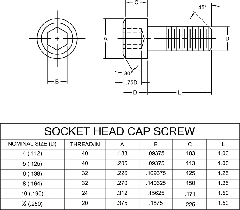
Figure 7-52
Save the drawing as P7-2.
Project 7-3: Motorcycle Head Gasket— Metric [ADVANCED]
Start a new drawing using the acadiso.dwt template.
Create the following layers:
Name
Color
Linetype
Lineweight
Description
Object
7
Continuous
0.60 mm
Object lines
Hidden
1
Hidden
0.30 mm
Hidden lines
Center
2
Center
0.30 mm
Centerlines
Hatch
4
Continuous
0.30 mm
Hatch patterns and fills
Notes
3
Continuous
0.30 mm
Text and notes
Dims
2
Continuous
0.30 mm
Dimensions
Draw the motorcycle head gasket shown in Figure 7-53 using the appropriate layers.

Figure 7-53
Adjust the LTSCALE system so linetypes appear properly.
Do not include dimensions.
Save the drawing as P7-3.
 Project 7-4: Electrical Distribution Panel [BASIC]
Start a new drawing using the acad.dwt template.
Create the following layer:
Name
Color
Linetype
Lineweight
Plot/Noplot
Description
E-Powr-Panl
7
Continuous
Default
Plot
Electrical power panels
Set the grid to .5 and the snap to .25, and draw the electrical distribution panel shown in Figure 7-54. Do not draw grid lines. Hint: The grid lines shown are spaced at .5 intervals.

Figure 7-54
Save the drawing as P7-4.
 Project 7-5: Residential Architectural Plan, continued from Chapter 6 [ADVANCED]
Open drawing P6-5 from Chapter 6.
Draw the door and window symbols shown in Figure 7-55 using the A-Door and A-Glaz layers.
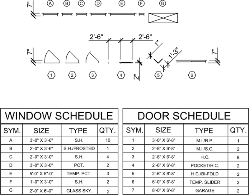
Figure 7-55
Add the walls and place the doors and windows as shown in Figure 7-56 according to the schedules. Use appropriate object snaps to ensure the proper placement of the symbols. Doors and windows that are not dimensioned are either centered on the interior wall or located 3″ from the nearest wall. Hint: Use the Offset option of the XLINE command to locate the door and window symbols.

Figure 7-56
Do not draw the door schedule or identifier symbols. Do not draw dimensions or text.
Save the drawing as P7-5.