Appendix A: Drafting Standards Overview
Standards Organizations
Standards provide a basis for uniformity in engineering drawing. Many industries and governments can use these standards as a guideline to develop their documents. It is not the intent of recognized national standards organizations to prevent individual organizations from designing specific formats. The intent is to provide common engineering standards to aid the interchange of drawings among companies, governments, and other users.
The following organizations are three leaders in drafting standards.
American National Standards Institute (ANSI)
ANSI has been a leader in the voluntary standards system of the United States. This organization has provided a forum for private and public sectors to collectively work together toward the development of national standards. Efforts to coordinate national standards date back to 1911. In 1916, the following agencies were instrumental in establishing a national body to oversee the development of national standards:
![]() The American Institute of Electrical Engineers (now IEEE)
The American Institute of Electrical Engineers (now IEEE)
![]() The American Society of Mechanical Engineers (ASME)
The American Society of Mechanical Engineers (ASME)
![]() The American Society of Civil Engineers (ASCE)
The American Society of Civil Engineers (ASCE)
![]() The American Institute of Mining, Metallurgical, and Petroleum Engineers (AIME)
The American Institute of Mining, Metallurgical, and Petroleum Engineers (AIME)
![]() The American Society for Testing and Materials (ASTM)
The American Society for Testing and Materials (ASTM)
These organizations along with the U.S. Departments of War, Navy, and Commerce were the founders of the American Engineering Standards Committee (AESC). This organization led to the formation of the American National Standards Institute (ANSI) in 1969. Throughout its history, ANSI has continued to coordinate national and international efforts to approve voluntary standards. Over the past 85 years, this organization has maintained its strong ties with the original founding organizations and others to become one of the most highly regarded standards systems in the world.
Specific standards are revised periodically by a committee of industry leaders who also serve as representatives of various industry service organizations. For example, the vice president of engineering at Xerox Corporation might serve on the board of the American Society of Mechanical Engineers (ASME). These committee members revise such standards as Drawing Sheet Size and Format, Dimensioning and Tolerancing, and Line Conventions and Lettering. The standards should be readily available in the classroom so that students can develop engineering drawings that adhere to these standards. Specific standards must be available for each content area—mechanical, electrical, or civil. The following section lists some commonly used mechanical engineering standards.
American Society of Mechanical Engineers (ASME)
The American Society of Mechanical Engineers conducts one of the world’s largest publishing operations to produce technical and engineering documents to establish standards. ASME documents are recognized worldwide for industrial and manufacturing codes and standards. Some of the popular documents on engineering standards include:
Y14.2M-1992 Line Conventions and Lettering
Y14.5.2-2000-2001 Certification of Geometric Dimensioning and Tolerancing
Y14.38-1999 Abbreviations and Acronyms
Y14.1-1980 (R1987) Drawing Sheet Size and Format
Y14.1M-1992 Metric Drawing Sheet Size and Format
Y14.3M-1994 Multiview and Sectional View Drawings
International Organization for Standardization (ISO)
The International Organization for Standardization is an organized network of the national standards institutes of 148 countries. It is a nongovernmental organization, but its members are not. ISO has a unique mission in acting as a bridge between business/industry and consumers/users. ISO has published more than 13,700 International Standards ranging from engineering drawing to medical devices. ISO is also responsible for providing a framework for quality management throughout the processes of producing and delivering products and services by implementing ISO 9000.
Some of the more commonly used ISO drawing standards are:
ISO 10135:1994
Technical drawings—Simplified representation of molded, cast, and forged parts
ISO 10209-1:1992
Technical product documentation—Vocabulary—Part 1: Terms relating to technical drawings: general and types of drawings
ISO 10209-2:1993
Technical product documentation—Vocabulary—Part 2: Terms relating to projection methods
Many companies, such as General Electric and General Motors, develop their own standards by incorporating the use of ANSI, ASME, and ISO criteria. In this way, national standards can be incorporated with company standards to meet specific requirements.
Text
Text can be inserted into the model space or into paper space layouts. When inserting text into a layout, the height of the text is equal to the printed or plotted size. Layouts are normally printed or plotted on a one-to-one scale. If the text height is inserted at 0.125 into the layout and printed at 1:1, the printed text height will be 0.125.
When text is entered into model space, consideration must be given to the drawing scale factor. See the following section for additional information about standard model space text heights.
Standard Text Heights
The typical standard height for text on a drawing is 1/8″. Fractions need to be created 1/4″ tall. These are general guidelines for text height. Text height should be increased or decreased based on individual situations.
To achieve these final printed and plotted text sizes, it is necessary to create the text within the AutoCAD drawing at the correct size. The following table lists examples of the relationship between sheet size, plot scale, scale factor, model space drawing area, and text height.
Appendix A Drafting Standards Overview |
|||||
|---|---|---|---|---|---|
|
Sheet Size |
Plot Scale |
Scale Factor |
Model Space Drawing Area |
Text Height |
Architect’s Scale |
12″ × 9″ |
1/8″ = 1′-0″ |
96 |
96′ × 72′ |
1′-0″ |
|
24″ × 18″ |
1/2″ = 1′-0″ |
24 |
48′ × 36′ |
3″ |
Engineer’s Scale (Civil) |
18″ × 12″ |
1″ = 200′ |
2400 |
3600′ × 2400′ |
25′ |
|
36″ × 24″ |
1″ = 50′ |
600 |
1800′ × 1200′ |
6.25′ |
Engineer’s Scale (Mech.) |
11″ × 8.5″ |
1″ = 2″ |
2 |
22″ × 17″ |
.25″ |
|
34″ × 22″ |
1″ = 1.5″ |
1.5 |
51″ × 33″ |
3/16″ |
Metric Scale |
279 mm × 216 mm |
1 mm = 5 mm |
5 |
1395 mm × 1080 mm |
15.875 mm |
|
432 mm × 279 mm |
1 mm = 20 mm |
20 |
7620 mm × 5080 mm |
63.5 mm |
Calculating the Scale Factor
The drawing scale factor used to scale annotation features up and down is always the reciprocal of the plot or viewport scale. The easiest way to calculate the reciprocal value of the plot/viewport scale is to first put all values into the same units and then cross-multiply. For example, to calculate the drawing scale factor for the architect’s scale 1/8″ = 1′-0″, you would first convert all values to inches and display them all as stacked fractions:
Then cross-multiply by multiplying the denominator on the left side of the equal sign (=) (8) times the numerator on the right side (12) and then the numerator on the left (1) times the denominator on the right (1) for a result of 96/1. The last step is to reduce the fraction by dividing the denominator (1) into the numerator (96) for a scale factor of 96.
Notes and Locating Text on a Drawing
Notes and text are necessary to supplement a fully dimensioned engineering drawing. Notes should be clear and concise to avoid any misinterpretation. Notes are always lettered horizontally on the sheet and systematically organized. Do not place notes and text in crowded or busy locations on the drawing. Avoid placing notes between orthographic views. Use only standard ANSI or ASME abbreviations with a note.
Notes are classified as General Notes or Local/Specific Notes.
General Notes. General notes apply to the entire drawing. General notes are typically placed in the lower right corner of the drawing above or to the left of the title block. Title blocks may provide general information about the drawing such as tolerance, material, or treatment. General notes may be placed below the view to which the note applies.
Local/Specific Notes. Local notes provide specific detailed information. These notes are placed adjacent to the specific feature they describe. Local notes may be connected with a leader. The leader arrow or dot will touch the detail and end with a note.
Leaders
Leaders should be attached at the middle front of the first word of the note or after the last word of the note. Leaders to a circle should be developed radially. The slanted line of the leader should be aimed at the center of the circle or arc. A shoulder or horizontal line of the leader is optional. Leader lines should not cross each other. Refer to the following standard for additional information:
Y14.5.2-2000-2001 Certification of Geometric Dimensioning and Tolerancing
Sheet Layouts
A convenient code to identify American National Standard sheet sizes and forms suggested by the authors for title, parts or materials list, and revision blocks, for use of instructors in making assignments, is shown here. All dimensions are in inches.
Three sizes of sheets are illustrated: Size A, Figure A-1; Size B, Figure A-5; and Size C, Figure A-6. Metric size sheets are not shown.

Figure A-1 Size A sheet (8.50″ × 11.00″)
Eight forms of lettering arrangements are suggested, known as Forms 1, 2, 3, 4, 5, 6, 7, and 8, as shown below and on the next page (see Figures A-2, A-3, A-4, A-7, A-8, and A-9). The total length of Forms 1, 2, 3, and 4 may be adjusted to fit Sizes A4, A3, and A2.
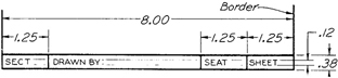
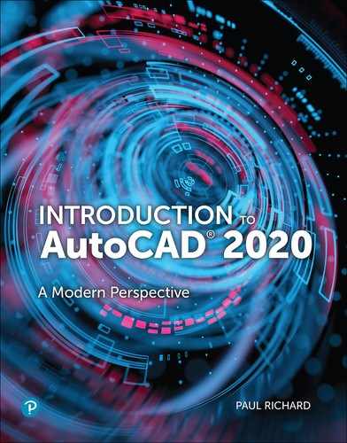
Figure A-2 Form 1. Title block

Figure A-3 Form 2. Title block

Figure A-4 Form 3. Title block

Sheet Sizes
American National Standard
A – 8.50″ × 11.00″
B – 11.00″ × 17.00″
C – 17.00″ × 22.00″
D – 22.00″ × 34.00″
E – 34.00″ × 44.00″
International Standard
A4 – 210 mm × 297 mm
A3 – 297 mm × 420 mm
A2 – 420 mm × 594 mm
A1 – 594 mm × 841 mm
A0 – 841 mm × 1189 mm
(25.4 mm 5 1.00″)
Figure A-5 Size B sheet (11.00″ × 17.00″)

Figure A-6 Size C sheet (17.00″ × 22.00″)
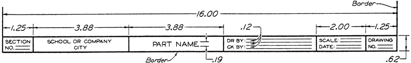
Figure A-7 Form 4. Title block

Figure A-8 Form 5. Title block
The term layout designates a sheet of a certain size plus a certain arrangement of lettering. Thus Layout A–1 is a combination of Size A, Figure A-1, and Form 1, Figure A-2. Layout C–678 is a combination of Size C, Figure A-6, and Forms 6, 7, and 8, Figures A-9, A-10, and A-11. Layout A4–2 (adjusted) is a combination of Size A4 and Form 2, Figure A-3, adjusted to fit between the borders. Other combinations may be employed as assigned by the instructor.
Figure A-9 Form 6. Title block
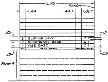
Figure A-10 Form 7. Parts list or materials list
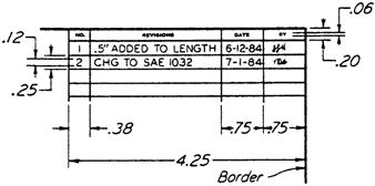
Figure A-11 Form 8. Revision block
Dimensions
The views of an object will describe the shape. The size of the object is described by the use of modern dimensioning techniques. It is important that an engineering drawing have accurate and functional dimensions.
Standard Feature Sizes
Figure A-12 illustrates some common terms and distances to consider when dimensioning standard feature sizes.

Figure A-12 Linear dimension features
Mechanical Style versus Architectural Style
Mechanical Style
There are two systems of placing dimensions on a drawing: the unidirectional system and the aligned system. In the unidirectional system, all the dimension figures and notes are lettered horizontally on the sheet (see Figure A-12). This is the preferred system of the American National Standards Institute. The mechanical style of dimensioning illustrates the unidirectional system. The unidirectional system is widely used because it is easy to read and interpret on large drawings. The unidirectional system is the standard default dimensioning system in AutoCAD.
Architectural Style
The architectural style of dimensioning (see Figure A-13) illustrates the aligned system. The aligned system has all the dimension figures aligned with the dimension line. Many of the dimension figures are horizontal on the sheet and some are aligned or turned. Any rotated figures are to be read from the right side of the sheet.
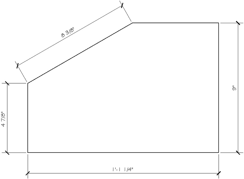
Figure A-13 Architectural dimension style
The architectural style of dimensioning has numbers placed on top of an unbroken dimension line. The dimension line typically ends with a slash, dot, or arrowhead. The numbers normally are designated with inch (″) and foot (′) symbols.
Linetypes and Thicknesses
Linetypes that are used within AutoCAD should correspond with the standard ANSI linetypes and thicknesses. Every line that is used on a technical drawing has a specific meaning and needs to be illustrated in a certain way. The American National Standards Institute has established the Line Conventions and Lettering standard ANSI Y-14.2M-1992. This standard describes the size, application, and construction of various lines that are used in creating engineering drawings. Figure A-14 details various linetypes and their applications.

Figure A-14 Alphabet of lines (full-size)
It should be noted that the line widths established in this illustration are approximate, and the actual width is governed by the size and style of the drawing. Large drawings will need to have wider lines, and drawings that are reduced in size will need to have smaller line widths than specified in this illustration. The ANSI Y-14.2M standard and this illustration should be used as a guide to produce crisp and legible engineering drawings from AutoCAD.
Linetypes are described in an AutoCAD file called ACAD.LIN. These linetypes should be loaded into the AutoCAD drawing file and assigned correct lineweights that correspond with the ANSI standards. The AutoCAD command LTSCALE should be used to adjust the size of the linetypes to match the size of the drawing area in AutoCAD. Figure A-15 shows examples of AutoCAD’s standard linetypes, which are defined in the ACAD.LIN file.

Figure A-15 Standard AutoCAD linetypes
Standard Sheet Sizes and Scales
The use of standard sheet sizes and the uniform locations of the title block, revision block, and bill of materials provide definite advantages for engineering drawings. These advantages include readability, handling, filing, and reproduction. As drawings are shared between organizations and companies, an advantage is realized when information is located in the same location on all drawings.
Standard sheet size also provides consistency between hand-drawn and printer/plotter-created engineering drawings. Drawings that are created on printers can use standard engineering sheet sizes of 8.5″ × 11″ or 17″ × 11″. Drawings that are created with plotters that use rolls of various media need to be trimmed to final standard size such as 17″ × 22″ or 22″ × 34″. International sheet sizes based on millimeters would need to be trimmed to final standard size such as 420 mm × 594 mm or 594 mm × 841 mm. (See Figure A-16.)

Figure A-16 Standard U.S. and metric paper sizes
Standard Plot Scales
Each drafting discipline has plot scales that are commonly used within that discipline. The following table lists standard plot scales for the mechanical, architectural, and civil engineering disciplines. These are preferred plot sales; other plot scales may be used as needed. In all cases, the plot scale should be clearly indicated on the drawing.
Mechanical Scale |
Architect’s Scale |
Engineers’ Scale |
|---|---|---|
1:1 |
⅛″ = 1′-0″ |
½″ = 10′ |
1:2 |
¼″ = 1′-0″ |
1″ = 20′ |
1:4 |
½″ = 1′-0″ |
1″ = 30′ |
2:1 |
1″ = 1′-0″ |
1″ = 50′ |
4:1 |
1½″ = 1′-0″ |
1″ = 60′ |
10:1 |
3″ = 1′-0″ |
1″ = 100′ |
Specifying the Scale on a Drawing
For machine drawings, the scale indicates the ratio of the size of the drawn object to its actual size, irrespective of the unit of measurement used. The recommended practice is to letter full-size or 1:1; half-size or 1:2; and similarly for other reductions. Expansion or enlargement scales are given as 2:1 or 2:3; 3:1 or 3:3; 5:1 or 5:3; 10:1 or 10:3; and so on.
The various scale calibrations available on the metric scale and the engineers’ scale provide almost unlimited scale ratios. The preferred metric scale ratios appear to be 1:1, 1:2, 1:5, 1:10, 1:20, 1:50, 1:100, and 1:200.
Map scales are indicated in terms of fractions, such as scale , or graphically, such as ![]() .
.
Standard ANSI Hatch Patterns
Section Lining
Section-lining symbols (see Figure A-17) have been used to indicate specific materials. These symbols represent general material types only, such as cast iron, brass, and steel. Now, however, because there are so many different types of materials, and each has so many subtypes, a general name or symbol is not enough. For example, there are hundreds of different kinds of steel. Since detailed specifications of material must be lettered in the form of a note or in the title strip, the general-purpose (cast-iron) section lining may be used for all materials on detail drawings (single parts).
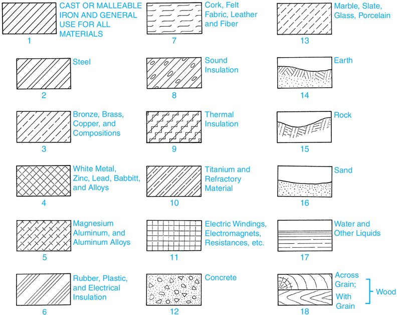
Figure A-17 Symbols for section lining
Section-lining symbols may be used in assembly drawings in cases where it is desirable to distinguish different materials; otherwise, the general-purpose symbol is used for all parts.
CAD programs usually include a library that allows the user to select from a variety of section-lining patterns, making it easy to indicate various types of material rather than using the generic cast-iron symbol for all sectioned parts.
ANSI has standardized many section lines that are used for sectional drawing. AutoCAD uses the HATCH command to insert hatch patterns that are used to illustrate these section lines. The following table lists the ANSI section line with corresponding AutoCAD hatch pattern, as seen in Figure A-17.
Figure Number |
ANSI Pattern Name |
AutoCAD Hatch Pattern |
|---|---|---|
A-17 (1) |
Cast/General Use |
ANSI 31 |
A-17 (2) |
Steel |
ANSI 32 or Steel |
A-17 (3) |
Bronze, brass, copper, etc. |
ANSI 33 |
A-17 (4) |
White metal, zinc, lead, etc. |
ANSI 37 |
A-17 (5) |
Magnesium, aluminum, etc. |
ANSI 38 (include a material note) |
A-17 (6) |
Rubber, plastic, electrical insulation |
ANSI 34 |
A-17 (7) |
Cork, felt, fabric, leather, fiber |
Cork |
A-17 (8) |
Sound insulation |
Insulation (include a material note) |
A-17 (9) |
Thermal insulation |
Insulation (include a material note) |
A-17 (10) |
Titanium/refractory material |
|
A-17 (11) |
Electric windings, electromagnets, etc. |
ANSI 37 (rotate 45°) |
A-17 (12) |
Concrete |
AR-CONC |
A-17 (13) |
Marble, slate, glass, porcelain |
Dash (rotate 45°) |
A-17 (14) |
Earth |
Earth (rotate angle) |
A-17 (15) |
Rock |
|
A-17 (16) |
Sand |
AR-SAND |
A-17 (17) |
Water and other liquids |
|
A-17 (18) |
Wood |
|
U.S. to Metric Units Conversions
AutoCAD provides some utilities for combining metric and imperial units within a single drawing. The following table lists standard U.S. (imperial) units of measurements and their metric conversions.
Length |
||
|---|---|---|
U.S. to Metric |
Metric to U.S. |
|
1 inch = 2.540 centimeters 1 foot = .305 meter 1 yard = .914 meter 1 mile = 1.609 kilometers |
1 millimeter = .039 inch 1 centimeter = .394 inch 1 meter - 3.281 feet or 1.094 yards 1 kilometer = .621 mile |
|
Area |
||
1 inch2 = 6.451 centimeter2 1 foot2 = .093 meter2 1 yard2 = .836 meter2 1 acre2 = 4,046.873 meter2 |
1 millimeter2 = .00155 inch2 1 centimeter2 = .155 inch2 1 meter2 = 10.764 foot2 or 1.196 yard2 1 kilometer2 = .386 mile2 or 247.04 acre2 |
|
Volume |
||
1 inch3 = 16.387 centimeter3 1 foot3 - .028 meter3 1 yard3 = .764 meter3 1 quart = 0.946 liter 1 gallon = .003785 meter3 |
1 centimeter3 = .061 inch3 1 meter3 - 35.314 foot3 or 1.308 yard3 1 liter = .2642 gallons 1 liter = 1.057 quarts 1 meter3 = 264.02 gallons |
|
Weight |
||
1 ounce = 28.349 grams 1 pound = .454 kilogram 1 ton = .907 metric ton |
1 gram = .035 ounce 1 kilogram = 2.205 pounds 1 metric ton = 1.102 tons |
|
Velocity |
||
1 foot/second = .305 meter/second 1 mile/hour = .447 meter/second |
1 meter/second = 3.281 feet/second 1 kilometer/hour = .621 mile/second |
|
Acceleration |
||
1 inch/second2 = .0254 meter/second2 1 foot/second2 = .305 meter/second2 |
1 meter/second2 = 3.278 feet/second2 |
|
Force |
||
N (newton) = basic unit of force, kg-m/s2. A mass of one kilogram (1 kg) exerts a gravitational force of 9.8 N (theoretically 9.80665 N) at mean sea level. |
||