Chapter Four: Basic Drawing Commands
Chapter Objectives
Create a new drawing
Establish the drawing units
Set the drawing limits
Create lines, circles, and arcs
Create ellipses and elliptical arcs
Create point objects, and control their size and appearance
Measure and divide using point objects
Introduction
The vast majority of 2D drawings are comprised of three basic drawing elements: lines, circles, and arcs. The size, location, color, line width, and line-type may vary. They may even be combined or joined together to create more complex objects. But most drawings can be broken down to these three basic elements. Chapter 2 gave you a quick introduction to these basic drawing objects. In this chapter, we’ll take a closer look at these basic drawing commands as well as ellipses and points. We’ll also examine some ways to control precisely the placement of AutoCAD objects and take a closer look at the various ways to create new drawings.
Drawing Setup
AutoCAD provides a number of ways to get started in a drawing. In Chapter 2, you used a drawing template to quickly start a new drawing with a number of preconfigured settings. Templates make starting a drawing quick and easy.
Templates
Drawing templates are simply drawings that have been set up and saved as templates with the file extension .dwt. AutoCAD comes with a number of predefined templates for various page sizes and industry standards. They typically have specific unit settings, title blocks, layer definitions, page layouts, dimension styles, and so on. The template acad.dwt is the default template. When you start a new drawing in AutoCAD, the blank drawing you see is created from the acad.dwt drawing template.
Any drawing can be saved as a template. To save a drawing as a template, choose Save as from the Quick Access toolbar, and choose AutoCAD Drawing Template to display the Save Drawing As dialog box (see Figure 4-1).
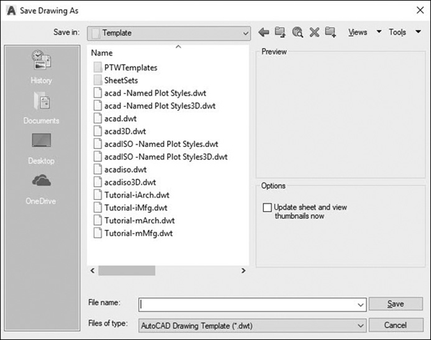
Figure 4-1 Creating a drawing template
By default, drawing templates are stored in a folder named Template that is created by AutoCAD.
Units |
|
|---|---|
Application Menu: |
Drawing Utilities |
Menu: |
Format | Units… |
Command Line: |
UNITS |
Command Alias: |
UN |

Tip
You can specify a different default template folder by changing the Default Template File Location setting under Template settings on the Files tab of the AutoCAD Options dialog box.
Units
Typically, the first step in setting up your drawing is to set the drawing units. Chapter 1 discussed the fact that AutoCAD is, for the most part, a unitless environment. One unit in AutoCAD can represent any measurement you want (1 inch, 1 foot, 1 millimeter, 1 meter, 1 nautical league, or even 1 parsec). The UNITS command allows you to control how AutoCAD displays units. It is located on the Drawing Utilities menu on the application menu (big A).
Note
The UNITS command controls only how units are displayed in the drawing. It does not control how geometry is stored nor does it control the precision of the geometry.
The UNITS command displays the Drawing Units dialog box (see Figure 4-2).
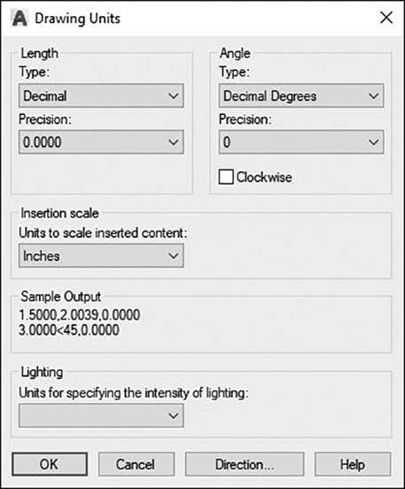
Figure 4-2 The Drawing Units dialog box
The Drawing Units dialog box allows you to set how both linear and angular measurements are displayed.
Linear Units. The Length settings control how linear units are displayed. You can choose from among five different linear unit display options: Decimal, Engineering, Architectural, Fractional, and Scientific. They are described in the following table.
Decimal |
This is the default format for displaying units. The Decimal setting is unitless in that decimal units can represent any unit of measurement. In general, you should note on your drawing which drawing units you are using. |
Engineering |
Engineering units are based on imperial feet-inch units. 1 unit is 1″, and 12 units are 1′. Inches are displayed in decimal units. For example, 15½″ would be displayed as 1″-3.5″. |
Architectural |
Architectural units are similar to engineering units except inches are displayed as fractions. For example, 15½″ would be displayed as 1″-3½″. |
Fractional |
Fractional units are similar to decimal units except that numbers are represented as fractions. For example, 15.5 units would display as 15½″. Like the Decimal setting, the Fractional setting is unitless. |
Scientific |
Scientific unit display uses exponential notation. For example, 15.5 would display as 1.5500E + 01 (1.55 × 101). Like the decimal and fractional unit displays, scientific unit display is unitless. |
Note
You can enter feet (′) and inches (″) only when drawing units are set to either Architectural or Engineering. If you try to enter either unit designation when drawing units are set to anything else, AutoCAD will reject the entry and display the following ambiguous message at the command line:
Point or option keyword required.
If you are using dynamic input, a bright red border is displayed around the distance input box, and you are forced to reenter a valid input value.
There is also a Precision: drop-down list that allows you to set the round-off setting for each unit type. The precision setting controls how precisely the number is displayed. The units are rounded off to the specified level of precision. It is important to note that this affects only how units are displayed on the screen. AutoCAD still stores numbers accurately; the numbers are simply rounded off when displayed on screen.
Angular Units. The Angle area controls how angles are input and displayed.
The Precision: drop-down list works the same for angular units as it does for linear units. The Clockwise check box allows you to change the direction that angles are measured. By default, angles are measured in a counterclockwise direction (see Figure 4-3).

Figure 4-3 Angular measurements
Decimal Degrees |
This is the default format for displaying angular measurements. 1 unit equals 1 degree. |
Deg/Min/Sec |
Degrees/Minutes/Seconds. With this format, there are 360 degrees in a full circle, 60 minutes in 1 degree, and 60 seconds in 1 minute. A 30-degree angle would display as 30d0′0″ where d denotes degrees, ′ denotes minutes, and ″ denotes seconds. Latitude and longitude are typically displayed using Deg/Min/Sec. |
Grads |
400 grads = 360 degrees. 1 grad is roughly 0.9 degree. |
Radians |
Radians are measured as multiples of pi (∏). 2 pi radians (∽6.28r) equals 360 degrees. Pi radian (3.14r) is 180 degrees. |
Surveyor´s Units |
Surveyor’s units show angles as bearings, using N or S for north or south, degrees/minutes/seconds to denote how far east or west the angle is from direct north or south, and E or W for east or west. For example, N 45d0′0″ E represents 45 degrees from north in the east direction (45 degrees in decimal units). Angles are always less than 90 degrees and are displayed in the Deg/Min/Sec format. You can simply use E, N, W, and S to represent 0, 90, 180, and 270 degrees, respectively. |
Putting a check in the Clockwise box changes the direction of angular measurement so that 90 degrees is south, and 270 degrees is north.
Exercise 4-1 Setting the Drawing Units
![]() Start a new drawing using the acad.dwt drawing template.
Start a new drawing using the acad.dwt drawing template.
![]() On the application menu, choose Units from the Drawing Utilities menu. The Drawing Units dialog box is displayed.
On the application menu, choose Units from the Drawing Utilities menu. The Drawing Units dialog box is displayed.
![]() In the Length area, choose Decimal from the Type: drop-down list and set the Precision to 0.00 (2 decimal places).
In the Length area, choose Decimal from the Type: drop-down list and set the Precision to 0.00 (2 decimal places).
![]() In the Angle area, choose Decimal Degrees from the Type: drop-down list and set the Precision to 0.0 (1 decimal place).
In the Angle area, choose Decimal Degrees from the Type: drop-down list and set the Precision to 0.0 (1 decimal place).
![]() Make sure there is no check in the Clockwise box and the Insertion scale is set to Inches. Choose OK to close the dialog box.
Make sure there is no check in the Clockwise box and the Insertion scale is set to Inches. Choose OK to close the dialog box.
![]() Save your drawing as CH04_EXERCISE.
Save your drawing as CH04_EXERCISE.
Setting the Drawing Area
AutoCAD provides an unlimited space for you to create your drawing. Chapter 1 discussed the concept of drawing objects their actual size. You’ll want to set up a large drawing area to draw large objects and a small drawing area to draw small ones. In model space, the drawing area is not critical and can be changed at any time. In layout (paper) space, the drawing area determines the paper size. The drawing area is set up using the LIMITS command in model space.
Limits |
|
|---|---|
Ribbon & Panel: |
None |
Menu: |
Format | Drawing Limits... |
Command Line: |
LIMITS |
Command Alias: |
None |
Note
The Zoom All command will zoom your drawing to fit the drawing area to your screen.
When you start the LIMITS command, AutoCAD will ask you to specify two points: the lower-left corner and the upper-right corner. These two corners determine the drawing area.
Exercise 4-2 Setting the Drawing Limits
![]() Continue from Exercise 4-1.
Continue from Exercise 4-1.
![]() Type limits<Enter>. AutoCAD prompts you to Specify lower-left corner or
Type limits<Enter>. AutoCAD prompts you to Specify lower-left corner or ![]() .
.
![]() Press <Enter> to accept the default setting of 0,0. AutoCAD then prompts you to Specify upper-right corner <12.00,9.00>:.
Press <Enter> to accept the default setting of 0,0. AutoCAD then prompts you to Specify upper-right corner <12.00,9.00>:.
![]() Type 11,8.5<Enter> to set the upper-right corner. You now have an 11 × 8.5 drawing area.
Type 11,8.5<Enter> to set the upper-right corner. You now have an 11 × 8.5 drawing area.
![]() Save your drawing.
Save your drawing.
Drawing Lines
In Chapter 2, we used the LINE command to create some simple geometric shapes. Lines are one of the fundamental drawing objects in AutoCAD. As you’ve seen, when you start the LINE command, AutoCAD prompts you for the first (or start) point and then prompts you for the next point. AutoCAD then simply draws a straight line segment between those two points. AutoCAD will continue to prompt you for the next point and continue to draw line segments until you either press <Enter> or cancel the command by pressing <Esc>.
Line |
|
|---|---|
Ribbon & Panel: |
Home | Draw |
Menu: |
Draw | Line |
Command Line: |
LINE |
Command Alias: |
L |
While drawing line segments, you have two options available: Undo and Close. The Undo option will delete the last line segment and resume drawing from the end of the previous line segment.
The Close option will draw a line segment from the last specified point to the point specified at the start of the LINE command. For example, in Figure 4-4 if you draw line segments from point A to B to C and to D, selecting the Close option would draw a line segment from points D to A. The Close option is available only after three points are specified.
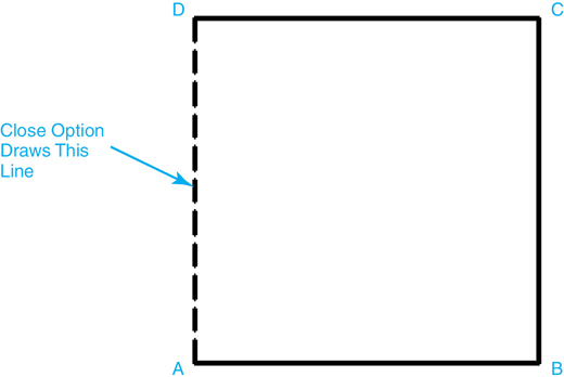
Figure 4-4 Using the Close option
Coordinate Entry Methods
As you’ve seen, to place objects in AutoCAD, you need to specify where in the drawing you want to place them. For example, when drawing a line, AutoCAD prompts you to Specify first point: and to Specify next point:. This process of specifying point locations is called coordinate entry. AutoCAD uses two basic types of coordinate systems: Cartesian coordinates and polar coordinates.
coordinate entry: The process of specifying point locations.
Cartesian Coordinates
In Chapter 1, we discussed the Cartesian coordinate system, where 0,0 is the origin and a point location is described as an x and y coordinate (see Figure 4-5).

Figure 4-5 The Cartesian coordinate system
Using this system, it’s possible to describe accurately any position on a two-dimensional plane. However, while it is possible to use basic Cartesian coordinates all the time, it is not always practical or efficient to do so. For example, let’s look at a 2 × 2 square with its lower-left corner located at the coordinate 3,2. To describe this square using Cartesian coordinates, you would need to calculate the location of each corner by taking the starting coordinate (3,2) and adding the dimensions to the respective x and y coordinates (see Figure 4-6).

Figure 4-6 2 × 2 square coordinates
Exercise 4-3 Drawing with Cartesian Coordinates
![]() Continue from Exercise 4-2.
Continue from Exercise 4-2.
![]() Toggle the Dynamic Input setting off.
Toggle the Dynamic Input setting off.
![]() Start the LINE command. AutoCAD prompts you to:
Start the LINE command. AutoCAD prompts you to:
Specify first point:
![]() Type 3,2<Enter>. AutoCAD places the first point and prompts you to:
Type 3,2<Enter>. AutoCAD places the first point and prompts you to:
Specify next point or [Undo]:
![]() Type 5,2<Enter>. AutoCAD places the second point and prompts you to:
Type 5,2<Enter>. AutoCAD places the second point and prompts you to:
Specify next point or [Undo]:
![]() Type 5,4<Enter>. AutoCAD places the third point and prompts you to:
Type 5,4<Enter>. AutoCAD places the third point and prompts you to:
Specify next point or [Close Undo]:
![]() Type 3,4<Enter>. AutoCAD places the fourth point and prompts you to:
Type 3,4<Enter>. AutoCAD places the fourth point and prompts you to:
Specify next point or [Close Undo]:
![]() Select the Close option to close the square and end the LINE command.
Select the Close option to close the square and end the LINE command.
![]() Save your drawing.
Save your drawing.
Although drawing using only Cartesian coordinates is possible, it’s not an efficient way to draw. The coordinates in the previous exercise are fairly simple, but the problem is made more difficult if the square is rotated or the points do not lie on easily determined coordinates.
To address these issues, AutoCAD gives you some additional ways of specifying coordinates.
Absolute Versus Relative Coordinate Entry
When specifying Cartesian coordinates, you are telling AutoCAD to measure from the absolute origin of the drawing (0,0). For example, if you specified the point 4,2, you are telling AutoCAD to start at the origin and go to the point measured 4 units in the positive X direction and 2 units in the positive Y direction (see Figure 4-5). This is known as absolute coordinate entry.
You can tell AutoCAD to measure coordinates from the last specified point by simply placing the @ character in front of the coordinate—for example, @4,2. By using the @ symbol, you are telling AutoCAD to measure 4 units in the positive X direction and 2 units in the positive Y direction from your current position, or from where you are. This is known as relative coordinate entry.
Let’s redraw the 2 × 2 square, this time using relative coordinate entry.
Exercise 4-4 Drawing with Relative Coordinates
![]() Continue from Exercise 4-3.
Continue from Exercise 4-3.
![]() Toggle the Dynamic Input setting back on.
Toggle the Dynamic Input setting back on.
![]() Start the LINE command. AutoCAD prompts you to:
Start the LINE command. AutoCAD prompts you to:
Specify first point:
![]() Type 6,2<Enter>. AutoCAD places the first point and prompts you to:
Type 6,2<Enter>. AutoCAD places the first point and prompts you to:
Specify next point or [Undo]:
![]() Type @2,0<Enter>. AutoCAD places a point 2 units to the right of the first point and prompts you to:
Type @2,0<Enter>. AutoCAD places a point 2 units to the right of the first point and prompts you to:
Specify next point or [Undo]:
![]() Type @0,2<Enter>. AutoCAD places a point 2 units above the second point and prompts you to:
Type @0,2<Enter>. AutoCAD places a point 2 units above the second point and prompts you to:
Specify next point or [Close Undo]:
![]() Type @-2,0<Enter>. AutoCAD places a point 2 units to the left of the third point and prompts you to:
Type @-2,0<Enter>. AutoCAD places a point 2 units to the left of the third point and prompts you to:
Specify next point or [Close Undo]:
![]() Select the Close option to close the square and end the LINE command. Your drawing should now resemble Figure 4-7.
Select the Close option to close the square and end the LINE command. Your drawing should now resemble Figure 4-7.

Figure 4-7 Drawing with relative coordinates
![]() Save your drawing.
Save your drawing.
You used absolute coordinate entry to place the first point (6,2), but each subsequent point was measured from the last placed point—i.e., from where you were.
Tip
When Dynamic Input is turned on, all coordinates you enter after the first point are automatically relative. AutoCAD enters the @ prefix automatically so you don’t have to. If you want to enter an absolute coordinate, you just prefix the coordinate with the # symbol (e.g., #2,4<Enter>).
Polar Coordinates
Cartesian coordinates work well when drawing objects have mostly right angles or when coordinates lie on a well-defined grid. However, when drawing objects have angles other than 90°, calculating coordinate locations is quite a bit more difficult. Let’s take our 2 × 2 square and rotate it 45° (see Figure 4-8).
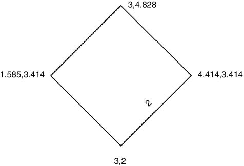
Figure 4-8 The rotated 2 × 2 square
To calculate the location of these coordinates, you’ll need to either use the Pythagorean theorem (x2 + y2 = z2) or use AutoCAD’s polar coordinates.
Polar coordinates use distance and direction to specify locations. For example, if you specify a location of 2<0, 2 is the distance, < is the angle indicator, and 0 is the direction in degrees. The coordinate 2<0 tells AutoCAD to measure 2 units in the 0° direction from the origin (0,0). Remember from Chapter 1 that in AutoCAD angles are measured counterclockwise from 0°, which is east, or to the right, of the origin along the positive X-axis.
Like Cartesian coordinates, polar coordinates can be either absolute (measured from 0,0) or relative (measured from the last specified point). Also, angles can be positive (counterclockwise) or negative (clockwise). Figure 4-9 shows some examples of polar coordinate entry and the resulting point locations.

Figure 4-9 The polar coordinate examples
Now, let’s draw the rotated 2 × 2 square using polar coordinate entry.
Exercise 4-5 Drawing with Polar Coordinates
![]() Continue from Exercise 4-4.
Continue from Exercise 4-4.
![]() Start the LINE command. Type 4,5<Enter> to specify the first point. AutoCAD starts drawing the line and prompts you for the second point.
Start the LINE command. Type 4,5<Enter> to specify the first point. AutoCAD starts drawing the line and prompts you for the second point.
![]() Type @2<45<Enter>. AutoCAD draws a line segment 2 units long at an angle of 45° from the first point.
Type @2<45<Enter>. AutoCAD draws a line segment 2 units long at an angle of 45° from the first point.
![]() Type @2<135<Enter>. AutoCAD draws a line segment 2 units long at an angle of 135° from the second point.
Type @2<135<Enter>. AutoCAD draws a line segment 2 units long at an angle of 135° from the second point.
![]() Type @2<−135<Enter>. AutoCAD draws a line segment 2 units long at an angle of −135° from the third point.
Type @2<−135<Enter>. AutoCAD draws a line segment 2 units long at an angle of −135° from the third point.
![]() Select the Close option to close the square and end the LINE command. Your drawing should now resemble Figure 4-10.
Select the Close option to close the square and end the LINE command. Your drawing should now resemble Figure 4-10.
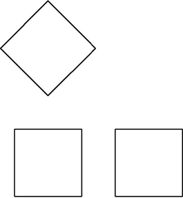
Figure 4-10 Drawing with polar coordinates
![]() Save your drawing.
Save your drawing.
Note
Absolute coordinate entry, whether Cartesian or polar coordinates, is rarely used. The majority of points are specified using either object snaps (see Chapter 5) or some form of relative coordinate entry.
Dynamic Input
As you saw in Chapter 2, AutoCAD’s dynamic prompt moves with your cursor and provides instant feedback as you move around the drawing. One of the advantages of dynamic input is the immediate coordinate and dimensional information it provides while drawing. Using dynamic input, you can use the cursor location to determine the angle and dimensions of the objects as they are being drawn. This is best explained with an example.
Exercise 4-6 Drawing with Dynamic Input
![]() Continue from Exercise 4-5.
Continue from Exercise 4-5.
![]() On the status bar, turn on both the Ortho Mode and Dynamic Input settings.
On the status bar, turn on both the Ortho Mode and Dynamic Input settings.
![]() Start the LINE command, and type 6,5<Enter> to specify the first point.
Start the LINE command, and type 6,5<Enter> to specify the first point.
![]() Drag the cursor to the right. The Ortho Mode setting will lock the cursor movement to the 0° direction.
Drag the cursor to the right. The Ortho Mode setting will lock the cursor movement to the 0° direction.
![]() Type 2<Enter>. AutoCAD draws a line 2 units to the right (angle of 0°).
Type 2<Enter>. AutoCAD draws a line 2 units to the right (angle of 0°).
![]() Drag the cursor up (90°) and type 2<Enter>. AutoCAD draws a line 2 units up (angle of 90°).
Drag the cursor up (90°) and type 2<Enter>. AutoCAD draws a line 2 units up (angle of 90°).
![]() Drag the cursor to the left (180°) and type 2<Enter>. AutoCAD draws a line 2 units to the left (angle of 180°).
Drag the cursor to the left (180°) and type 2<Enter>. AutoCAD draws a line 2 units to the left (angle of 180°).
![]() Press the down arrow and choose Close from the list of options. AutoCAD closes the square and ends the LINE command. Your drawing should now resemble Figure 4-11.
Press the down arrow and choose Close from the list of options. AutoCAD closes the square and ends the LINE command. Your drawing should now resemble Figure 4-11.
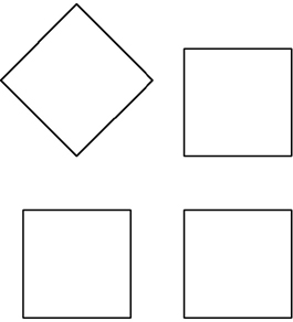
Figure 4-11 Drawing with dynamic input
![]() Save your drawing.
Save your drawing.
Dynamic input automates the process of specifying relative coordinates. When Dynamic Input is turned on, all dimensions and coordinates you type are measured from the last specified point. Dynamic input also allows you to see the length and direction visually without having to calculate the direction angles. You simply point the way and tell AutoCAD how far to go.
We’ve seen that AutoCAD remembers the last specified coordinate. When inputting relative coordinates, AutoCAD will measure coordinates from the last specified point. The LINE command can also make use of the last point. When you start the LINE command, AutoCAD prompts you to specify the first point. If you simply press <Enter>, AutoCAD will start the line from the last specified point.
Drawing Circles
A circle is another basic AutoCAD drawing object. By default, AutoCAD asks for a center coordinate and a radius distance. However, there are a number of other ways to draw a circle. When you start the CIRCLE command, AutoCAD prompts you to Specify center point for circle or ![]() . If you choose the down arrow, you’ll see that you have other options for drawing a circle.
. If you choose the down arrow, you’ll see that you have other options for drawing a circle.
Altogether, there are six different options for creating a circle: Center Radius, Center Diameter, 2 Point, 3 Point, Tangent Tangent Radius, or Tangent Tangent Tangent.
Center Radius
This is AutoCAD’s default method for creating a circle. You can specify the center point using any of the coordinate entry methods. Once you have the center point placed, AutoCAD will then display a rubber-band line and drag a circle from the center point. You can specify the radius either by picking a point on the screen or by typing in a radius value.
Exercise 4-7 Drawing a Circle
![]() Continue from Exercise 4-6.
Continue from Exercise 4-6.
![]() Toggle off the Ortho Mode setting.
Toggle off the Ortho Mode setting.
![]() Start the CIRCLE command. AutoCAD prompts you to Specify center point for circle or
Start the CIRCLE command. AutoCAD prompts you to Specify center point for circle or ![]() .
.
![]() Type 1,3<Enter>. AutoCAD places the center of the circle and starts dragging the radius. A preview image of the circle appears (see Figure 4-12). AutoCAD prompts you to Specify radius of circle or
Type 1,3<Enter>. AutoCAD places the center of the circle and starts dragging the radius. A preview image of the circle appears (see Figure 4-12). AutoCAD prompts you to Specify radius of circle or ![]() .
.
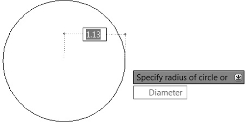
Figure 4-12 The preview image of the circle
![]() Type 1<Enter> to specify a radius of 1. AutoCAD creates the circle and ends the CIRCLE command. Your drawing should now look like Figure 4-13.
Type 1<Enter> to specify a radius of 1. AutoCAD creates the circle and ends the CIRCLE command. Your drawing should now look like Figure 4-13.

Figure 4-13 Drawing a circle
![]() Save your drawing.
Save your drawing.
Circle |
|
|---|---|
Ribbon & Panel: |
Home | Draw |
Menu: |
Draw | Circle |
Command Line: |
CIRCLE |
Command Alias: |
C |
Center Diameter
This is similar to the Center Radius option. Once you specify a center point, AutoCAD prompts you to Specify radius of circle or ![]() .
.
You can then select the Diameter option using your mouse or by typing D<Enter>. AutoCAD will then prompt you for the diameter of the circle. The rubber-band line will now stretch out twice the radius of the circle, and the dynamic input will be located at the center of the circle. You can specify the diameter either by picking a point on the screen or by typing in a diameter.
Exercise 4-8 Drawing a Circle Using Center Diameter
![]() Continue from Exercise 4-7.
Continue from Exercise 4-7.
![]() Start the CIRCLE command. AutoCAD prompts you to Specify center point for circle or
Start the CIRCLE command. AutoCAD prompts you to Specify center point for circle or ![]() .
.
![]() Type 4,3<Enter>. AutoCAD places the center of the circle and starts dragging the radius. AutoCAD prompts you to Specify radius of circle or
Type 4,3<Enter>. AutoCAD places the center of the circle and starts dragging the radius. AutoCAD prompts you to Specify radius of circle or ![]() .
.
![]() Choose Diameter from the options list. AutoCAD prompts you to Specify diameter of circle:. Notice that the default value is the diameter of the last circle drawn (2.00).
Choose Diameter from the options list. AutoCAD prompts you to Specify diameter of circle:. Notice that the default value is the diameter of the last circle drawn (2.00).
![]() Press <Enter> to accept the default diameter value. AutoCAD places the circle and ends the CIRCLE command. Your drawing should resemble Figure 4-14.
Press <Enter> to accept the default diameter value. AutoCAD places the circle and ends the CIRCLE command. Your drawing should resemble Figure 4-14.
Figure 4-14 Drawing a diameter circle
![]() Save your drawing.
Save your drawing.
2 Point Circle
A 2 point circle is defined by specifying two points on the diameter of the circle. To use this option, start the CIRCLE command and either type 2P<Enter> at the prompt or choose 2P from the options list. AutoCAD then asks you to specify the first point of the circle’s diameter and the second point and will draw a circle whose diameter passes through the two points.
Exercise 4-9 Drawing a 2 Point Circle
![]() Continue from Exercise 4-8.
Continue from Exercise 4-8.
![]() Toggle the Ortho Mode setting on.
Toggle the Ortho Mode setting on.
![]() Start the CIRCLE command. AutoCAD prompts you to Specify center point for circle or
Start the CIRCLE command. AutoCAD prompts you to Specify center point for circle or ![]() .
.
![]() Select 2P from the options list. AutoCAD prompts you to Specify first endpoint of circle’s diameter:.
Select 2P from the options list. AutoCAD prompts you to Specify first endpoint of circle’s diameter:.
![]() Type 7,2<Enter> to specify the first point on the circle’s diameter. AutoCAD prompts you to Specify second endpoint of circle’s diameter:.
Type 7,2<Enter> to specify the first point on the circle’s diameter. AutoCAD prompts you to Specify second endpoint of circle’s diameter:.
![]() Drag the cursor up and type 2<Enter> to place the second point on the circle’s diameter. AutoCAD draws the circle and ends the CIRCLE command.
Drag the cursor up and type 2<Enter> to place the second point on the circle’s diameter. AutoCAD draws the circle and ends the CIRCLE command.
![]() Save your drawing. Your drawing should resemble Figure 4-15.
Save your drawing. Your drawing should resemble Figure 4-15.

Figure 4-15 Drawing a 2 point circle
3 Point Circle
A 3 point circle is defined by specifying three points on the circle’s circumference. To use this option, start the CIRCLE command and type 3P<Enter> or choose 3P from the options list. AutoCAD asks you to specify the first point on the circle, then the second point. Once you specify the second point, AutoCAD will prompt you for the third and will drag a circle that passes through the first two points. AutoCAD will not display the preview circle until the first two points are specified.
Exercise 4-10 Drawing a 3 Point Circle
![]() Continue from Exercise 4-9.
Continue from Exercise 4-9.
![]() Start the CIRCLE command. AutoCAD prompts you to Specify center point for circle or
Start the CIRCLE command. AutoCAD prompts you to Specify center point for circle or ![]() .
.
![]() Select 3P from the options list. AutoCAD prompts you to Specify first point on circle:.
Select 3P from the options list. AutoCAD prompts you to Specify first point on circle:.
![]() Type 7,5<Enter> to specify the first point on the circle.
Type 7,5<Enter> to specify the first point on the circle.
![]() Type 1,1<Enter> to specify the second point on the circle. The dynamic input places the point at the middle of the right side of the square. AutoCAD now displays the preview circle. AutoCAD prompts you to Specify third point on circle:.
Type 1,1<Enter> to specify the second point on the circle. The dynamic input places the point at the middle of the right side of the square. AutoCAD now displays the preview circle. AutoCAD prompts you to Specify third point on circle:.
![]() Drag your cursor to the left and type 2<Enter> to place the last point on the circle. AutoCAD creates the circle and ends the CIRCLE command.
Drag your cursor to the left and type 2<Enter> to place the last point on the circle. AutoCAD creates the circle and ends the CIRCLE command.
![]() Save your drawing. Your drawing should resemble Figure 4-16.
Save your drawing. Your drawing should resemble Figure 4-16.

Figure 4-16 Drawing a 3 point circle
Tangent Tangent Radius
A tangent tangent radius, or TTR, circle is defined by two points of tangency on existing objects and a radius value. This method of creating a circle is a bit different from the other methods. First, the points of tangency must be on existing objects. AutoCAD uses the Tangent object snap to get the points of tangency. Second, the exact points of tangency are determined only after you specify the radius. Because of this, you can’t drag and pick the radius of the circle. Last, it is possible to specify a combination of tangent points and a radius that cannot be created. In this case, AutoCAD will simply tell you:
Circle does not exist.
Exercise 4-11 Drawing a TTR Circle
![]() Continue from Exercise 4-10.
Continue from Exercise 4-10.
![]() Start the CIRCLE command. AutoCAD prompts you to Specify center point for circle or
Start the CIRCLE command. AutoCAD prompts you to Specify center point for circle or ![]() .
.
![]() Select Ttr from the options list. AutoCAD prompts you to Specify point on object for first tangent of circle:.
Select Ttr from the options list. AutoCAD prompts you to Specify point on object for first tangent of circle:.
![]() Drag your cursor over the lower-left side of the rotated box (see Figure 4-17). AutoCAD will display the Deferred Tangent object snap.
Drag your cursor over the lower-left side of the rotated box (see Figure 4-17). AutoCAD will display the Deferred Tangent object snap.

Figure 4-17 The Deferred Tangent object snap
![]() Pick anywhere along the line to select the first tangent point. AutoCAD prompts you to Specify point on object for second tangent of circle:.
Pick anywhere along the line to select the first tangent point. AutoCAD prompts you to Specify point on object for second tangent of circle:.
![]() Pick anywhere along the lower-right line to select the second tangent point. AutoCAD prompts you to Specify radius of circle<1.00>:.
Pick anywhere along the lower-right line to select the second tangent point. AutoCAD prompts you to Specify radius of circle<1.00>:.
![]() Press <Enter> to accept the default circle radius (1.00). AutoCAD creates the circle and ends the CIRCLE command.
Press <Enter> to accept the default circle radius (1.00). AutoCAD creates the circle and ends the CIRCLE command.
![]() Save your drawing. Your drawing should resemble Figure 4-18.
Save your drawing. Your drawing should resemble Figure 4-18.

Figure 4-18 Drawing a TTR circle
Tan, Tan, Tan. When choosing the CIRCLE command from the Draw panel, you’ll notice that there is yet another option listed: Tan, Tan, Tan. This is technically not an option of the CIRCLE command. It is simply a method of constructing a circle using the 3P option of the CIRCLE command along with AutoCAD’s Tangent object snap.
Drawing Arcs
Arcs are another type of basic drawing object. An arc is simply a segment of a circle. Like circles, arcs are defined by a center point and radius, but they also include a starting angle and an ending angle (see Figure 4-19). The part of the circle between the start and end angles defines the arc segment. Keep in mind that, by default, AutoCAD measures angles in a counterclockwise direction, with 0 along the positive portion of the X-axis. Likewise, arcs are also drawn in a counterclockwise direction. This means that by default, AutoCAD will draw the arc segment from the starting angle in a counterclockwise direction toward the ending angle.
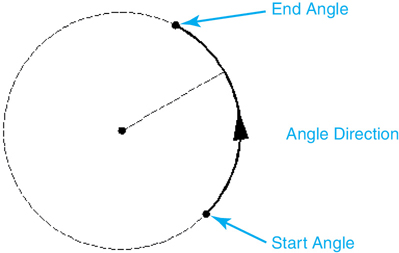
Figure 4-19 How arcs are defined
Tip
It is possible to draw an arc in either direction by holding the <Ctrl> key and switching directions as you draw.
The ARC Command
Arcs are created with the ARC command.
Arc |
|
|---|---|
Ribbon & Panel: |
Home | Draw |
Menu: |
Draw | Arc |
Command Line: |
ARC |
Command Alias: |
A |
3 Point Arc
By default, AutoCAD prompts you to pick three points: a start point, a second point along the arc, and the endpoint of the arc. From these three points, AutoCAD will calculate the center point and radius of the arc as well as the starting and ending angles. AutoCAD draws an arc segment through the three points you specify. Direction is not important when picking points for a 3 point arc. AutoCAD will draw the arc through the three points in the order they are specified (see Figure 4-20).
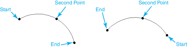
Figure 4-20 3 point arcs
You may find that, while easy to use, the 3 point method of drawing an arc is not always practical. You may not know the exact location of a second point on the arc, or even the start point or endpoint of the arc. You might know the radius of the arc, the center point, the included angle, or some combination of these properties.
Arc Options
AutoCAD provides a number of options for constructing arcs. These options can be used in various combinations, depending on what information you know. The options are described next.
Start |
The Start option defines the start point of the arc. |
End |
The End option defines the endpoint of the arc. |
Center |
The Center option defines the center point of the arc. |
Radius |
The Radius option defines the radius of the arc. This option can be used only after the start point and endpoint of the arc are defined. |
Angle |
The Angle option defines the included angle of the arc. This is the difference between the starting angle and the ending angle. The Angle option is available only after the start point and either the endpoint or the center point have been picked. |
Length |
The Length option defines the length of the chord between the start point and endpoint of the arc (see Figure 4-21). |
Direction |
The Direction option defines the direction of a line tangent to the start point of the arc (see Figure 4-21). The Direction option can be used only after the start point and endpoint of the arc have been defined. |
Continue |
This is not technically an option, but a behavior of the ARC command. When you start the ARC command, if you press <Enter> at the first prompt, AutoCAD will start drawing an arc segment tangent to the previous line or arc segment drawn. AutoCAD uses the last specified point as the start point and determines the tangent direction from the previous line or arc segment. AutoCAD then prompts you for the endpoint of the arc (see Figure 4-21). |
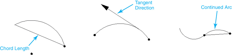
Figure 4-21 Arc options
Using the ARC Command
When you start the ARC command, AutoCAD will prompt you to Specify start point of arc or ![]() . You can specify the start point, choose the Center option, or press <Enter> to create an arc tangent to the previous line or arc segment. Depending on the options you choose, AutoCAD will present you with other options. There are 10 different combinations of options for drawing an arc.
. You can specify the start point, choose the Center option, or press <Enter> to create an arc tangent to the previous line or arc segment. Depending on the options you choose, AutoCAD will present you with other options. There are 10 different combinations of options for drawing an arc.
When accessing the ARC command from the Draw panel, you’ll see the 10 different combinations of options used to draw arcs (see Figure 4-22). When using these menu options, AutoCAD will automatically type the options for you after each point selection.

Figure 4-22 The Home|Draw|Arc menu
Tip
Before drawing an arc, take a moment to consider what information you know about the arc. This will help you decide which ARC command options to use.
Let’s look at some examples of drawing arcs.
Exercise 4-12 Drawing Arcs
![]() Continue from Exercise 4-11.
Continue from Exercise 4-11.
![]() Choose Start, End, Radius from the Draw panel. AutoCAD prompts you to Specify start point of arc or
Choose Start, End, Radius from the Draw panel. AutoCAD prompts you to Specify start point of arc or ![]() .
.
![]() Type 8,7<Enter> to start the arc at the top-right corner of the upper-right box. A rubber-band line stretches from the point. AutoCAD prompts you to Specify end point of arc:. Notice that AutoCAD has specified the End option for you.
Type 8,7<Enter> to start the arc at the top-right corner of the upper-right box. A rubber-band line stretches from the point. AutoCAD prompts you to Specify end point of arc:. Notice that AutoCAD has specified the End option for you.
![]() Type 6,7<Enter> to specify the upper-left corner of the square. A preview image of the arc appears, and a rubber-band line stretches from the end of the arc. AutoCAD has also specified the Radius option for you. AutoCAD prompts you to Specify radius of arc (hold Ctrl to switch direction):.
Type 6,7<Enter> to specify the upper-left corner of the square. A preview image of the arc appears, and a rubber-band line stretches from the end of the arc. AutoCAD has also specified the Radius option for you. AutoCAD prompts you to Specify radius of arc (hold Ctrl to switch direction):.
![]() Type 1<Enter> to specify a radius of 1. AutoCAD draws the arc. Your drawing should look like Figure 4-23.
Type 1<Enter> to specify a radius of 1. AutoCAD draws the arc. Your drawing should look like Figure 4-23.
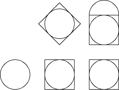
Figure 4-23 Start, End, Radius arc
![]() Choose Start, End, Angle from the Draw panel. AutoCAD prompts you to Specify start point of arc or
Choose Start, End, Angle from the Draw panel. AutoCAD prompts you to Specify start point of arc or ![]() .
.
![]() Type 0,3<Enter> to start the arc at the left quadrant of the circle on the left of your drawing. A rubber-band line stretches from the point. AutoCAD prompts you to Specify end point of arc:.
Type 0,3<Enter> to start the arc at the left quadrant of the circle on the left of your drawing. A rubber-band line stretches from the point. AutoCAD prompts you to Specify end point of arc:.
![]() Type 1,3<Enter> to specify the center of the circle. A preview image of the arc appears, and a rubber-band line stretches from the start of the arc. AutoCAD prompts you to Specify included angle (hold Ctrl to switch direction):.
Type 1,3<Enter> to specify the center of the circle. A preview image of the arc appears, and a rubber-band line stretches from the start of the arc. AutoCAD prompts you to Specify included angle (hold Ctrl to switch direction):.
![]() Drag the cursor up and type 180<Enter>. AutoCAD draws an arc with a 180° included angle from the start point to the endpoint in a counterclockwise direction. Your drawing should look like Figure 4-24.
Drag the cursor up and type 180<Enter>. AutoCAD draws an arc with a 180° included angle from the start point to the endpoint in a counterclockwise direction. Your drawing should look like Figure 4-24.
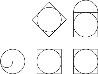
Figure 4-24 Start, End, Angle arc
![]() Press <Enter> to repeat the ARC command. AutoCAD prompts you to Specify start point of arc or
Press <Enter> to repeat the ARC command. AutoCAD prompts you to Specify start point of arc or ![]() .
.
![]() Press <Enter> to continue an arc from the end of the last arc. AutoCAD stretches a tangent arc from the end of the last arc and prompts you to Specify endpoint of arc (hold Ctrl to switch direction):.
Press <Enter> to continue an arc from the end of the last arc. AutoCAD stretches a tangent arc from the end of the last arc and prompts you to Specify endpoint of arc (hold Ctrl to switch direction):.
![]() Drag the cursor to the right and type 1<Enter> to specify the right quadrant of the circle. AutoCAD places the arc tangent to the first arc. Your drawing should look like Figure 4-25.
Drag the cursor to the right and type 1<Enter> to specify the right quadrant of the circle. AutoCAD places the arc tangent to the first arc. Your drawing should look like Figure 4-25.

Figure 4-25 A continued arc
![]() Save your drawing.
Save your drawing.
Drawing Ellipses
An ellipse (or oval) is similar in definition to a circle except that it has both a major and a minor radius (see Figure 4-26).

Figure 4-26 An ellipse
An ellipse is created with the ELLIPSE command.
You can construct an ellipse either by specifying the center point and points on the major and minor radii or by picking points on the major and minor axes.
Let’s draw an ellipse.
Ellipse |
|
|---|---|
Ribbon & Panel: |
Home | Draw |
Menu: |
Draw | Ellipse |
Command Line: |
ELLIPSE |
Command Alias: |
EL |
Exercise 4-13 Drawing an Ellipse
![]() Continue from Exercise 4-12.
Continue from Exercise 4-12.
![]() Toggle the Ortho Mode setting on.
Toggle the Ortho Mode setting on.
![]() Start the ELLIPSE command. AutoCAD prompts you to Specify center of ellipse:.
Start the ELLIPSE command. AutoCAD prompts you to Specify center of ellipse:.
![]() Type 1,6<Enter>. AutoCAD drags a rubber-band line from the point. AutoCAD prompts you to Specify endpoint of axis:.
Type 1,6<Enter>. AutoCAD drags a rubber-band line from the point. AutoCAD prompts you to Specify endpoint of axis:.
![]() Pick a point 1 inch to the right of the first point. A rubber-band line stretches from the center point. AutoCAD prompts you to Specify distance to other axis or
Pick a point 1 inch to the right of the first point. A rubber-band line stretches from the center point. AutoCAD prompts you to Specify distance to other axis or ![]() .
.
![]() Drag the mouse around to see how the shape of the ellipse changes as you move it. Pick a point 0.5 inch above the center point to create the ellipse. Your drawing should look like Figure 4-27.
Drag the mouse around to see how the shape of the ellipse changes as you move it. Pick a point 0.5 inch above the center point to create the ellipse. Your drawing should look like Figure 4-27.

Figure 4-27 An ellipse
![]() Save your drawing.
Save your drawing.
When drawing an ellipse, once you specify the major axis (by picking either a center and major radius or two points on the major axis), you’ll have a Rotation option available. The Rotation option allows you to draw the ellipse as though it is a circle being viewed from an angle. Imagine holding a hula hoop directly in front of you so it looks like a circle. Now imagine tilting the hula hoop away from you. The outline of the tilted circle is now an ellipse. When using the Rotation option, you are specifying that tilt angle. A tilt angle of 0 will draw a circular ellipse (the major and minor axes are equal). You can specify a maximum tilt angle of 89.4°. Figure 4-28 shows the results of different rotation angles.

Figure 4-28 The Rotation option values of the ELLIPSE command
Elliptical Arcs
Unlike circular arcs, elliptical arcs are drawn with the ELLIPSE command. In fact, AutoCAD considers an ellipse and an elliptical arc as the same type of object. An ellipse has an included angle of 360°, whereas an elliptical arc has an included angle of less than 360°.
To create an elliptical arc, start the ELLIPSE command and select the Arc option or choose the Ellipse Arc tool from the Draw panel. Once you have defined the ellipse, you are prompted for the start angle and end angle. Like circular arcs, AutoCAD draws the elliptical arcs from the start angle to the end angle in a counterclockwise direction.
Exercise 4-14 Drawing an Elliptical Arc
![]() Continue from Exercise 4-13.
Continue from Exercise 4-13.
![]() Select the Undo tool and undo the ellipse drawn in Exercise 4-13.
Select the Undo tool and undo the ellipse drawn in Exercise 4-13.
![]() Toggle the Ortho Mode setting on.
Toggle the Ortho Mode setting on.
![]() Choose the Ellipse Arc tool from the Draw panel. AutoCAD prompts you to Specify axis endpoint of ellipse or
Choose the Ellipse Arc tool from the Draw panel. AutoCAD prompts you to Specify axis endpoint of ellipse or ![]() .
.
![]() Type 0,6<Enter>. AutoCAD drags a rubber-band line from the point. AutoCAD prompts you to Specify other endpoint of axis:.
Type 0,6<Enter>. AutoCAD drags a rubber-band line from the point. AutoCAD prompts you to Specify other endpoint of axis:.
![]() Pick a point 2 inches to the right of the first point. AutoCAD will calculate the midpoint of that line and use it for the center of the ellipse. A rubber-band line stretches from this center point. AutoCAD prompts you to Specify distance to other axis or
Pick a point 2 inches to the right of the first point. AutoCAD will calculate the midpoint of that line and use it for the center of the ellipse. A rubber-band line stretches from this center point. AutoCAD prompts you to Specify distance to other axis or ![]() .
.
![]() Pick a point 0.5 inch above the center point to create the ellipse. AutoCAD prompts you to Specify start angle or
Pick a point 0.5 inch above the center point to create the ellipse. AutoCAD prompts you to Specify start angle or ![]() .
.
![]() Pick a point at 0° along the ellipse to specify the start angle. AutoCAD prompts you to Specify end angle or
Pick a point at 0° along the ellipse to specify the start angle. AutoCAD prompts you to Specify end angle or ![]() .
.
![]() Pick a second point at 90° along the ellipse to specify the end angle. The elliptical arc is created between the start and end angles. Your drawing should look like Figure 4-29.
Pick a second point at 90° along the ellipse to specify the end angle. The elliptical arc is created between the start and end angles. Your drawing should look like Figure 4-29.
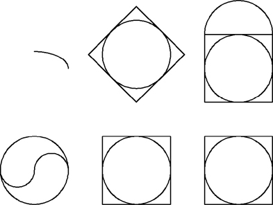
Figure 4-29 The Angle option of the ELLIPSE command
![]() Save your drawing.
Save your drawing.
The Parameter Option. When you are drawing elliptical arcs, the Parameter option is available when you specify the start and end angles of the elliptical arc. The Parameter option uses the same input as the start angle but creates the elliptical arc using the parametric vector equation
p(u) = c+ a* cos(u) + b* sin(u)
where c is the center of the ellipse, and a and b are its major and minor axes, respectively.
Points
Another basic drawing object is the point. To draw a point, AutoCAD simply prompts you to specify a point.
point: A one-dimensional object that is defined as a single coordinate in space. Points have no length or width, only a coordinate location.
Point |
|
|---|---|
Ribbon & Panel: |
None |
Menu: |
Draw | Point |
Command Line: |
POINT |
Command Alias: |
PO |
Exercise 4-15 Drawing a Point
![]() Continue from Exercise 4-14.
Continue from Exercise 4-14.
![]() Start the POINT command. AutoCAD prompts you to Specify a point:.
Start the POINT command. AutoCAD prompts you to Specify a point:.
![]() Pick a point on the screen. AutoCAD will place a point object.
Pick a point on the screen. AutoCAD will place a point object.
![]() Press <Enter> or <Esc> to end the command.
Press <Enter> or <Esc> to end the command.
Points can be difficult to see. By default, points appear as dots with no real size or shape. When you zoom in on a point, it does not get larger. If you place a point directly on top of another object, you might not see it at all. However, you can change the appearance of points to make them easier to spot.
Point Styles
When you start the POINT command, AutoCAD shows you the current value of the PDMODE and PDSIZE system variables in the command line.
Current point modes: PDMODE=0.0000
PDSIZE=0.0000
Point Style |
|
|---|---|
Ribbon & Panel: |
Home | Utilities |
Menu: |
Format | Point Style... |
Command Line: |
DDPTYPE |
Command Alias: |
None |
Note
Keep in mind that the point style and the point size are global settings, meaning that all the points in the drawing are affected by these settings. You cannot have one point displayed using one point style and another point with a different style.
These variables control the look (style) and size of points in your drawing. The DDPTYPE command allows you to set the PDMODE and PDSIZE system variables.
Note
You can choose a point style that will make all points invisible (PDMODE = 1). When this point style is selected, points in your drawing will not be displayed on your screen but can still be moved, copied, erased, etc.
When you start the DDPTYPE command, the Point Style dialog box appears (see Figure 4-30).
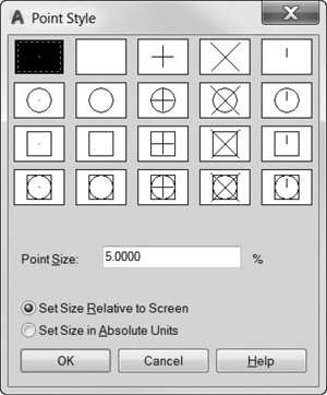
Figure 4-30 The Point Style dialog box
You can choose the desired point style as well as specify a display size for the points. Point size can be entered as an absolute size (for example, 0.1″) or as a relative size (a percentage of the display height). When using a relative point size, AutoCAD will recalculate the point size every time the drawing regenerates.
Exercise 4-16 Changing the Point Style
![]() Continue from Exercise 4-15.
Continue from Exercise 4-15.
![]() Type DDPTYPE <Enter>. The Point Style dialog box is displayed.
Type DDPTYPE <Enter>. The Point Style dialog box is displayed.
![]() Choose the point style shown in Figure 4-31 and choose OK to close the dialog box.
Choose the point style shown in Figure 4-31 and choose OK to close the dialog box.

Figure 4-31 Choosing a point style
![]() Type REGEN<Enter> to regenerate your drawing. AutoCAD updates the point display.
Type REGEN<Enter> to regenerate your drawing. AutoCAD updates the point display.
![]() Save your drawing.
Save your drawing.
The values for PDMODE and their associated shapes are shown in Figure 4-32.
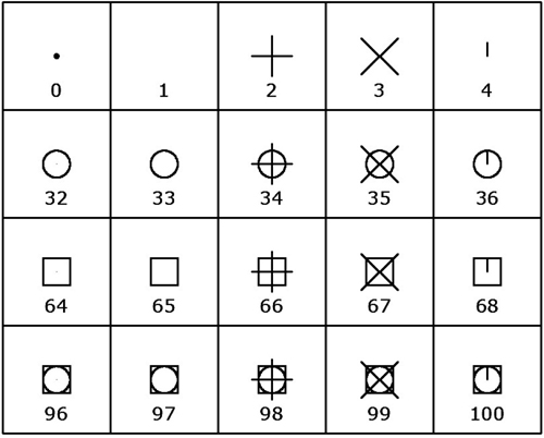
Figure 4-32 PDMODE values and their associated point styles
When you use the POINT command, the values shown for PDSIZE will be either positive numbers or negative numbers. Positive numbers indicate an absolute size, and negative numbers indicate a percentage of the viewport height. For example, a PDSIZE value of -10.0 would make points 10% of the current display area. A value of (+)10 would create points that were 10 units tall. A PDSIZE value of 0.0 will default the point size to 5% of the current display height. The PDSIZE variable has no effect when PDMODE is set to 0 (a dot) or 1 (blank).
Points can be used for a number of things, including simple markers, and AutoCAD uses them when dimensioning. Points are also used as measurement indicators in the MEASURE and DIVIDE commands.
Measure |
|
|---|---|
Ribbon & Panel: |
Home | Draw |
Menu: |
Draw | Point | Measure |
Command Line: |
MEASURE |
Command Alias: |
ME |
Measure and Divide
The MEASURE and DIVIDE commands are used to automatically place point objects at regular intervals along an existing object. The MEASURE command places points at a specified distance along an object, whereas the DIVIDE command places points so that the object is divided into a specified number of segments.
Divide |
|
|---|---|
Ribbon & Panel: |
Home | Draw |
Menu: |
Draw | Point | Divide |
Command Line: |
DIVIDE |
Command Alias: |
DIV |
Note
Although the command names imply otherwise, the MEASURE and DIVIDE commands are simply methods of placing point objects. The DISTANCE command allows you to measure distances, and the BREAK command (Chapter 8) allows you to break an object into multiple pieces.
Measure. The MEASURE command will prompt you to select an object and then ask you to specify a length. AutoCAD will then place points along the object at the specified interval, starting at the end closest to where you selected the object. For example, in Figure 4-33, if you selected the arc near point 1, AutoCAD would measure the distances from endpoint 1. If you selected the arc near point 2, AutoCAD would measure the distances starting at endpoint 2.
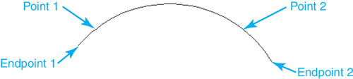
Figure 4-33 Selecting the object to be measured
Points are not placed on the endpoints of objects, and points are placed until the remaining distance is less than the specified distance.
Exercise 4-17 Measuring with Points
![]() Continue from Exercise 4-16.
Continue from Exercise 4-16.
![]() Type DDPTYPE<Enter>. Select the point style that corresponds to PDMODE 3 (see Figure 4-32) and choose OK.
Type DDPTYPE<Enter>. Select the point style that corresponds to PDMODE 3 (see Figure 4-32) and choose OK.
![]() Start the MEASURE command. AutoCAD prompts you to Select object to measure:.
Start the MEASURE command. AutoCAD prompts you to Select object to measure:.
![]() Select the arc on the top right of the drawing, as shown in Figure 4-34. AutoCAD prompts you to Specify length of segment or
Select the arc on the top right of the drawing, as shown in Figure 4-34. AutoCAD prompts you to Specify length of segment or ![]() .
.
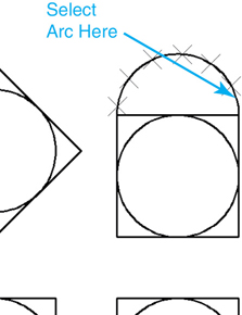
Figure 4-34 Placing points with MEASURE
![]() Type .5<Enter>. AutoCAD places points every .5 unit along the arc starting at the end closest to where you picked. Your drawing should look similar to Figure 4-34.
Type .5<Enter>. AutoCAD places points every .5 unit along the arc starting at the end closest to where you picked. Your drawing should look similar to Figure 4-34.
![]() Save your drawing.
Save your drawing.
Divide. The DIVIDE command prompts you to select an object and then asks for the number of segments. The number must be an integer between 2 and 32767; decimals or fractions are not allowed. AutoCAD will then place points along the object at equal intervals that divide the object into the specified number of segments.
Exercise 4-18 Dividing Objects with Points
![]() Continue from Exercise 4-17.
Continue from Exercise 4-17.
![]() Start the DIVIDE command. AutoCAD prompts you to Select object to divide:.
Start the DIVIDE command. AutoCAD prompts you to Select object to divide:.
![]() Pick anywhere along the line object on the top right of the drawing, as shown in Figure 4-35. AutoCAD prompts you to Enter the number of segments or
Pick anywhere along the line object on the top right of the drawing, as shown in Figure 4-35. AutoCAD prompts you to Enter the number of segments or ![]() .
.
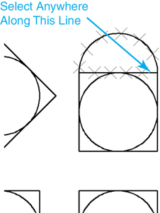
Figure 4-35 Placing points with DIVIDE
![]() Type 5<Enter>. AutoCAD places 4 points along the line that divide the line into 5 equal pieces. The line object has not been changed or broken. Points have just been placed on top of the line. Your drawing should now look like Figure 4-35.
Type 5<Enter>. AutoCAD places 4 points along the line that divide the line into 5 equal pieces. The line object has not been changed or broken. Points have just been placed on top of the line. Your drawing should now look like Figure 4-35.
![]() Save your drawing.
Save your drawing.
Like the MEASURE command, the DIVIDE command does not place points at the endpoints of objects. It will always place one point less than the number of segments you specify (for example, specifying 5 segments creates 4 points, 10 segments creates 9 points, etc.).
Both the MEASURE and DIVIDE commands have a Block option. This option allows you to substitute a block reference for the point objects.
Chapter Summary
The quickest and easiest way to start a new drawing is to base it on a predefined AutoCAD drawing template, or .DWT, file. When you start the NEW command, AutoCAD automatically opens the default Template folder and displays a list of predefined DWT template drawings that come with AutoCAD. Some even have predefined borders and title blocks. You can use these drawings as a starting point for your new drawings, or you can create your own using the SAVEAS command. Either way, it is a great time-saving feature.
AutoCAD comes with five different linear and angular unit settings that can be changed using the UNITS command. If you are using the default acad.dwt template, drawing units are set to decimal inches. Setting linear units to either Architectural or Engineering allows you to input feet by using the apostrophe (’) after a number and inches by using the quote symbol (”). Using the LIMITS command, you can define a drawing area in model space that can be used to define the grid area and area displayed when the ZOOM command is used with the All option.
Point coordinates can be entered using a variety of different methods in AutoCAD. The most basic is absolute coordinate entry where you specify an x and a y position. Relative coordinates allow you to place points “relative” to the last point using the @ prefix, whereas polar coordinates allow you to specify a distance and angle using the < symbol to separate the two. Dynamic input allows you to automatically combine all of the methods visually at the current cursor location.
Finally, learning how to master drawing basic objects such as lines, circles, and arcs lays the groundwork for creating the more complex objects and techniques discussed later in the text. Elliptical objects can be used to represent circles shown at a specific angle of rotation or by indicating a major and a minor axis. Point styles allow you to represent points so that they are useful for dividing objects into a specific number of equal segments or measuring the specified distance along an object.
Chapter Test Questions
Multiple Choice
Circle the correct answer.
1. The @ symbol is used to denote:
a. Relative coordinate entry
b. Polar coordinate systems
c. Cartesian coordinate systems
d. Absolute coordinate entry
2. Drawing templates have the file extension:
a. .DWF
b. .DWT
c. .DXF
d. .DWG
3. Which drawing units are specifically based on imperial (feet-inches) units?
a. Decimal and engineering
b. Engineering and architectural
c. Architectural and fractional
d. Fractional and scientific
4. Which of the following is an example of polar coordinate entry?
a. 3,0
b. 3>90
c. 3<90
d. 90<3
5. Which of the following is an example of relative coordinate entry?
a. 3<4
b. 3<90
c. 3d90
d. @3,4
6. By default, in which direction are positive angles measured in AutoCAD?
a. 90°
b. Clockwise
c. Counterclockwise
d. Depends on where you pick
7. Which of the following is not a valid method of drawing a circle?
a. Center Radius
b. 2 points on the diameter
c. Tangent tangent radius
d. Center circumference
8. Which of the following is not a valid method for constructing an arc?
a. Start, End, Length
b. Start, End, Radius
c. Start, Center, Length
d. 3 Point
9. Drawing templates:
a. Cannot be created in AutoCAD
b. Cannot contain geometry; only drawing settings are stored
c. Can contain both geometry and drawing settings
d. Can be stored only in a specific folder on your computer
10. Points:
a. Do not plot
b. Cannot be erased or modified
c. Cannot change their appearance
d. Are stored as a single coordinate in space
Matching
Write the number of the correct answer on the line.
a. Drawing template ______ |
1. A system of locating points using the X- and Y-axes |
b. Cartesian coordinate system ______ |
2. N32d8′26″E |
c. Scientific unit display ______ |
3. Command used to place points at a specified interval along an object |
d. DIVIDE ______ |
4. The active drawing area. In layout space, it determines the size of your paper |
e. Circle ______ |
5. A drawing object defined by a center point and a radius length |
f. MEASURE ______ |
6. A drawing file used as a starting point when creating new drawings |
g. Point objects ______ |
7. 1.4200E101 |
h. Architectural units ______ |
8. Command used to place points at equal distances along an object |
i. Drawing limits ______ |
9. 4′-8 3/16″ |
j. Surveyor’s units ______ |
10. A system of locating points using distance and direction |
True or False
Circle the correct answer.
1. True or False: The UNITS command controls how precisely coordinates are stored in the drawing.
2. True or False: The Length option in the ARC command determines the actual arc length.
3. True or False: An ellipse must have different major and minor axis lengths.
4. True or False: Architectural units are based on imperial (feet-inch) units.
5. True or False: A circle can be drawn tangent to three objects.
6. True or False: Point objects do not plot.
7. True or False: The MEASURE command is used to measure the distance between two points.
8. True or False: The DIVIDE command will break an object into pieces of equal length.
9. True or False: Drawings can use only imperial or metric units.
10. True or False: Point styles can be set separately for each point.
Chapter Projects
 Project 4-1: Lines, Circle, and Arcs [BASIC]
Start a new drawing using the acad.dwt template.
Draw the lines, circles, and arcs shown in Figure 4-36. Do not draw dimensions. Hint: Use the Tan, Tan, Tan circle option to place the corner circles.
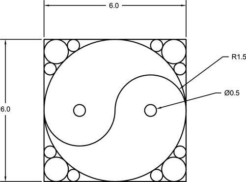
Figure 4-36
Save the drawing as P4-1.
 Project 4-2: B-Size Mechanical Border [INTERMEDIATE]
Start a new drawing using the acad.dwt template.
Set the limits for a 17″ × 11″ drawing area.
Draw the border as shown in Figure 4-37. Do not draw dimensions.

Figure 4-37
Zoom to the drawing extents.
Save the drawing to a template file as Mechanical B-Size.DWT.
 Project 4-3: Architectural D-Size Border (36 × 24) [ADVANCED]
Start a new drawing using the acad.dwt template.
Set linear units to Architectural with precision set to 1/16 ″.
Set angular units to Deg/Min/Sec with precision set to 0d00′900 ″.
Set limits to 36 ″ × 24 ″ for a D-size drawing.
Draw the border as shown in Figure 4-38. Do not draw dimensions.

Figure 4-38
Zoom to the drawing extents.
Save the drawing to a template file as Architectural D-Size.DWT.
 Project 4-4: Electrical Schematic [BASIC]
Start a new drawing using the acad.dwt template.
Draw the electrical symbols shown in Figure 4-39 at the sizes shown using the LINE, CIRCLE, and ARC commands. Hint: Each grid square is equal to 1/8″.
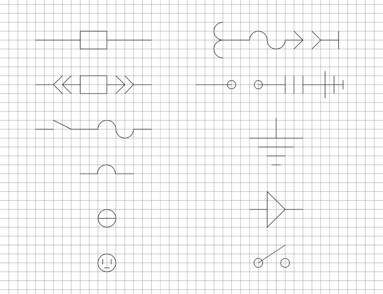
Figure 4-39
Save the drawing as P4-4.
Project 4-5: Residential Architectural Plan [ADVANCED]
Start a new drawing using the acad.dwt template.
Set linear units to Architectural with Precision set to 1/16″.
Set the drawing limits so that the lower-left limit is at 0,0 and the upper-right limit is at 80′-0″, 60′-0″.
Select the Zoom All tool to zoom out to the new larger drawing area.
Draw the building outline as shown in Figure 4-40. Place the corner of the building at 0,0 as shown. Do not include dimensions. Hint: Draw the outline in a counterclockwise direction.

Figure 4-40
Save the drawing as P4-5.