Chapter Eight: Advanced Editing Techniques
Chapter Objectives
Offset objects through a specified distance
Create rectangular, path, and polar arrays
Trim and extend objects
Use the FILLET and CHAMFER commands to modify intersecting objects
Break single objects into multiple objects
Join separate objects into a single object
Use the LENGTHEN command to modify the length of an object
Introduction
As you’ve seen, there is usually more than one way to accomplish a given task in AutoCAD. For example, to create multiple line segments, you could simply draw multiple lines using the LINE command, or you could create a single line segment and copy it using grips or the COPY command. There are multiple ways to create arcs and circles as well as different methods for creating layers and changing object properties.
In Chapter 7, you used basic editing commands such as MOVE, COPY, and ROTATE to modify objects. In this chapter, you’ll examine some editing tools that provide additional functionality. These advanced editing tools are also located on the Modify panel, although a few of them can be accessed only on the expanded Modify panel, as shown in Figure 8-1.
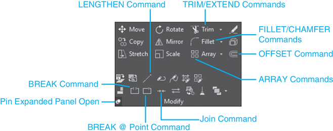
Figure 8-1 The expanded Modify panel
Tip
You can keep the expanded panel displayed while you’re editing by selecting the push-pin icon on the lower left of the expanded panel. Click on the pin again to close the panel later.
Offsetting Objects
To offset an object is to make a copy of an object parallel to the original. This is similar to the COPY command but allows you to make parallel copies at a specified distance from the original. This can be used to make concentric arcs and circles as well as parallel lines (such as roads, walls, etc.). Offsetting is done with the OFFSET command.
offset: To create a parallel copy of an object.
The OFFSET command works by copying an object a specified distance away from the original or source object. When using the OFFSET command, you specify a distance, select an object to offset, and tell AutoCAD on which side of the original object you want to place the new object. To provide the offset distance, you can either specify the distance or pick a point that the new object will pass through. The OFFSET command has three options: Through, Erase, and Layer.
OFFSET |
|
|---|---|
Ribbon & Panel: |
Home | Modify |
Menu: |
Modify | Offset |
Command Line: |
OFFSET |
Command Alias: |
0 |
Through |
Allows you to pick a point that the new object will pass through. AutoCAD measures the distance from the point to the source object |
Erase |
Controls whether the source object is kept or deleted after the offset is complete. You can answer Yes (erase the source object) or No (keep the source object). |
Layer |
Allows you to control the layer of the new object. You can choose to have the new object take on the current layer setting or retain the layer setting of the source object. |
Offsetting an Object a Specified Distance
Specifying a distance is the default method and the most commonly used. When specifying a distance, you can simply type in the distance or pick two points. If you pick two points, AutoCAD will measure the distance between the two points and use that as the offset distance.
Tip
Whenever AutoCAD asks you to provide a numeric value, such as a length or distance, you can usually pick two points and have AutoCAD measure the distance.
Offsetting Through a Point
It is also possible to offset objects through a point that you pick in the drawing using the Through option. Typically, this is done in conjunction with object snaps so that you can snap to specific key features in your drawing. The easiest way to specify the Through option is to press <Enter> when AutoCAD prompts you to Select object to offset or ![]() .
.
Offset Options
By default, the OFFSET command will copy the selected object on the same layer as the original, or source, object. The Layer option allows you to offset an object on the current layer. The Erase option allows you to erase the original object. The current settings are displayed at the command line each time you select the OFFSET command.
Tip
The OFFSET command continues to prompt you to Select object to offset or ![]() until you press <Enter> so that it is possible to offset multiple objects without exiting the command. Even better, after you select an object to offset, the Multiple option is available so that you can make multiple copies the same distance apart by continuing to click with your mouse.
until you press <Enter> so that it is possible to offset multiple objects without exiting the command. Even better, after you select an object to offset, the Multiple option is available so that you can make multiple copies the same distance apart by continuing to click with your mouse.
Exercise 8-1 Offsetting Objects
![]() Start a new drawing using the acad.dwt drawing template.
Start a new drawing using the acad.dwt drawing template.
![]() Create two layers with the following settings:
Create two layers with the following settings:
C-ROAD, Continuous, Color 7 (White)
C-ROAD-CNTR, Center, Color 5 (Blue)
Set layer C-ROAD-CNTR as the current layer.
![]() Set the LTSCALE system variable to 12.
Set the LTSCALE system variable to 12.
![]() Draw a line from the coordinates 100,100 to 100,250. Zoom out using the Zoom Extents tool so the line is centered in the screen.
Draw a line from the coordinates 100,100 to 100,250. Zoom out using the Zoom Extents tool so the line is centered in the screen.
![]() Set the C-ROAD layer current and draw a circle centered at 100,250 with a radius of 35.
Set the C-ROAD layer current and draw a circle centered at 100,250 with a radius of 35.
![]() Start the OFFSET command. AutoCAD prompts you to Specify offset distance or
Start the OFFSET command. AutoCAD prompts you to Specify offset distance or ![]() .
.
![]() Press <Enter> to select the Through option. AutoCAD prompts you to Select object to offset or
Press <Enter> to select the Through option. AutoCAD prompts you to Select object to offset or ![]() .
.
![]() Select the centerline. AutoCAD prompts you to Specify point on side to offset or
Select the centerline. AutoCAD prompts you to Specify point on side to offset or ![]() .
.
![]() Type QUA<Enter> to activate the Quadrant object snap.
Type QUA<Enter> to activate the Quadrant object snap.
![]() Move your cursor to the right side quadrant point on the circle, and pick a point when the Quadrant object snap AutoSnap marker is displayed. The centerline is offset through the circle quadrant point on the same layer and linetype as the original centerline.
Move your cursor to the right side quadrant point on the circle, and pick a point when the Quadrant object snap AutoSnap marker is displayed. The centerline is offset through the circle quadrant point on the same layer and linetype as the original centerline.
![]() Type U<Enter> to undo the offset line, and press <Enter> to exit the OFFSET command.
Type U<Enter> to undo the offset line, and press <Enter> to exit the OFFSET command.
![]() Press <Enter> to run the OFFSET command again. AutoCAD prompts you to Select object to offset or
Press <Enter> to run the OFFSET command again. AutoCAD prompts you to Select object to offset or ![]() .
.
![]() Choose the Layer option, and choose Current. The new objects will be placed on the current drawing layer. AutoCAD again prompts you to Specify offset distance or
Choose the Layer option, and choose Current. The new objects will be placed on the current drawing layer. AutoCAD again prompts you to Specify offset distance or ![]() .
.
![]() Type 25<Enter> to set the offset distance. AutoCAD prompts you to Select object to offset or
Type 25<Enter> to set the offset distance. AutoCAD prompts you to Select object to offset or ![]() .
.
![]() Select the centerline. AutoCAD prompts you to Specify point on side to offset or
Select the centerline. AutoCAD prompts you to Specify point on side to offset or ![]() . Pick anywhere off to the left of the centerline. AutoCAD will create a new line 25 units to the left of the centerline. AutoCAD again prompts you to Select object to offset or
. Pick anywhere off to the left of the centerline. AutoCAD will create a new line 25 units to the left of the centerline. AutoCAD again prompts you to Select object to offset or ![]() .
.
![]() Select the centerline again, and pick anywhere off to the right of the centerline. AutoCAD places a new line 25 units to the right of the original. Both of the new lines are on the current layer (C-ROAD).
Select the centerline again, and pick anywhere off to the right of the centerline. AutoCAD places a new line 25 units to the right of the original. Both of the new lines are on the current layer (C-ROAD).
![]() Press <Enter> or <Esc> to exit the OFFSET command.
Press <Enter> or <Esc> to exit the OFFSET command.
![]() Save your drawing as CH08_EXERCISE1. Your drawing should resemble Figure 8-2.
Save your drawing as CH08_EXERCISE1. Your drawing should resemble Figure 8-2.

Figure 8-2 Offsetting objects
Arraying Objects
An array consists of multiple objects copied in a regular pattern. There are three types of arrays in AutoCAD (see Figure 8-3):
Rectangular Pattern of evenly distributed objects arranged in rows and columns
Path Linear pattern of evenly distributed objects that follow a predefined path
Polar Circular pattern of evenly distributed objects arranged around a center point
array: A rectangular, circular, or linear pattern of objects.
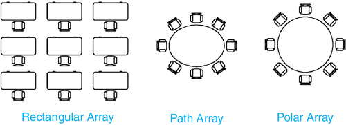
Figure 8-3 Three different array types
Note
It is possible to specify 3D levels when creating an array so that you can copy objects in the Z-axis. Please consult AutoCAD Help for more information regarding any of the 3D features of the different array tools.
The AutoCAD array tools are located on the Array flyout menu on the Modify panel on the Home tab of the ribbon as shown in Figure 8-4.

Figure 8-4 The Array flyout menu
By default, arrayed objects are associated like AutoCAD blocks and dimensions so that they act as one complex unit and individual objects maintain a set relationship to each other. If one object in an array is selected, all of the objects in the array are highlighted. The Array context tab of the ribbon shown in Figure 8-5 is swapped in place of the current tab of the ribbon at the top of the AutoCAD drawing window, so it is easy to edit the array without starting over.
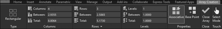
Figure 8-5 The Array context tab of the ribbon
The Array context tab of the ribbon allows you to change any of the array properties, update or replace individual array objects, and even reset an array back to its original settings while maintaining the array’s associativity. The Edit Source tool allows you to update a single array object individually using regular AutoCAD commands and then elect to either save or discard changes via an Edit Array panel that gets appended to the right end of the current tab of the ribbon.
Tip
It is also possible to edit array objects individually by holding down the <Ctrl> key while selecting the object(s) first. You can then use most of the regular modify commands as you would normally.
In addition to the Array context tab of the ribbon, many array options and settings are provided via right-click shortcut menus and multifunctional grips that are displayed when an array is selected in the drawing, as shown in Figure 8-6.

Figure 8-6 Multifunctional Array grips
Note
It is possible to include parametric geometry and expressions when creating an array so that even more complex relationships between array objects can be established. Both of these topics are beyond the scope of this text, so please consult AutoCAD Help for additional information.
Creating a Rectangular Array
The Rectangular Array tool allows you to copy objects equidistantly to create any combination of rows and columns (see Figure 8-7).
After you choose the Rectangular Array tool, select the object(s) you want to array, and press <Enter>. AutoCAD automatically creates a default array with 3 rows and 4 columns. AutoCAD also replaces the standard ribbon with the Array Creation context tab of the ribbon and turns on multifunctional grips. To specify different array options other than the defaults, you can either use the Array Creation context tab of the ribbon, pick a grip to edit in grip mode, or select one of the following command options:
RECTANGULAR ARRAY |
|
|---|---|
Ribbon & Panel: |
Home | Modify |
Menu: |
Modify Array | Rectangular Array |
Command Line: |
ARRAYRECT |
Command Alias: |
None |

Figure 8-7 Rectangular array of objects
Associative Specify whether to create an array of associated objects, or individual objects
Base Point Specify a new base point
COUnt Specify the number of rows and columns
Spacing Change spacing between rows and columns
COLumns Change the number and spacing of columns
Rows Change the number and spacing of rows
Levels 3D setting that allows you to change the number of levels in the Z-axis
eXit Accept all settings and end the command
Tip
If you want to create an old-style array that has no associativity between array objects, set the Associative option to No when creating the array.
Exercise 8-2 Creating a Rectangular Array
![]() Start a new drawing using the acad.dwt drawing template.
Start a new drawing using the acad.dwt drawing template.
![]() Draw the geometry shown in Figure 8-8.
Draw the geometry shown in Figure 8-8.

Figure 8-8 A rectangle and circle
![]() Select the Rectangular Array tool from the Modify panel on the Home tab of the ribbon.
Select the Rectangular Array tool from the Modify panel on the Home tab of the ribbon.
![]() Select the circle, and press <Enter>.
Select the circle, and press <Enter>.
![]() Select the COUnt option.
Select the COUnt option.
![]() Specify 3 columns and 3 rows.
Specify 3 columns and 3 rows.
![]() Select the Spacing option.
Select the Spacing option.
![]() Type 5.25<Enter> to specify the distance between columns.
Type 5.25<Enter> to specify the distance between columns.
![]() Type 3.25<Enter> to specify the distance between rows.
Type 3.25<Enter> to specify the distance between rows.
![]() Press <Enter> again to exit the Rectangular Array tool.
Press <Enter> again to exit the Rectangular Array tool.
![]() Hold down the <Ctrl> key, and select the circle at the center of the part.
Hold down the <Ctrl> key, and select the circle at the center of the part.
![]() Select the Erase tool, or press the <Del> key and erase the circle.
Select the Erase tool, or press the <Del> key and erase the circle.
![]() Save your drawing as CH08_EXERCISE2. Your drawing should look like Figure 8-9.
Save your drawing as CH08_EXERCISE2. Your drawing should look like Figure 8-9.
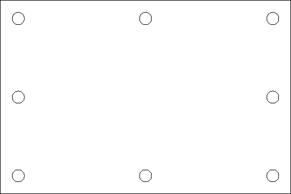
Figure 8-9 A rectangular array
Creating a Path Array
The Path Array tool allows you to copy objects evenly along a path that can be defined using a line, polyline, spline, arc, circle, or ellipse. You have the option of either specifying the distance between each object or letting AutoCAD figure it out based on the total distance and number of copies, as shown in Figure 8-10.
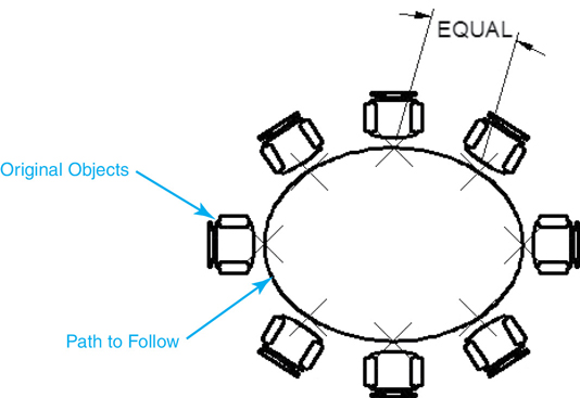
Figure 8-10 Path array of objects
PATH ARRAY |
|
|---|---|
Ribbon & Panel: |
Home | Modify |
Menu: |
Modify | Array | Path Array |
Command Line: |
ARRAYPATH |
Command Alias: |
None |
By default, path array objects are associative so that they will automatically update if the associated path curve changes. For instance, if you choose to divide the path into equal segments, the spacing between the objects automatically adjusts if the length of the path changes.
After you choose the Path Array tool and select the object(s) you want to array, you define the path you want the selected object(s) to follow by selecting one of the valid object types listed above. Once the path is defined and you press <Enter>, AutoCAD automatically creates a default array. AutoCAD also replaces the standard ribbon with the Array Creation context tab of the ribbon and turns on multifunctional grips. To specify different array options other than the defaults, you can either use the Array Creation context tab of the ribbon, pick a grip to edit in grip mode, or select one of the following command options:
Associative Specify whether to create an array of associated objects or individual objects
Method Specify whether to divide the path into equal segments or measure the distance between arrayed objects
Base Point Specify a new base point
Tangent direction Specify how the arrayed items are aligned relative to the starting direction
Items Change the total number of items
Rows Change the number and spacing of rows
Levels 3D setting that allows you to change the number of levels in the Z-axis
Align Items Specify whether to align each item with the path direction
Z Direction 3D setting that controls whether items follow their original Z direction
eXit Accept all settings and end the command
Exercise 8-3 Creating a Path Array
![]() Start a new drawing using the acad.dwt drawing template.
Start a new drawing using the acad.dwt drawing template.
![]() Draw the circle and ellipse shown in Figure 8-11.
Draw the circle and ellipse shown in Figure 8-11.

Figure 8-11 A circle and an ellipse
![]() Select the Path Array tool from the Modify panel on the Home tab of the ribbon.
Select the Path Array tool from the Modify panel on the Home tab of the ribbon.
![]() Select the circle and press <Enter>.
Select the circle and press <Enter>.
![]() Select the ellipse when prompted to select a path curve.
Select the ellipse when prompted to select a path curve.
![]() Select the Method option.
Select the Method option.
![]() Select the Divide option.
Select the Divide option.
![]() Select the Items option.
Select the Items option.
![]() Type 8<Enter> to specify the number of items (copies).
Type 8<Enter> to specify the number of items (copies).
![]() Press <Enter> again to exit the Path Array command. Your drawing should look like Figure 8-12.
Press <Enter> again to exit the Path Array command. Your drawing should look like Figure 8-12.
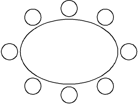
Figure 8-12 A path array
![]() Select the ellipse so grips are displayed.
Select the ellipse so grips are displayed.
![]() Select one of the perimeter grips on the ellipse, and resize it by stretching the point in or out. Notice how the array objects are automatically updated based on the size of the ellipse.
Select one of the perimeter grips on the ellipse, and resize it by stretching the point in or out. Notice how the array objects are automatically updated based on the size of the ellipse.
![]() Save your drawing as CH08_EXERCISE3.
Save your drawing as CH08_EXERCISE3.
Creating a Polar Array
The Polar Array tool allows you to create a circular pattern of objects arranged around a center point by specifying either the number of copies to make and the angle to fill (0°–360°) or the included angle between each object as shown in Figure 8-13.
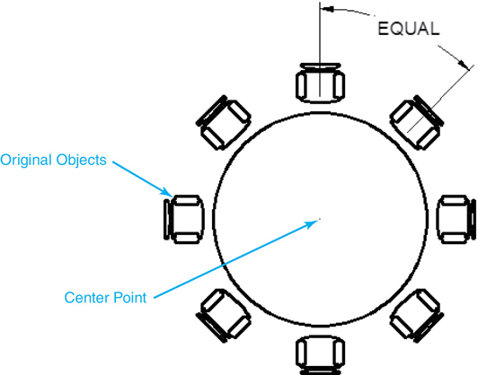
Figure 8-13 Polar array of objects
POLAR ARRAY |
|
|---|---|
Ribbon & Panel: |
Home | Modify |
Menu: |
Modify | Array | Polar Array |
Command Line: |
ARRAYPOLAR |
Command Alias: |
None |
First you choose the Polar Array tool and select the object(s) you want to array. Then you define the center point about which to rotate the objects while they are copied by either picking a point in your drawing or inputting a coordinate value via the keyboard.
Note
By default, objects are aligned using a base point located at the middle, or centroid, of the selected objects as they are copied. The Base point option allows you to change the default by selecting a point in another location. The Axis of rotation option is a 3D fea-ture that can be ignored while working in 2D.
If you enter the total number of copies, AutoCAD will calculate the included angle between objects based on the current angle to fill. If you select the Angle between option, AutoCAD will calculate the angle to fill based on the included angle and the total number of items specified.
Once the center point is defined and you press <Enter>, AutoCAD automatically creates a default array. AutoCAD also replaces the standard ribbon with the Array Creation context tab of the ribbon and turns on multifunctional grips. To specify different array options other than the defaults, you can either use the Array Creation context tab of the ribbon, pick a grip to edit in grip mode, or select one of the following command options:
Associative Specify whether to create an array of associated objects or individual objects
Base Point Specify a new base point
Items Change the total number of items
Angle Between Change the angle between items
Fill Angle Change the angle between the first and the last item in the array
ROWs Change the number and spacing of rows
Levels 3D setting that allows you to change the number of levels in the Z-axis
ROTate items Specify whether items are rotated while they are arrayed
eXit Accept all settings and end the command
Exercise 8-4 Creating a Polar Array
![]() Start a new drawing using the acad.dwt drawing template.
Start a new drawing using the acad.dwt drawing template.
![]() Draw the geometry shown in Figure 8-14.
Draw the geometry shown in Figure 8-14.
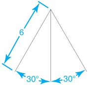
Figure 8-14 A transparent Zoom command
![]() Select the Polar Array tool from the Modify panel on the Home tab of the ribbon.
Select the Polar Array tool from the Modify panel on the Home tab of the ribbon.
![]() Select the two angled lines, and press <Enter>.
Select the two angled lines, and press <Enter>.
![]() Select the bottom endpoint of the middle vertical line when prompted to specify a center point.
Select the bottom endpoint of the middle vertical line when prompted to specify a center point.
![]() Select the Items option.
Select the Items option.
![]() Type 8<Enter> to specify the number of items (copies).
Type 8<Enter> to specify the number of items (copies).
![]() Press <Enter> again to exit the Polar Array tool.
Press <Enter> again to exit the Polar Array tool.
![]() Select the array you just created. The Array context tab of the ribbon is displayed at the top of the drawing window.
Select the array you just created. The Array context tab of the ribbon is displayed at the top of the drawing window.
![]() Change the Items value from 8 to 16 on the top of the Items panel on the left side of the Array context tab of the ribbon. The total number of array objects will update.
Change the Items value from 8 to 16 on the top of the Items panel on the left side of the Array context tab of the ribbon. The total number of array objects will update.
![]() Press the <Esc> key to deselect the array so it is no longer highlighted.
Press the <Esc> key to deselect the array so it is no longer highlighted.
![]() Save your drawing as CH08_EXERCISE4. Your drawing should look like Figure 8-15.
Save your drawing as CH08_EXERCISE4. Your drawing should look like Figure 8-15.

Figure 8-15 A polar array
Trimming and Extending Objects
Trimming and extending are combined in the process of shortening or lengthening objects using AutoCAD objects as the boundaries. When you trim or extend, you use existing AutoCAD objects as the boundary edges, and AutoCAD either lengthens or shortens your objects to touch those edges.
The TRIM and EXTEND commands are located on a small flyout menu on the Modify panel, as shown in Figure 8-16.

Figure 8-16 The Trim/Extend flyout menu
Tip
When using the flyout menu to select either the Trim or Extend tool, the last tool used becomes the default, top-level tool so that you do not need to display the flyout menu the next time you use the same command.
Trimming Objects
Objects are trimmed using the TRIM command. When you start the TRIM command, AutoCAD prompts you to select your cutting edges. These cutting edges determine the stopping boundaries of the trimmed objects. Select the cutting edges using AutoCAD’s standard selection methods. Once you’ve selected the cutting edges, press <Enter>, and AutoCAD will prompt you to select the object to trim. As you pick each object, AutoCAD will trim the object back to the cutting edge. The portion of the object you select is the part that is deleted. In order for an object to be trimmed, it must cross one of the cutting edges. If AutoCAD cannot detect an intersection between the cutting edges and the object to be trimmed, it displays a message: Object does not intersect an edge.
TRIM |
|
|---|---|
Ribbon & Panel: |
Home | Modify |
Menu: |
Modify | Trim |
Command Line: |
TRIM |
Command Alias: |
TR |
Selecting Cutting Edges. In some cases, the cutting edges and the objects to be trimmed may be the same objects. AutoCAD does not distinguish between the cutting edges and the objects to be trimmed. You can select a cutting edge as an object to be trimmed.
Tip
AutoCAD will allow you to select all the drawing objects as cutting edges. To do this, simply press <Enter> when prompted to select the cutting edges. When you do this, AutoCAD will use all the objects in the drawing as cutting edges and simply trim an object to the closest intersecting edge.
Trim Options. After you select the cutting edges, the TRIM command has a number of options. They are listed in the following table.
Fence |
This option allows you to select multiple objects to trim by drawing a fence line. Anything that touches the fence line will be trimmed back to the nearest cutting edge. |
Crossing |
Like the Fence option, this allows you to select multiple objects to trim by drawing a crossing window. Anything that touches the edge of the crossing window is trimmed to its nearest cutting edge. |
Project |
This option is for objects located in different three-dimensional planes. It allows you to trim objects that appear to intersect even though they are in different 3D planes. |
Edge |
The Edge option allows you to trim objects based on an implied intersection with a cutting edge. When this option is selected, you can set the edge mode to Extend or No extend. In No extend mode, an object must actually intersect with a cutting edge in order to be trimmed. With Extend mode, an object will be trimmed as if the cutting edge extended out to infinity (see Figure 8-17). No extend mode is the default setting. |
Erase |
The Erase option allows you to erase objects instead of trimming them. You may find that once you start trimming an object, you simply want to trim it all away. The Erase option allows you to do that within the TRIM command instead of exiting the command and starting the ERASE command. |
Undo |
Undo will undo the last trim action. If you selected a single object to trim, the Undo option will undo that trim. If you used either the Fence or Crossing option to select multiple objects, AutoCAD will undo all the trims done with that selection. |
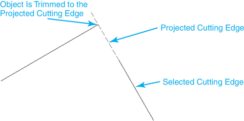
Figure 8-17 Extend mode settings
Some closed objects, such as circles or ellipses, require that the object intersect a cutting edge in at least two places. This is because these objects have no endpoints and must therefore be trimmed between two edges. If you attempt to trim one of these objects with only one cutting edge, AutoCAD will display the message: Object must intersect twice. Some objects cannot be trimmed, such as text and blocks.
Exercise 8-5 Trimming Objects
![]() Start a new drawing using the acad.dwt drawing template.
Start a new drawing using the acad.dwt drawing template.
![]() Draw a circle with a radius of 5.
Draw a circle with a radius of 5.
![]() Draw three lines that are 6 units long, starting at the center of the circle at an angle of 80°, 90°, and 100°, respectively, as shown in Figure 8-18.
Draw three lines that are 6 units long, starting at the center of the circle at an angle of 80°, 90°, and 100°, respectively, as shown in Figure 8-18.
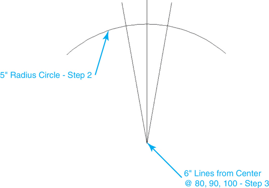
Figure 8-18 5″ Radius circle with 6″ lines from center point
![]() Use the OFFSET command, and offset each line .5 unit, as shown in Figure 8-19.
Use the OFFSET command, and offset each line .5 unit, as shown in Figure 8-19.
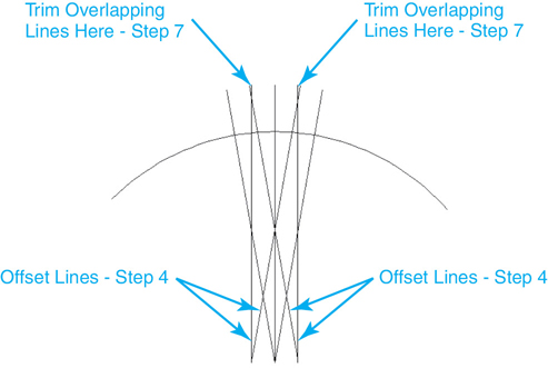
Figure 8-19 Offsetting and trimming lines
![]() Start the TRIM command. AutoCAD prompts you to Select objects or <select all>:.
Start the TRIM command. AutoCAD prompts you to Select objects or <select all>:.
![]() Press <Enter> to select all the objects as cutting edges. AutoCAD prompts you: Select object to trim or shift-select to extend or
Press <Enter> to select all the objects as cutting edges. AutoCAD prompts you: Select object to trim or shift-select to extend or ![]() .
.
![]() Pick the points shown in Figure 8-19 to trim the objects so that all overlapping lines at the corners are cleaned up. AutoCAD continues to prompt you: Select object to trim or shift-select to extend or
Pick the points shown in Figure 8-19 to trim the objects so that all overlapping lines at the corners are cleaned up. AutoCAD continues to prompt you: Select object to trim or shift-select to extend or ![]() .
.
![]() Select the eRase option. AutoCAD prompts you to Select objects to erase:. Select the three vertical lines, the 80° line, and the 100° line that start at the circle center point as shown in Figure 8-19. Press <Enter> to erase the selected objects. Your drawing should look like Figure 8-20.
Select the eRase option. AutoCAD prompts you to Select objects to erase:. Select the three vertical lines, the 80° line, and the 100° line that start at the circle center point as shown in Figure 8-19. Press <Enter> to erase the selected objects. Your drawing should look like Figure 8-20.

Figure 8-20 Drawing after objects trimmed and erased
![]() AutoCAD again prompts you to Select object to trim or shift-select to extend or
AutoCAD again prompts you to Select object to trim or shift-select to extend or ![]() . Press <Enter> or <Esc> to exit the TRIM command.
. Press <Enter> or <Esc> to exit the TRIM command.
![]() Draw two circles with a diameter of 0.3125 by snapping to the endpoints of the angled lines as shown in Figure 8-21.
Draw two circles with a diameter of 0.3125 by snapping to the endpoints of the angled lines as shown in Figure 8-21.
![]() Start the OFFSET command, and offset each of these circles 0.6875 toward the outside of each circle, as shown in Figure 8-21.
Start the OFFSET command, and offset each of these circles 0.6875 toward the outside of each circle, as shown in Figure 8-21.

Figure 8-21 Offsetting and trimming the circles
![]() Zoom in on the two circles at the top of the drawing. Start the TRIM command, and press <Enter> to select all the objects as cutting edges, and then select the six trim points shown in Figure 8-21.
Zoom in on the two circles at the top of the drawing. Start the TRIM command, and press <Enter> to select all the objects as cutting edges, and then select the six trim points shown in Figure 8-21.
![]() Choose the eRase option, and select the objects shown in Figure 8-22 to erase. Press <Enter> to erase the objects. Press <Enter> again to end the TRIM command.
Choose the eRase option, and select the objects shown in Figure 8-22 to erase. Press <Enter> to erase the objects. Press <Enter> again to end the TRIM command.
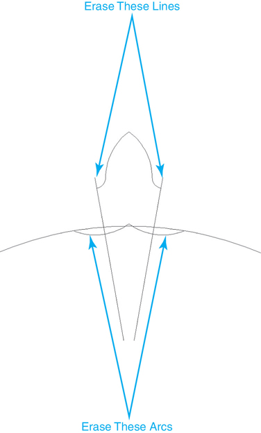
Figure 8-22 Erasing the remaining objects
![]() Save your drawing as CH08_EXERCISE5.
Save your drawing as CH08_EXERCISE5.
Extending Objects
Extending objects is similar to trimming them; the objects simply get longer instead of shorter. The EXTEND command has options similar to the TRIM command except you are prompted to select boundary edges instead of cutting edges. Whether they are called boundary or cutting edges, the concept is the same; the edge determines where the object is extended.
EXTEND |
|
|---|---|
Ribbon & Panel: |
Home | Modify |
Menu: |
Modify | Extend |
Command Line: |
EXTEND |
Command Alias: |
Ex |
Extend Options. The options for the EXTEND command are identical to those for the TRIM command with the exception of the eRase option. Because extending is an additive process (you are adding length to objects) and the eRase option is a subtractive process, this option is omitted from the EXTEND command.
Using the <Shift> Key to Switch Between Trim and Extend. Because the EXTEND and TRIM commands are so similar, AutoCAD provides an easy way to switch back and forth between them. You may have noticed that in the TRIM command, after you select the cutting edges, AutoCAD prompts you to Select object to trim or shift-select to extend or ![]() . By holding down the <Shift> key while selecting the objects to extend, you can use the TRIM command to trim objects. The same is true for the EXTEND command. After you select the boundary edges, AutoCAD prompts you to Select object to extend or shift-select to trim or
. By holding down the <Shift> key while selecting the objects to extend, you can use the TRIM command to trim objects. The same is true for the EXTEND command. After you select the boundary edges, AutoCAD prompts you to Select object to extend or shift-select to trim or ![]() . While the <Shift> key is depressed, the EXTEND command will trim objects, using the boundary edges as the cutting edges.
. While the <Shift> key is depressed, the EXTEND command will trim objects, using the boundary edges as the cutting edges.
Exercise 8-6 Extending Objects
![]() Continue from Exercise 8-5.
Continue from Exercise 8-5.
![]() Start the OFFSET command and offset the large circle 3.5 units toward the center of the circle. Repeat the OFFSET command, and offset the new circle .5 unit toward the center.
Start the OFFSET command and offset the large circle 3.5 units toward the center of the circle. Repeat the OFFSET command, and offset the new circle .5 unit toward the center.
![]() Draw two lines, each 8 units long, from the center of the circle at an angle of 85° and 95°, respectively.
Draw two lines, each 8 units long, from the center of the circle at an angle of 85° and 95°, respectively.
![]() Draw two more short lines, each 3 units long, from the center of the circle at an angle of 60° and 120°, respectively.
Draw two more short lines, each 3 units long, from the center of the circle at an angle of 60° and 120°, respectively.
![]() Start the OFFSET command, set the eRase option to Yes so the original lines are erased, and set the offset distance to .25. Offset the two short lines. Offset the left-hand line to the right, and the right-hand line to the left. Your drawing should look like Figure 8-23.
Start the OFFSET command, set the eRase option to Yes so the original lines are erased, and set the offset distance to .25. Offset the two short lines. Offset the left-hand line to the right, and the right-hand line to the left. Your drawing should look like Figure 8-23.

Figure 8-23 Angled lines with offsets
![]() Zoom in on the top of the drawing, and start the EXTEND command. AutoCAD prompts you to Select objects or <select all>:. Select the two 8″–long angled lines, and press <Enter> to make them the boundary edges.
Zoom in on the top of the drawing, and start the EXTEND command. AutoCAD prompts you to Select objects or <select all>:. Select the two 8″–long angled lines, and press <Enter> to make them the boundary edges.
![]() AutoCAD prompts you to Select object to extend or shift-select to trim or
AutoCAD prompts you to Select object to extend or shift-select to trim or ![]() . Pick the two small arc segments nearest to the angled lines selected in step 6 as shown in Figure 8-24 so that the arcs extend out to meet the boundary edges.
. Pick the two small arc segments nearest to the angled lines selected in step 6 as shown in Figure 8-24 so that the arcs extend out to meet the boundary edges.
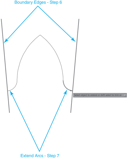
Figure 8-24 Extending the arcs
![]() Select the ERASE command, and delete the two 8″–long angled lines used as boundary edges in step 7.
Select the ERASE command, and delete the two 8″–long angled lines used as boundary edges in step 7.
![]() Zoom out to see the entire drawing, and select the EXTEND command again. Select the two outer circles and the two angled lines as boundary edges as shown in Figure 8-25, and press <Enter>.
Zoom out to see the entire drawing, and select the EXTEND command again. Select the two outer circles and the two angled lines as boundary edges as shown in Figure 8-25, and press <Enter>.
![]() Pick near the ends of the two angled lines using the pick points shown in Figure 8-25 to extend the lines to meet the outer circle.
Pick near the ends of the two angled lines using the pick points shown in Figure 8-25 to extend the lines to meet the outer circle.
![]() Hold down the <Shift> key to enter Trim mode. Select the inner circle using the pick point shown in Figure 8-25, and trim it into the small arc segment shown in Figure 8-26.
Hold down the <Shift> key to enter Trim mode. Select the inner circle using the pick point shown in Figure 8-25, and trim it into the small arc segment shown in Figure 8-26.
![]() Hold down the <Shift> key to enter Trim mode. Select the two angled lines using the pick points shown in Figure 8-25, and trim them to meet the small arc segment created in step 11 as shown in Figure 8-26.
Hold down the <Shift> key to enter Trim mode. Select the two angled lines using the pick points shown in Figure 8-25, and trim them to meet the small arc segment created in step 11 as shown in Figure 8-26.
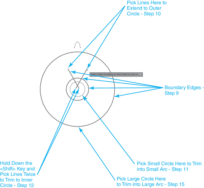
Figure 8-25 Using the <Shift> key to switch between EXTEND and TRIM

Figure 8-26 Drawing after trimming/extending lines and arcs
![]() Press <Enter> to end the EXTEND command.
Press <Enter> to end the EXTEND command.
![]() Start the TRIM command, and select the two angled lines that were extended in step 10 as cutting edges and press <Enter>.
Start the TRIM command, and select the two angled lines that were extended in step 10 as cutting edges and press <Enter>.
![]() Pick the outer circle near the bottom as shown in Figure 8-25 to trim it into the large arc segment shown at the top in Figure 8-26.
Pick the outer circle near the bottom as shown in Figure 8-25 to trim it into the large arc segment shown at the top in Figure 8-26.
![]() Press <Enter> to end the TRIM command.
Press <Enter> to end the TRIM command.
![]() Save your drawing. Your drawing should look like Figure 8-26.
Save your drawing. Your drawing should look like Figure 8-26.
Creating Fillets and Chamfers
Fillets and chamfers are rounded and angled corners, respectively. To create a fillet or a chamfer using basic drawing and editing commands would be a difficult task. The process of rounding a simple right-angle corner would involve shortening each leg by the radius of the round, and then creating an arc segment between the two shortened ends. Using TRIM and EXTEND might make the process easier, but you would still need to draw an arc or circle and use a combination of TRIM and EXTEND to clean up the intersections. Creating a chamfered or angled corner might prove easier but would still involve drawing new objects and cleaning up their intersections. The FILLET and CHAMFER commands allow you to easily add rounds and angled lines at the corner of two intersecting objects.
The FILLET and CHAMFER commands are located on a small flyout menu on the Modify panel, as shown in Figure 8-27.
FILLET |
|
|---|---|
Ribbon & Panel: |
Home | Modify |
Menu: |
Modify | Fillet |
Command Line: |
FILLET |
Command Alias: |
F |
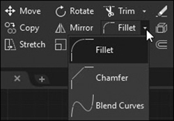
Figure 8-27 The Fillet/Chamfer flyout menu
Note
The Blend Curves tool located at the bottom of the flyout menu shown in Figure 8-27 allows you to create a curved spline in the gap between two selected lines or curves. Please consult AutoCAD Help for more information about spline objects.
Tip
When using the flyout menu to select either the Fillet or Chamfer tool, the last tool used becomes the default, top-level tool so that you do not need to display the flyout menu the next time you use the same command.
Creating Fillets
To create a fillet, you specify a fillet radius and select two objects. AutoCAD will place an arc between the two objects and trim and extend the objects as needed. The points where you select the objects determine where the arc is placed. AutoCAD will place the fillet so that the selected portions will remain (see Figure 8-28).
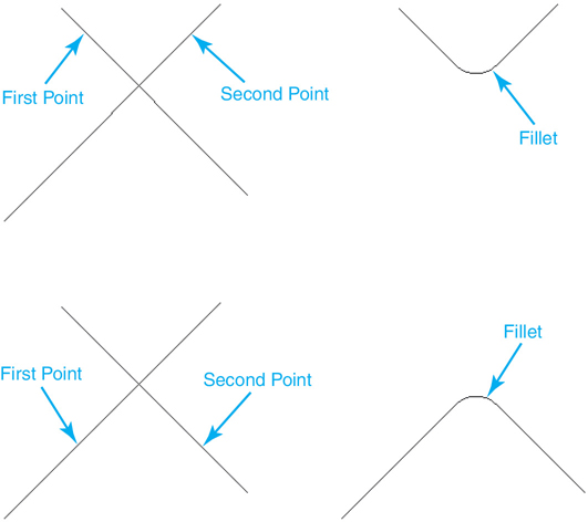
Figure 8-28 Fillet selections
After selecting the first object, AutoCAD provides a preview of the fillet when you pass your cursor over the second object. You can use the Radius option to change the radius value anytime before you select the second object.
Radius Option. When you start the FILLET command, the current radius setting is listed at the command line. The Radius option allows you to set the fillet radius. The fillet radius is stored in the FILLETRAD system variable, and once set AutoCAD will retain the setting until you change it. Setting the Radius option to 0 will result in AutoCAD squaring off a corner.
Note
If you specify a radius that is too large or too small or try to create an arc that cannot be created, AutoCAD will return an error message. Blocks and text cannot be filleted.
Tip
It is possible to create a square corner even if the fillet radius is currently set to a value greater than 0 by holding down the <Shift> key when selecting the second line.
You can create a fillet between open objects (lines, arcs, and elliptical arcs) as well as closed objects (circles and ellipses). When you select a closed object, AutoCAD doesn’t actually trim the closed object but simply draws a tangent fillet arc (see Figure 8-29).
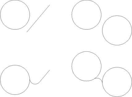
Figure 8-29 Some closed objects with fillets applied
Multiple Mode. The Multiple option puts you into Multiple mode and allows you to create multiple fillets in a single command. In Multiple mode, the FILLET command simply repeats until you press <Enter> or <Esc>. The Undo option allows you to undo the last fillet while in Multiple mode.
Trim Mode. The Trim option allows you to turn Trim mode on and off. With Trim mode turned on, objects are trimmed or extended to the fillet arc. With Trim mode turned off, AutoCAD creates the fillet arc but leaves the source objects unchanged. Like the Radius option, the Trim setting is retained after the FILLET command is complete until you change it.
The Polyline Option. The Polyline option allows you to add a fillet radius to all the intersections in a polyline object.
Capping Two Parallel Lines Using the Fillet Tool
If you fillet two parallel lines, AutoCAD will create a rounded end cap between the two lines. In this case, AutoCAD will ignore the Radius setting and create a 180° arc using half the distance between the lines as the radius. If the lines are different lengths, the first object you select will determine the start point of the arc. The other line will be trimmed or extended to match the first selected object (see Figure 8-30).
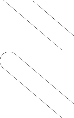
Figure 8-30 Capping two parallel lines
Exercise 8-7 Creating a Fillet
![]() Continue from Exercise 8-6.
Continue from Exercise 8-6.
![]() Start the FILLET command. AutoCAD prompts you to Select first object or
Start the FILLET command. AutoCAD prompts you to Select first object or ![]() .
.
![]() Choose the Multiple option to turn on Multiple mode.
Choose the Multiple option to turn on Multiple mode.
![]() Choose the Radius option and type .5<Enter> to set the fillet radius.
Choose the Radius option and type .5<Enter> to set the fillet radius.
![]() Pick the lines and arc shown in Figure 8-31 to round the outer corners. AutoCAD will round the corners and continue prompting you to select objects.
Pick the lines and arc shown in Figure 8-31 to round the outer corners. AutoCAD will round the corners and continue prompting you to select objects.

Figure 8-31 Creating fillets
![]() Choose the Radius option and type .25<Enter> to set the fillet radius.
Choose the Radius option and type .25<Enter> to set the fillet radius.
![]() Pick the lines and arc shown in Figure 8-31 to round the inner corners. When you’ve finished rounding the four corners, press <Esc> to end the FILLET command.
Pick the lines and arc shown in Figure 8-31 to round the inner corners. When you’ve finished rounding the four corners, press <Esc> to end the FILLET command.
![]() Start the ARRAY command, and create a polar array of the pointed geometry at the top of the drawing. Center the array about the center of the circle, and create 36 items through 360°, rotating the objects as they are copied.
Start the ARRAY command, and create a polar array of the pointed geometry at the top of the drawing. Center the array about the center of the circle, and create 36 items through 360°, rotating the objects as they are copied.
![]() Repeat the ARRAY command, and create a polar array of the rounded wedge. Center the array about the center of the circle, and create six items through 360°, rotating the objects as they are copied. Your drawing should look like Figure 8-32.
Repeat the ARRAY command, and create a polar array of the rounded wedge. Center the array about the center of the circle, and create six items through 360°, rotating the objects as they are copied. Your drawing should look like Figure 8-32.

Figure 8-32 The finished drawing
![]() Save your drawing.
Save your drawing.
Creating Chamfers
The CHAMFER command is used to create angled corners between two intersecting objects. Drawing a chamfer between intersecting objects is similar to drawing a fillet. However, instead of a fillet radius, you need to provide two distances from the intersection along each object, or a distance and an angle for the chamfer (see Figure 8-33).
CHAMFER |
|
|---|---|
Ribbon & Panel: |
Home | Modify |
Menu: |
Modify | Chamfer |
Command Line: |
CHAMFER |
Command Alias: |
CHA |

Figure 8-33 Creating a chamfer
The CHAMFER command has two methods for creating chamfers: distance and angle. The mEthod option allows you to select which chamfer method to use.
After selecting the first object, AutoCAD provides a preview of the chamfer when you pass your cursor over the second object. You can use the Distance or Angle option to change the chamfer size or angle any time before you select the second object.
Tip
It is possible to create a square corner using the CHAMFER command similar to the FILLET command by setting both distances to 0, the default setting. In fact, you can hold down the <Shift> key when selecting the second object and override the distance if it is greater than 0, just like with the FILLET command.
Distance Method. With the Distance method, you specify the distance from the intersection along each line. From the intersection, AutoCAD subtracts the first chamfer distance from the first object and the second chamfer distance from the second object and then draws a line between these two points. The Distance option allows you to set the chamfer distances. The first distance is applied to the first object you select, and the second distance is applied to the second object.
Note
Whereas the FILLET command allows you to create arcs between both straight and curved objects, the CHAMFER command works only on straight, linear objects (lines, straight polyline segments, Xlines, and rays).
If the chamfer distances are equal, a 45° chamfer is drawn. When you set the first distance, AutoCAD sets the default value of the second distance to the first distance. To accept this default, just press <Enter> when prompted for the second chamfer distance.
Angle Method. The Angle method uses a distance and angle to determine the chamfer line. The distance is subtracted from the first object selected to determine the starting point, and the chamfer line is drawn at the specified angle until it intersects with the second object. By default, the angle is measured in a counterclockwise direction from the first object (see Figure 8-34).
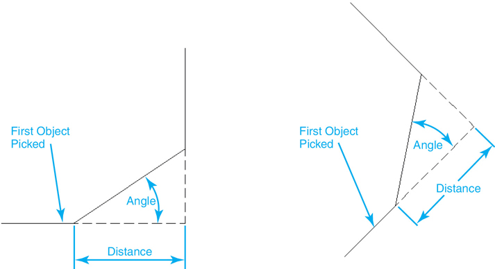
Figure 8-34 The Angle chamfer method
The Polyline Option. The Undo, Polyline, Trim, and Multiple options work the same way as on the FILLET command. When chamfering a polyline with the Polyline option, the first and second objects are determined by the order in which the polyline was drawn. When in doubt, or if you are not getting the results you’re expecting, your best bet may be not to use the Polyline option and just chamfer the polyline segments individually.
Exercise 8-8 Creating a Chamfer
![]() Continue from Exercise 8-2. If you’ve closed the drawing, open drawing CH08_EXERCISE2.
Continue from Exercise 8-2. If you’ve closed the drawing, open drawing CH08_EXERCISE2.
![]() Start the CHAMFER command, and select the Angle option. AutoCAD prompts you to Specify chamfer length on the first line:. Type .75<Enter> to set the length.
Start the CHAMFER command, and select the Angle option. AutoCAD prompts you to Specify chamfer length on the first line:. Type .75<Enter> to set the length.
![]() AutoCAD prompts you to Specify chamfer angle from the first line:. Type 60<Enter> to set the chamfer angle.
AutoCAD prompts you to Specify chamfer angle from the first line:. Type 60<Enter> to set the chamfer angle.
![]() AutoCAD prompts you to Select first line or
AutoCAD prompts you to Select first line or ![]() . Pick the objects shown in Figure 8-35. AutoCAD chamfers the corner. Note that the .75 distance is taken off of the first line you selected.
. Pick the objects shown in Figure 8-35. AutoCAD chamfers the corner. Note that the .75 distance is taken off of the first line you selected.
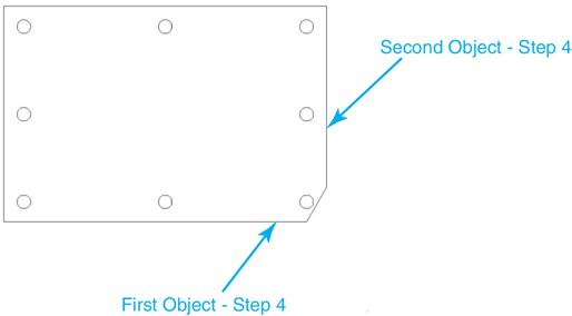
Figure 8-35 Using the Angle method
![]() Because this chamfer comes very close to the hole, type U<Enter> to undo the last chamfer.
Because this chamfer comes very close to the hole, type U<Enter> to undo the last chamfer.
![]() Restart the CHAMFER command, and select the Distance option. Set the first distance to .5. AutoCAD sets the default value of the second distance to match the first. Press <Enter> to accept the default. AutoCAD prompts you to Select first line or
Restart the CHAMFER command, and select the Distance option. Set the first distance to .5. AutoCAD sets the default value of the second distance to match the first. Press <Enter> to accept the default. AutoCAD prompts you to Select first line or ![]() .
.
![]() Select the Multiple option and chamfer the four corners of the part. Your drawing should look like Figure 8-36.
Select the Multiple option and chamfer the four corners of the part. Your drawing should look like Figure 8-36.

Figure 8-36 Creating chamfer
![]() Save your drawing.
Save your drawing.
Breaking an Object
The BREAK command allows you to remove portions of an object or to break a single object into two separate objects. The BREAK command requires you to select an object and then select two points on the object. The portion of the object between the two points is then removed. The BREAK command is located on the expanded Modify panel shown in Figure 8-1.
BREAK |
|
|---|---|
Ribbon & Panel: |
Home | Modify |
Menu: |
Modify | Break |
Command Line: |
BREAK |
Command Alias: |
BR |
Creating a Gap in an Object
When you start the BREAK command, AutoCAD prompts you to select an object. By default, when you select the object, the point you pick on the object becomes the first break point, and AutoCAD will prompt you to select the second break point. If the point you select is not the point you want, you can use the First option to repick the first break point on the selected object.
Once you specify the first break point, AutoCAD prompts you for the second break point and breaks the object between the two points.
Breaking an Object Exactly at a Point
There may be times when you want to break the object in two without creating a physical gap. To break an object without creating an opening, simply use the @ symbol to specify the second point. When you use the @ symbol, AutoCAD will place the second point at the same coordinate as the first point. The end result is the object is broken in two without creating a gap.
Breaking Circles, Xlines, and Rays
Depending on the type of object you select, the BREAK command will create new objects. When you break a line, AutoCAD simply creates two lines. However, when you break a circle, Xline, or ray, AutoCAD will create different types of objects.
Note
Circles and ellipses must be broken in two distinct locations. Using @ when specifying the second break point is not allowed.
Circle. When you break a circle, AutoCAD converts the circle to an arc. The order in which you select the points will determine which portion of the circle is kept. AutoCAD will remove the portion of the circle starting at the first in a counterclockwise direction. Figure 8-37 shows the results of selecting different points along a circle.
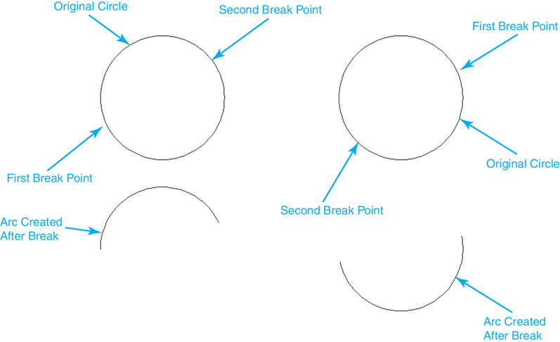
Figure 8-37 Breaking a circle
Xlines and Rays. When you break an Xline, AutoCAD will create two rays with the starting points of the rays located at the first and second break points. Breaking a ray will result in a line and a ray.
Selecting the Second Points
When you select the second break point, there are a couple of things to keep in mind. First, if you select the second point somewhere away from the object, AutoCAD will project a break point along a line perpendicular to the object passing through the selected point. Second, if the second break point lies past the end of the object, AutoCAD will simply remove everything between the first point and the end of the object. Figure 8-38 shows examples of these.
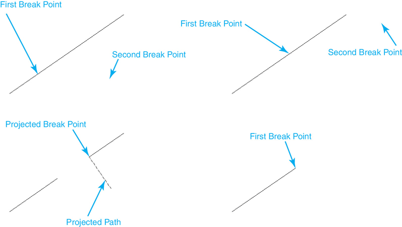
Figure 8-38 Breaking objects
Exercise 8-9 Breaking Objects
![]() Continue from Exercise 8-1. If you’ve closed the drawing, open drawing CH08_EXERCISE1.
Continue from Exercise 8-1. If you’ve closed the drawing, open drawing CH08_EXERCISE1.
![]() Start the BREAK command, and select the circle near the bottom quadrant, between the two vertical lines. AutoCAD prompts you to Specify second break point or
Start the BREAK command, and select the circle near the bottom quadrant, between the two vertical lines. AutoCAD prompts you to Specify second break point or ![]() . Pick anywhere near the circle to break the circle into an arc segment. Don’t worry about the final length of the arc segment.
. Pick anywhere near the circle to break the circle into an arc segment. Don’t worry about the final length of the arc segment.
![]() Restart the BREAK command. AutoCAD prompts you to Select object:. Hold down the <Shift> key, and right-click to bring up the Object Snap menu. Choose Midpoint and select the centerline. This selects the line and places the first break point at the midpoint of the line. AutoCAD prompts you to Specify second break point or
Restart the BREAK command. AutoCAD prompts you to Select object:. Hold down the <Shift> key, and right-click to bring up the Object Snap menu. Choose Midpoint and select the centerline. This selects the line and places the first break point at the midpoint of the line. AutoCAD prompts you to Specify second break point or ![]() .
.
![]() Type @<Enter> to break the line at the midpoint. Drag your cursor over a portion of the centerline. AutoCAD will highlight half of the centerline.
Type @<Enter> to break the line at the midpoint. Drag your cursor over a portion of the centerline. AutoCAD will highlight half of the centerline.
![]() Start the FILLET command, and set the radius to 25. Turn on Multiple mode, and add fillets between the arc and line segments. Your drawing should look like Figure 8-39.
Start the FILLET command, and set the radius to 25. Turn on Multiple mode, and add fillets between the arc and line segments. Your drawing should look like Figure 8-39.

Figure 8-39 Breaking objects
![]() Save your drawing.
Save your drawing.
Joining Multiple Objects
The JOIN command does the opposite of the BREAK command by closing the gap between objects and converting multiple objects into a single object. The JOIN command starts by asking you to select a source object and then prompts you to select the objects to join to the source. The objects you want to join must match the source object and have different rules depending on the type of source object you choose. The JOIN command is located on the expanded Modify panel shown in Figure 8-1.
JOIN |
|
|---|---|
Ribbon & Panel: |
Home | Modify |
Menu: |
Modify | Join |
Command Line: |
JOIN |
Command Alias: |
J |
Tip
It is possible to select and join multiple objects at the same time by selecting them as soon as you start the JOIN command. Typically, you can press <Enter> when prompted to select objects again to quickly join the selected objects in one step.
Lines. When joining lines, all the lines must lie in the same plane and must be collinear. The line segments can overlap or there can be gaps between the line segments, but the end result must be a single, continuous line. Joining multiple line segments results in a single line object.
Arcs. Arcs must lie in the same circular path, meaning they must have the same center point and radius. Like lines, the arcs can overlap or have gaps between them. The end result should be a single continuous arc segment. If the arcs overlap to form a complete circle, AutoCAD will ask you whether you want to convert the arcs into a circle.
You can also use the JOIN command to convert an arc into a circle. When you select an arc as the source object, AutoCAD provides a cLose option. Choosing this option will close the arc and convert it to a circle.
Elliptical Arcs. Elliptical arcs behave the same as circular arcs. The elliptical arcs must lie on the same elliptical path. Gaps and overlaps are allowed, and the cLose option is available to convert an elliptical arc into an ellipse.
Polylines. The objects must be lines, arcs, or open polylines. Gaps and overlapping are not allowed when joining polylines. All the segments must lie end to end in the same plane.
Spline Curves. Spline curves behave similarly to polylines. All the objects must be spline curves that lie in the same plane. Gaps and overlapping are not allowed; all the segments must lie end to end.
Exercise 8-10 Joining Objects
![]() Continue from Exercise 8-9.
Continue from Exercise 8-9.
![]() Start the JOIN command. AutoCAD prompts you to Select source object or multiple objects to join at once:.
Start the JOIN command. AutoCAD prompts you to Select source object or multiple objects to join at once:.
![]() Select one portion of the centerline. AutoCAD prompts you to Select lines to join to source:. Pick the other half of the centerline, and press <Enter>. AutoCAD joins the two lines together.
Select one portion of the centerline. AutoCAD prompts you to Select lines to join to source:. Pick the other half of the centerline, and press <Enter>. AutoCAD joins the two lines together.
![]() Drag your cursor over the centerline to verify that it is a single object.
Drag your cursor over the centerline to verify that it is a single object.
![]() Save your drawing.
Save your drawing.
Lengthening an Object
The LENGTHEN command allows you to lengthen or shorten drawing objects as well as get information about the length of selected objects. When you start the LENGTHEN command, you are asked to select an object and are given four options: DElta, Percent, Total, and DYnamic. When you select an object, the LENGTHEN command displays the length of the object at the command line. If the object is an arc, the included angle of the arc is also displayed. The LENGTHEN command is located on the expanded Modify panel shown in Figure 8-1.
LENGTHEN |
|
|---|---|
Ribbon & Panel: |
Home | Modify |
Menu: |
Modify | Lengthen |
Command Line: |
LENGTHEN |
Command Alias: |
LEN |
Tip
The length information for most objects is displayed in the Properties palette. However, for some objects, such as spline curves, ellipses, and elliptical arcs, the Properties palette doesn’t display total length information. The LENGTHEN command is an easy way to display this information for these complex curves.
The LENGTHEN Command Options
When lengthening an object, AutoCAD must know how much length to add to or subtract from the object. Once it knows what changes to make, the LENGTHEN command will prompt you to select an object to lengthen. You can either select a single object or use the Fence selection method to drag a fence crossing line across the items you wish to lengthen. AutoCAD will keep prompting you to select objects, allowing you to lengthen multiple objects within a single command.
The LENGTHEN command options provide four different methods for altering the length of an object.
DElta Option. The DElta option allows you to specify a discrete length to add to or subtract from the object. When you choose the DElta option, AutoCAD asks you to enter a delta length and then prompts you to select an object. The length you specify is then added to the object at the end closest to where you select. A positive delta value will increase the length, and a negative delta will shorten the object.
The DElta option also includes an Angle option. This allows you to modify the included angle of an arc. By default, positive angles add length in the counterclockwise direction, and negative angles subtract length in the clockwise direction.
Percent Option. The Percent option allows you to scale the line by a percentage value. A percent value of 200 will make an object twice as long. A value of 50 will make it half as long. A value of 110 will add 10% to the length of the object. A value of 100 will leave the object unchanged.
Total Option. The Total option allows you to set the total length of an object. If the value is greater than the current length of the object, the object will increase in length. If the value is smaller, the object will shorten.
DYnamic Option. The DYnamic option allows you to specify the length of an object by dragging it around the screen. When you use this option, you are asked to select an object. AutoCAD will then ask you to specify a new endpoint for the object. You can then drag your cursor around the drawing and dynamically see the length change. To set the length, simply pick a point.
Invalid Objects
When using the LENGTHEN command, it’s possible to ask AutoCAD to create objects that can’t exist or to lengthen objects that cannot be lengthened. For example, although AutoCAD will tell you the length of a closed object like a circle or an ellipse, you can’t add length to a closed object. Another example would be to try to increase the included angle of a line, or to increase the included angle of an arc beyond 360°. In cases such as these, AutoCAD will simply display a message stating that it cannot lengthen the object, and it will ignore the selected object.
Exercise 8-11 Lengthening an Object
![]() Continue from Exercise 8-10.
Continue from Exercise 8-10.
![]() Start the LENGTHEN command, and select the centerline. AutoCAD replies Current length: 100.0000 and prompts you to Select an object or
Start the LENGTHEN command, and select the centerline. AutoCAD replies Current length: 100.0000 and prompts you to Select an object or ![]() .
.
![]() Select the DElta option and enter a value of 25. AutoCAD prompts you to Select an object to change or
Select the DElta option and enter a value of 25. AutoCAD prompts you to Select an object to change or ![]() . Select the bottom portion of each of the vertical lines. Each line is lengthened by 25 units. AutoCAD continues to prompt you to Select an object to change or
. Select the bottom portion of each of the vertical lines. Each line is lengthened by 25 units. AutoCAD continues to prompt you to Select an object to change or ![]() .
.
![]() Type F<Enter> to specify a Fence selection. Draw a fence through the three bottom lines (see Figure 8-40), and press <Enter> to end the selection process. AutoCAD will lengthen the three lines by another 25 units.
Type F<Enter> to specify a Fence selection. Draw a fence through the three bottom lines (see Figure 8-40), and press <Enter> to end the selection process. AutoCAD will lengthen the three lines by another 25 units.
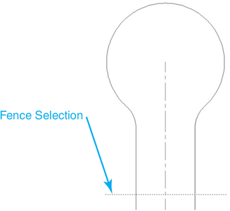
Figure 8-40 Using a Fence selection
![]() Save your drawing. Your drawing should resemble Figure 8-41.
Save your drawing. Your drawing should resemble Figure 8-41.
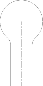
Figure 8-41 The lengthened street
Chapter Summary
The advanced editing techniques explained in this chapter, together with the basic editing techniques introduced in the previous chapter, form the majority of the modification tools and methods used to update AutoCAD 2D drawings. Creating parallel copies of objects using the OFFSET command can be used for many different discipline-specific tasks, be it creating walls in an architectural floor plan or roadways on a civil engineering drawing. The same can be said about rectangular and polar arrays. Using a rectangular array, you can create a column grid layout on an architectural plan in practically one step. Without using a polar array, creating gears and sprockets would be a very time-consuming affair. Path arrays allow you to evenly distribute copies of one or more objects along a linear or curved path a specific number of times or distance.
Trim and Extend tools allow you to quickly “clean up” line work that might have been created as a side effect of some of the other modify and draw tools. Fillet and Chamfer tools can be used to quickly create rounded and beveled corners, as well as to clean up corner work that overlaps or has gaps.
When there is nothing to trim or extend to, the BREAK command allows you to break objects at a single point or create gaps the length you specify. On the flip side, the JOIN command will glue objects back together when they have been broken. If an object is not exactly the correct length, the LENGTHEN command provides a number of different ways to fix it. Contrary to its name, it can be used to shorten objects, too!
Chapter Test Questions
Multiple Choice
Circle the correct answer.
1. Copying an object parallel to an existing object is called:
a. Filleting
b. Chamfering
c. Offsetting
d. Extending
2. In a rectangular array, the row distance represents:
a. The horizontal (X) spacing of the arrayed objects
b. The vertical (Y) spacing of the arrayed objects
c. The number of rows in the array
d. None of the above
3. In the TRIM command, when selecting objects to trim, holding down the <Shift> key:
a. Allows you to remove objects from the selection set
b. Puts a 0 radius corner at the intersection of the two objects
c. Allows you to select additional cutting edges
d. Allows you to extend objects to the cutting edges
4. In the FILLET command, when selecting the objects to fillet, holding down the <Shift> key:
a. Allows you to remove objects from the selection set
b. Puts a 0 radius corner at the intersection of the two objects
c. Allows you to select additional cutting edges
d. Allows you to extend objects to the cutting edges
5. In the TRIM command, when asked to select cutting edges, pressing <Enter>:
a. Ends the TRIM command
b. Switches between EXTEND and TRIM
c. Selects all the objects in the drawing as cutting edges
d. None of the above
6. While creating a rectangular array, the array angle:
a. Rotates the array
b. Changes your rectangular array to a polar array
c. Sets the polar array fill angle
d. None of the above
7. When creating a polar array, entering a negative angle to fill:
a. Will copy objects in a clockwise direction
b. Will copy objects in a counterclockwise direction
c. Is not allowed
d. None of the above
8. The BREAK command:
a. Will work on lines and arcs
b. Will work on closed objects
c. Can have the same first and second break point
d. All of the above
9. To convert an arc to a circle:
a. Use the FILLET command with a 0 radius
b. Use the EXTEND command
c. Use the LENGTHEN command
d. Use the JOIN command
10. Breaking an Xline:
a. Creates a line and a ray
b. Creates two rays
c. Converts the Xline to polyline
d. Is not allowed
Matching
Write the number of the correct answer on the line.
a. ARRAYPATH command ______ |
1. Items copied in a circular pattern |
b. Polar array ______ |
2. Moves objects a user-supplied distance and angle |
c. Fillet radius ______ |
3. Can convert an arc into a full circle |
d. Rectangular array ______ |
4. The radius of a rounded intersection |
e. JOIN command ______ |
5. Copies objects equidistantly along a path |
f. BREAK command ______ |
6. Can convert a circle into an arc and turn a single object into multiple objects |
g. LENGTHEN command ______ |
7. A mode of the OFFSET command that deletes the source object after it is offset |
h. Extend mode ______ |
8. Items copied in a rectangular pattern of rows and columns |
i. Erase mode ______ |
9. A mode of the TRIM and EXTEND commands that allows you to trim or extend to implied intersections |
j. CHAMFER command ______ |
10. Allows you to display and modify the length of objects |
True or False
Circle the correct answer.
1. True or False: The OFFSET command cannot be used on closed objects.
2. True or False: Objects must actually touch each other for the TRIM command to work.
3. True or False: The EXTEND command can be used to trim objects.
4. True or False: A fillet radius can be drawn between two parallel objects.
5. True or False: The JOIN command requires that line segments must lie end to end with no gaps or overlaps.
6. True or False: The LENGTHEN command doesn’t work with arcs.
7. True or False: Holding down the <Shift> key during the CHAMFER command allows it to draw fillet curves.
8. True or False: The eRase option of the TRIM and EXTEND commands will undo any changes made during the command.
9. True or False: The BREAK command requires two separate points when breaking a circle.
10. True or False: The BREAK command converts rays into Xlines.
Chapter Projects
 Project 8-1: Classroom Plan, continued from Chapter 7 [BASIC]
Open drawing P7-1 from Chapter 7.
Draw the remaining equipment and windows shown in Figure 8-42 using the appropriate layers. The windows are all 4′-6″ wide. Do not draw dimensions or text.
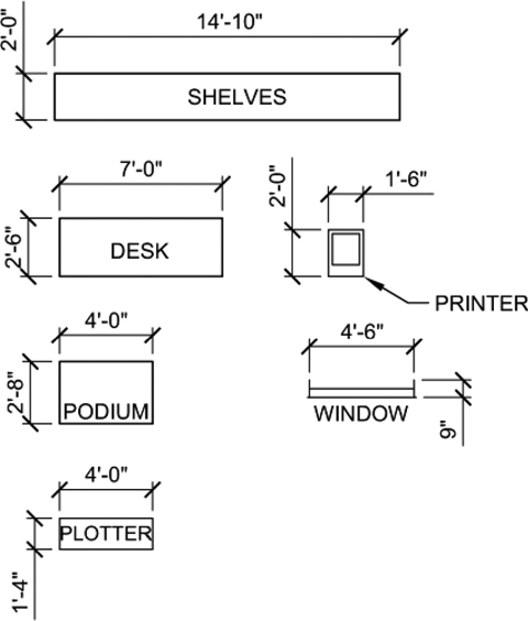
Figure 8-42
Locate the windows as shown in Figure 8-43. Trim the walls as necessary to allow for the window openings. Change the layout of the desks and chairs to reflect the updated plan.
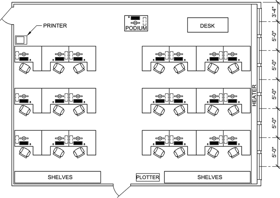
Figure 8-43
Save your drawing as P8-1.
 Project 8-2: Optical Mount—English Units [INTERMEDIATE]
Start a new drawing using the acad.dwt template.
Create the following layers:
Name
Color
Linetype
Lineweight
Description
Object
7
Continuous
0.60 mm
Object lines
Hidden
1
Hidden
0.30 mm
Hidden lines
Center
2
Center
0.30 mm
Centerlines
Hatch
4
Continuous
Default
Hatch patterns and fills
Notes
3
Continuous
0.30 mm
Text and notes
Dims
2
Continuous
Default
Dimensions
Create the three-view drawing as shown in Figure 8-44. Hint: Use the FILLET command to create the round ends of the slots.
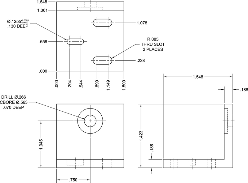
Figure 8-44
Adjust the LTSCALE system so linetypes appear properly.
Do not include notes or dimensions.
Save your drawing as P8-2.
 Project 8-3: Truss with Soffited Eave Detail [ADVANCED]
Start a new drawing using the acad.dwt template.
Set linear units to Architectural with precision set to 1/16″.
Set angular units to Deg/Min/Sec with precision set to 0d00′00″.
Create the following layers:
Name
Color
Linetype
Lineweight
Description
A-Detl-Mbnd
1
Continuous
Default
Detail lines that represent material in the background
A-Detl-Mcut
3
Continuous
0.60 mm
Detail lines that represent material cut in section
A-Detl-P1
2
Continuous
0.30 mm
Secondary (light) lines
A-Detl-Batt
1
Batting
Default
Batt insulation
A-Detl-Pat
1
Continuous
Default
Hatch patterns and fills
A-Anno-Note
3
Continuous
0.30 mm
Note text
A-Anno-Title
3
Continuous
0.30 mm
Title text
A-Anno-Dims
1
Continuous
0.30 mm
Dimensions
Draw all line work that appears beyond the section cut as shown in Figure 8-45 on layer A-Detl-Mbnd (roof truss, break lines, vertical wall lines).

Figure 8-45
Draw all line work that is cut by the section as shown in Figure 8-45 on layer A-Detl-Mcut (lumber in section, plywood, O.S.B., siding).
Draw the X’s that represent lumber in section as shown in Figure 8-45 on layer A-Detl-P1.
Do not include notes or dimensions.
Save the drawing as P8-3.
Project 8-4: 68-Tooth Rear Sprocket—Metric [BASIC]
Start a new drawing using the acadiso.dwt template.
Create the following layers:
Name
Color
Linetype
Lineweight
Description
Object
7
Continuous
0.50 mm
Object lines
Hidden
1
Hidden
0.30 mm
Hidden lines
Center
2
Center
0.30 mm
Centerlines
Hatch
4
Continuous
Default
Hatch patterns and fills
Notes
3
Continuous
0.30 mm
Text and notes
Dims
2
Continuous
Default
Dimensions
Draw the sprocket as shown in Figure 8-46 using the appropriate layers. Hint: Draw one sprocket tooth as indicated in Detail A, and array it using the ARRAY command with the Polar option. You can use the same technique to create the holes.
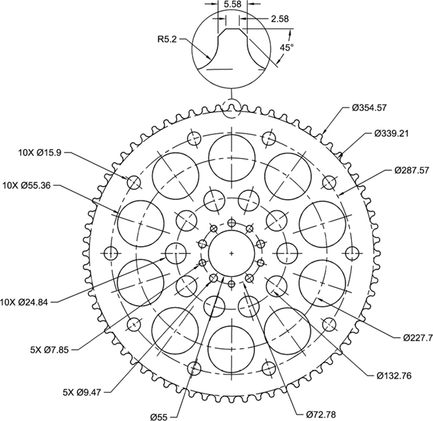
Figure 8-46
Adjust the LTSCALE system so linetypes appear properly.
Do not include notes or dimensions.
Save the drawing as P8-4.
Project 8-5: Residential Architectural Plan, continued from Chapter 7 [ADVANCED]
Open drawing P7-5 from Chapter 7.
Modify the floor plan as shown in Figure 8-47. Use the TRIM, EXTEND, and FILLET commands to clean up wall intersections and door/window openings. Do not draw dimensions or text.
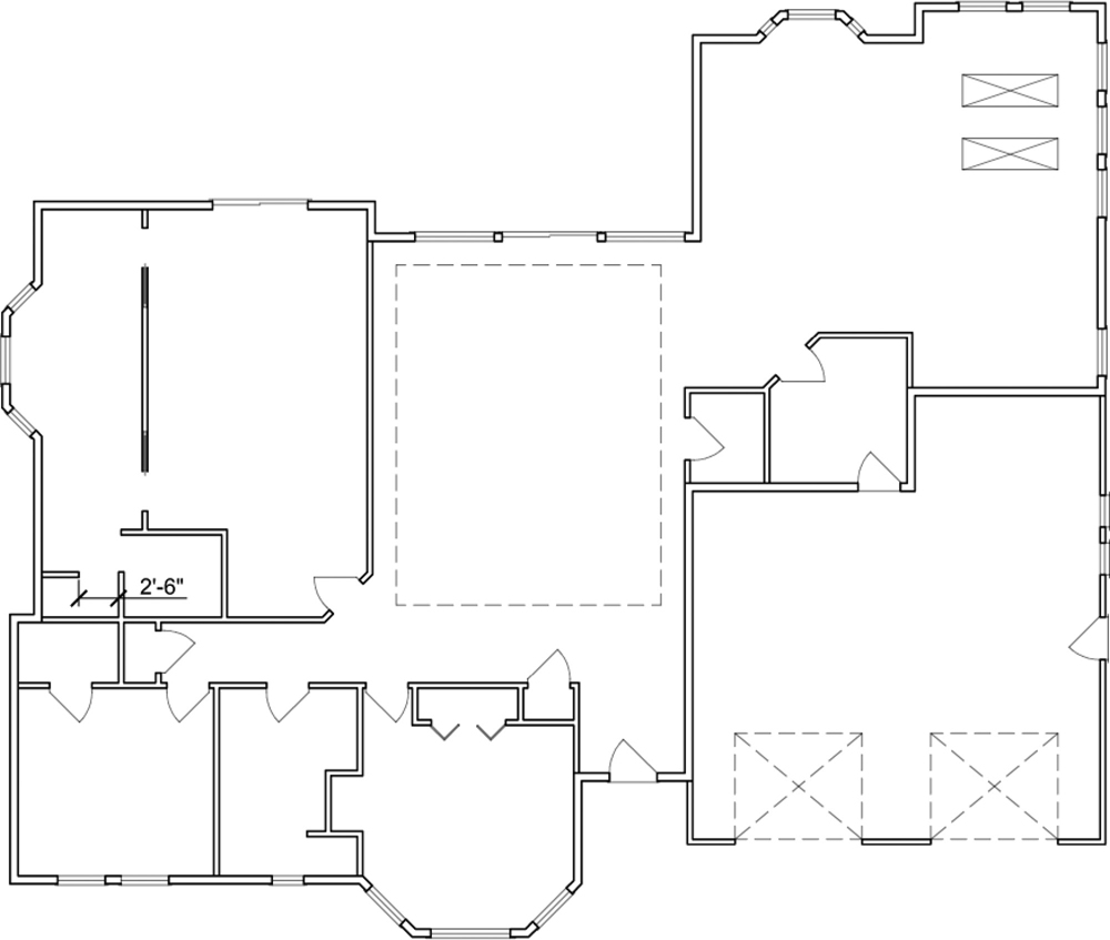
Figure 8-47
Save your drawing as P8-5.