
Chapter Seventeen: Working with External References
Chapter Objectives
Reference an external drawing
Use attachment versus overlay attachment types
Control the path stored with an xref
Load and unload xrefs
Bind an xref
Edit xrefs
Attach raster images
Control the brightness and contrast of a raster image
Use DWF underlays
Use DGN underlays
Use PDF underlays
Use point cloud references
Use coordination model references
Create a transmittal set of drawings
Introduction
Rapidly produced, high-quality drawings are the objective of any drafter or designer. When changes are made to a design, drawings must be updated to reflect the changes. Opening and editing each drawing affected by a change can be a time-consuming process. AutoCAD can help with this process by allowing changes in one drawing to be automatically reflected in other files. This is done through the use of externally referenced drawings, called xrefs.
xref: A drawing that is referenced by another drawing. The drawing references are updated when the source drawing is modified.
When you create an xref, you are placing a reference to another drawing into your drawing. When changes are made to the referenced drawing, your drawing is updated to reflect the changes.
For example, consider the design of a building where multiple people are working on various aspects of the building at once. People working on the HVAC, piping, and electrical systems need to see where the walls, doors, and windows are located. In this situation, the HVAC, piping, and electrical designers could place an xref of the floor plan into their drawings. That way, when changes are made to the floor plan, the xref will update to show those changes, and they can adjust their design as needed.
AutoCAD also allows you to create references similar to raster images. Raster images can enhance your drawing by providing additional visual information to your drawing. Civil or architectural drawings can use an image as a background to locate placement points or structural positions. Satellite or aerial views can be used to trace or locate utilities or roadways. Raster images can also be used to enhance the appearance of your company name or logo. Images are similar to xrefs in that AutoCAD creates a reference to the raster image file. If and when the raster image updates, the changes are automatically reflected in your drawing.
In many design environments, design data can come from many different sources and in different formats. Often, vector drawing data may be provided in a format that you wish to view but not modify. To accommodate this, AutoCAD provides a way to display and view this type of CAD information, called underlays. An underlay is similar to both xref drawings and raster images.
underlay: A CAD file that is not directly modifiable by AutoCAD but is still displayed within a drawing and updated when the source data are changed.
AutoCAD allows you to display DWF (Design Web Format), DGN (MicroStation Design), and PDF (Adobe Portable Document Format) files as underlays. The DWF file format is a compressed vector-based drawing file format developed by Autodesk that allows you to share your drawings with other individuals who do not have AutoCAD and/or who should not have access to sensitive, proprietary design information.
DWF files cannot be modified; they can only be viewed and marked up. Autodesk provides free downloadable software, called Design Review, on its website that allows you to view, mark up, and print DWF files. Another advantage of DWF files is that DWF file sizes are significantly smaller than the original drawing files (DWG) so that they take up less room and can be transferred faster electronically via email or the Internet.
DGN files are vector-based drawing files created by MicroStation, a CAD package similar to AutoCAD. AutoCAD currently supports DGN files created by version 8 (V8) of MicroStation. DGN files cannot be modified by AutoCAD directly; however, AutoCAD can convert DGN files to the DWG file format. AutoCAD can also export drawing data to the DGN file format. See Chapter 18 for more on importing and exporting drawing data.
PDF files, which are also a vector-based format, are the industry standard for sharing electronic information because they can be easily viewed and printed using the free Adobe Reader software that is installed on most computers. Using PDF files, you can share drawings with practically anyone. You can download the Adobe Reader software at www.Adobe.com if you do not have it installed. Although it is not possible to convert a PDF file into the AutoCAD DWG format, you can create PDF files from your AutoCAD drawings. See Chapter 15 for more information about plotting and the procedure for creating PDF files.
In this chapter, we’ll examine xrefs, images, and underlays, the different ways they can be embedded in a drawing, how they are updated, and how to manage and keep track of their relationships.
The Reference Panel
Located on the Insert tab of the ribbon, the Reference panel shown in Figure 17-1 provides most of the tools needed to work with the different types of reference files described above. The Attach tool allows you to create a reference to any of the different file types using one standard file selection dialog box. The Clip tool helps you reduce visual clutter and increase drawing performance by allowing you to “clip,” or cut out, portions of a reference file that do not need to be viewed in your drawing. The Adjust tool allows you to adjust the fade, contrast, and monochrome settings of referenced images and underlays. Other tools allow you to control reference layer settings, decide whether a frame or border is displayed around the edges of a reference, and turn on/off the ability to snap to reference features using AutoCAD’s object snap feature. All these tools and more are covered in detail in the following sections.
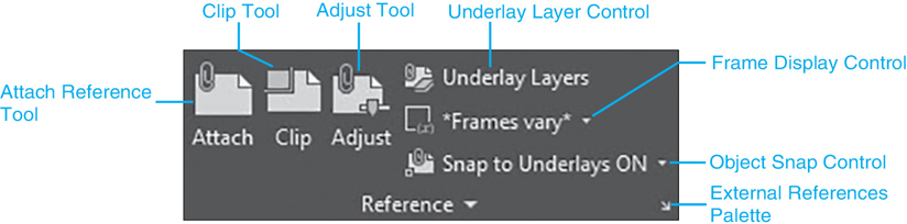
Figure 17-1 The Reference panel
Note
By default, xrefs appear lighter than nonreferenced drawing information so that you can distinguish information that is part of your drawing and can be modified from information that is part of a reference file and cannot be modified unless you open the xref or use one of the xref editing tools explained later.
Tip
The xref fade level can be adjusted using the Xref fading slider control that can be displayed by clicking on the down arrow on the bottom of the Reference panel to display the expanded panel. It is set to 50% by default.
External References Palette
Xrefs, raster images, and underlay files are all managed using the External References palette shown in Figure 17-2. The External References palette can be displayed by selecting the angled down arrow on the right side of the Reference panel shown in Figure 17-1.
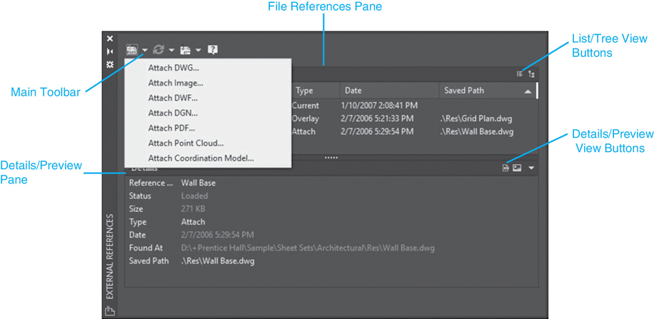
Figure 17-2 The External References palette
The toolbar on the top of the External References palette allows you to create new file references, refresh the status of existing file references, and change reference path options. The button on the left of the toolbar displays a drop-down menu with the following reference attachment options:
External References |
|
|---|---|
Ribbon & Panel: |
Insert | Reference |
Menu: |
Insert | External Reference |
Command Line: |
XREF |
Command Alias: |
XR |
Attach DWG… References another drawing file (DWG) using the XATTACH command
Attach Image… References a raster image file (BMP, JPG, GIF, etc.) using the IMAGEATTACH command
Attach DWF… References a Design Web Format file (DWF) using the DWFATTACH command
Attach DGN… References a DGN file using the DGNATTACH command
Attach PDF… References a PDF file using the PDFATTACH command
Attach Point Cloud… References a point cloud file using the POINTCLOUDATTACH command
Whichever of these attachment options is selected becomes the default button displayed on the toolbar.
The Refresh button updates the status of reference files so that they are current, the Change Path button allows you to change the selected reference(s) path options, and the question mark (?) button displays the AutoCAD Help topic for External References.
The File References pane lists the current drawing, referred to as the master drawing, and any referenced drawings, raster images, or underlays along with their current status, size, type, and the date/time they were last updated. Files can be displayed in the default List View mode (<F3>) or in Tree View mode (<F4>) using the buttons at the top right of the File References pane or their corresponding function keys. The Tree View mode makes it possible to view any nested references and how they are related.
Tip
In the List View mode, you can select two or more files using the standard Windows <Shift> and <Ctrl> key methods.
Right-click shortcut menus provide most of the options for working with the files in the File References pane. If you right-click when no files are selected, a shortcut menu with the following options is displayed:
Reload All References Reloads all referenced files
Select All Selects all file references except the current drawing
Attach DWG… References another drawing using the XATTACH command
Attach Image… References an image file using the IMAGEATTACH command
Attach DWF… References a DWF file using the DWFATTACH command
Attach DGN… References a DGN file using the DGNATTACH command
Attach PDF… References a PDF file using the PDFATTACH command
Attach Point Cloud… References a point cloud file using the POINTCLOUDATTACH command
Tooltip Style Allows you to set the tooltip style shown when you hover your mouse pointer over a reference name to display either the file name of the reference, a graphical preview in one of three sizes, or a list of details as shown in Figure 17-3
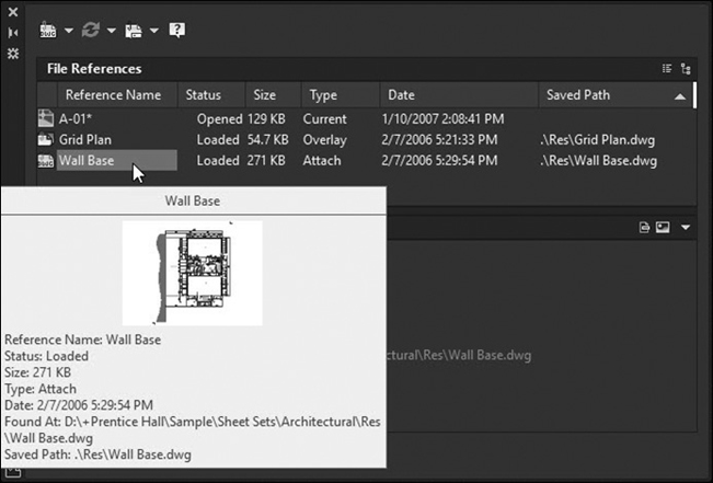
Figure 17-3 Tooltip style set to Details mode
Details/Preview Pane Toggles on and off the Details/Preview pane at the bottom of the palette
Right-clicking when one or more files are selected displays a shortcut menu with some or all of the following options, depending on the file type(s) selected:
Open Opens the selected file reference using the associated application
Attach… Displays the Attach dialog box corresponding to the selected reference type
Unload Unloads the selected file reference
Reload Reloads the selected file reference
Detach Detaches the selected file reference
Bind… Displays the Bind Xrefs dialog box so that you can make an xref part of the current drawing (available only for referenced DWG files)
The Details/Preview pane on the bottom can display either properties for the selected file references or a thumbnail preview if available. Use the buttons on the top right of the Details/Preview pane to switch between the two different modes. The default Details pane displays the following properties for all reference file types:
Reference Name File reference name in drawing. Displays *Varies* if multiple file references are selected (editable)
Status Displays whether file reference is loaded, unloaded, or not found (read-only)
Size Displays the file size of selected file reference (read-only)
Type Indicates whether a DWG file reference is an attachment or overlay, the image file type or underlay (editable for DWG files/read-only for images, DWF, DGN, and PDF files). You can use this property to quickly switch referenced drawings between the Attachment and Overlay attachment types after an xref has been attached without having to detach and reattach it again
Date Displays last date the file reference was modified (read-only)
Found At Displays full path of the selected file reference. This path is where the referenced file is actually found and might not be the same as the Saved Path property below (read-only)
Saved Path Displays the saved path of the selected file reference. This path can be different from where the file was found because of the different options available for locating reference files. If you click in the Saved Path box, the […] button is displayed on the right side of the box. Selecting the […] button displays the Select new path dialog box where you can select a different file or file location. Valid path changes are stored to the Found At property above (editable).
Note
The majority of reference file properties are read-only and cannot be edited unless otherwise noted.
Tip
It is possible to specify a different reference file using the [ … ] button on the right. When you do this, AutoCAD simply references the specified file instead of the file specified in the Reference Name. This allows you to quickly swap one reference file for another.
If you select a referenced raster image file, additional image-specific properties are displayed, such as the image size and resolution. All the additional image properties are read-only and cannot be edited.
The specifics of using the External References palette to reference and manage file types are detailed in the following sections beginning with the first, and arguably the most popular, of the reference file types, external drawing (DWG) references. These are commonly referred to in the industry as xrefs.
Blocks Versus Xrefs
Xrefs are similar to blocks but with a few notable exceptions.
Blocks
When you insert a block, you are creating a reference to a block definition that exists entirely inside the drawing file. When you insert an external drawing file with the INSERT command, AutoCAD converts the external drawing file into an internal block definition. Changes to the original drawing file are not reflected in the drawings containing the inserted blocks.
Xrefs
When you attach an xref, you are directly referencing an external drawing file. Whenever changes are made to the external drawing file, all the references to that drawing are updated as well. Because xrefs point to external drawings, the location of the drawing file (the file path) is important.
Nested Xrefs
Any drawing can be attached as an xref to another xref, a concept known as nesting. To view nested xrefs, select the Tree View button on the File References pane of the External References palette.
It is possible to place a drawing that contains an xref as an xref. For example, say you have a drawing called MASTER that contains a reference to drawing A, and drawing A contains a reference to drawing B (see Figure 17-4). In this example, drawing B is referred to as a nested xref.

Figure 17-4 Nested xrefs
nested xref: An xref within an xref. This occurs when the drawing you are referencing contains a reference to another drawing
Xref nesting can lead to some interesting or unexpected results. In the preceding example, when you reference drawing A, drawing B comes along as a nested xref. However, drawing B could also contain an xref (drawing C), and drawing C might also contain an xref, and the nesting could go on and on. You can also create circular xrefs where drawings reference one another. For example, drawing A could reference drawing B, and drawing B could reference drawing A.
If AutoCAD detects circular xrefs, it will display a warning that circular references are detected (see Figure 17-5) and ask whether you want to continue. If you choose Yes, AutoCAD will break the circular reference and proceed with loading the xref.

Figure 17-5 Circular xrefs warning
Attaching an Xref
When you attach an xref, you create a link to an external drawing file in your drawing. You can attach an xref either by selecting Attach DWG… from the drop-down or right-click menu in the External References palette or via the Attach tool on the Reference panel. Once you’ve selected a drawing, and select OPEN, AutoCAD displays the Attach External Reference dialog box (shown in Figure 17-6).
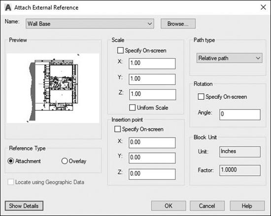
Figure 17-6 The Attach External Reference dialog box
Note
When AutoCAD references a drawing, only model space objects are included. Objects in paper space are ignored.
DWG References |
|
|---|---|
Ribbon & Panel: |
Insert | Reference |
Menu: |
Insert | DWG Reference... |
Command Line: |
XATTACH |
Command Alias: |
XA |
Attachment Versus Overlay
When you attach an xref, you can tell AutoCAD how you want that xref to behave when referenced in other drawings. The Attachment option tells AutoCAD to load this drawing and any nested xrefs. The Overlay option tells AutoCAD to ignore any nested xrefs and load only the top-level drawing.
The Attachment and Overlay options control only how nested xrefs behave when the drawing is referenced in another drawing.
Setting the Path Type
When AutoCAD loads an xref, it must locate the drawing on your computer or network. The file path is the location of the drawing file on your system. It includes the drive letter or server name along with the list of folders and subfolders where the drawing file is located.
When you create an xref, you can tell AutoCAD how you want to store the path to the drawing file. You have the option of saving the Full path, Relative path, or No path.:
Full path If the Path type is set to Full path, AutoCAD stores the entire path, including the local hard drive name or the network location and the entire list of folders and subfolders where the drawing is located. For example, C:DesignProjects8013arch describes the full path to a drawing file. In this example, the xref is located on the local C: drive, in the DesignProjects8013arch folder.
Relative path Using the Relative path option, AutoCAD automatically updates the xref path to assume the current path of the master, or host, drawing so that drive letters and network server names are not a factor as long as the subfolder structure stays the same. AutoCAD replaces the period (.) in the relative path with the path to the master drawing file. For example, if the relative path is set to .Xrefs, the referenced drawings can be located at C:DesignProjects8013Xrefs on one computer or at the network location N:ConsultantsAEC ArchitectsProjects8013Xrefs on another computer. The only requirement is that the master drawing be located in the 8013 folder on both computers so that the subfolder structure is the same.
No path Using No path, AutoCAD will store only the xref drawing name and no path information. When AutoCAD opens the drawing, it will look for the xref in the current drawing folder. If it doesn’t find the xref there, it will then search the folders defined in the AutoCAD Support File Search Path. The Support File Search Path is defined in the Files tab of the Options dialog box. If it still doesn’t find the xref, it will display a note at the command line that the xref cannot be found.
Tip
You can also use the Project Files Search Path setting on the Files tab of the Options dialog box to locate xrefs that rely on the No path option, create a project, and provide one or more paths to search. You must first set the PROJECTNAME system variable to the name of the project you created.
If your drawing files remain at a single location and are never moved or sent to another site, the drawing file paths will remain the same every time you load a drawing file. However, if you send your drawings to others (to a contractor, client, manufacturer, etc.), you need to consider how your drawings will be loaded at these remote sites. Using the Relative path or No path option will make it easier for others to locate the xref drawings.
The REFPATHTYPE variable allows you to controls the default pathing type (0=No path,1=Relative,2=Full)
Insertion Point, Scale, and Rotation
Once you set the reference type and the path type, the rest of the attachment process is identical to inserting a block. The Insertion point, Scale, and Rotation options work exactly like those in the INSERT command. You can specify these values in the dialog box or by selecting them in the drawing.
Manage Xrefs Icon
When xrefs are attached to a drawing, the Manage Xrefs icon is displayed in the system tray in the lower-right corner (see Figure 17-7). Clicking on the icon displays the External References palette, providing a quick way to check xrefs and their status in the current drawing. If an attached xref changes, a notification balloon is also displayed in the system tray, indicating that the xref needs to be reloaded with a link to reload it (see Figure 17-13).
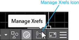
Figure 17-7 The Manage Xrefs icon
Exercise 17-1 Attaching an Xref
![]() Start a new drawing using the Architectural D-size.DWT drawing template located in the student data files.
Start a new drawing using the Architectural D-size.DWT drawing template located in the student data files.
![]() Switch to the Model tab.
Switch to the Model tab.
![]() Create a layer named References, and assign a Continuous linetype and color 7. Set this layer Current.
Create a layer named References, and assign a Continuous linetype and color 7. Set this layer Current.
![]() Select the Insert tab to display the Reference panel, and select the External References button to display the External References palette.
Select the Insert tab to display the Reference panel, and select the External References button to display the External References palette.
![]() Select Attach DWG… from the External References palette toolbar. Select the Grid Plan.dwg located in AutoCAD’s SampleSheet SetsArchitecturalRes folder.
Select Attach DWG… from the External References palette toolbar. Select the Grid Plan.dwg located in AutoCAD’s SampleSheet SetsArchitecturalRes folder.
![]() Set the Reference Type to Attachment. Set the Insertion point to 0,0, the Scale to 1, and the Rotation to 0. Choose OK to place the xref in your drawing. Do a Zoom Extents to see the entire xref.
Set the Reference Type to Attachment. Set the Insertion point to 0,0, the Scale to 1, and the Rotation to 0. Choose OK to place the xref in your drawing. Do a Zoom Extents to see the entire xref.
![]() Select Attach DWG… from the External References palette toolbar again. Select the Wall Base.dwg located in the SampleSheet SetsArchitecturalRes folder.
Select Attach DWG… from the External References palette toolbar again. Select the Wall Base.dwg located in the SampleSheet SetsArchitecturalRes folder.
![]() Set the Reference Type to Attachment. Set the Insertion point to 0,0, the Scale to 1, and the Rotation to 0. Choose OK to place the xref in your drawing. Do another Zoom Extents to see the entire xref.
Set the Reference Type to Attachment. Set the Insertion point to 0,0, the Scale to 1, and the Rotation to 0. Choose OK to place the xref in your drawing. Do another Zoom Extents to see the entire xref.
![]() Save the drawing as CH17_EXERCISE1. Your drawing should resemble Figure 17-8.
Save the drawing as CH17_EXERCISE1. Your drawing should resemble Figure 17-8.
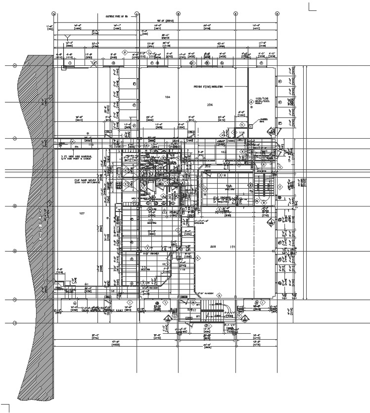
Figure 17-8 The attached xrefs
To access student data files, go to www.pearsondesigncentral.com.
Layers and Xrefs
When you attach an xref to a drawing, all the drawing’s layers come with it. However, AutoCAD distinguishes between layers in the current drawing and layers in an xref by appending the file name along with the pipe (|) character to the layer name. For example, if you reference a drawing called Grid, which contains a layer called S-Grid, AutoCAD will display the layer name as Grid|S-Grid in the Layer Properties Manager palette.
If your drawing contains multiple references to the same drawing file, AutoCAD will assign a number to each reference and append it along with the file name. For example, if you have two references to the drawing Grid in your drawing, AutoCAD will display the layers Grid|1_S-Grid and Grid|2_S-Grid in the Layer Properties Manager palette. The Layer Properties Manager palette also gives you filters for displaying the layers for any given xref.
Changing Xref Layers
The initial state of the xref layers will be the state in which the source drawing was saved. A layer that was frozen in a drawing will initially appear frozen when that drawing is referenced. You can make changes to xref layers, but there are some limitations on what you can do. You cannot set an xref layer as the current layer, and you cannot rename xref layers. However, you can change the color, linetype, lineweight, and visibility of xref layers. This allows you to change how xref layers are displayed and plotted within your drawing.
When you make changes to xref layer settings, AutoCAD will retain any changes to the layer settings the next time the drawing is loaded.
The xref, itself, is inserted on the current layer, so, it is possible to control its visibility, independently. The XREFLAYER variable allows to specify a default xref layer.
Note
You can control the display of layers for objects in xref drawings that are not set to “ByLayer” via the XREFOVERRIDE system variable. If you set XREFOVERRIDE to 1, the xref objects will behave as though their properties are set to “ByLayer.” Setting XREFOVERRIDE to 0 will make xref layers revert back to their original saved settings.
Tip
You can control the retention of xref layer settings with the VISRETAIN system variable. Setting VISRETAIN to 1 tells AutoCAD to retain any changes made to xref layers. Setting VISRETAIN to 0 tells AutoCAD to ignore changes made to xref layers and use the setting stored in the reference drawing each time the reference is loaded. This variable can also be set with the Retain changes to Xref layers box in the Open and Save tab of the Options dialog box.
Exercise 17-2 Xref Layers
![]() Continue from Exercise 17-1.
Continue from Exercise 17-1.
![]() Start the LAYER command. AutoCAD displays the Layer Properties Manager palette.
Start the LAYER command. AutoCAD displays the Layer Properties Manager palette.
![]() Expand the Xref tree in the filters on the left side of the palette. You’ll see the loaded xrefs listed in the tree. Choose the Wall Base xref to show only the layers in that xref.
Expand the Xref tree in the filters on the left side of the palette. You’ll see the loaded xrefs listed in the tree. Choose the Wall Base xref to show only the layers in that xref.
![]() Freeze all the layers that start with Wall Base|1_. Thaw all the Wall Base|2_ layers. Freeze all the Wall Base|2_Arch_Reflected_ Ceiling_Plan_ layers. This isolates the second-floor layers for this building. Choose OK to close the Layer Properties Manager palette.
Freeze all the layers that start with Wall Base|1_. Thaw all the Wall Base|2_ layers. Freeze all the Wall Base|2_Arch_Reflected_ Ceiling_Plan_ layers. This isolates the second-floor layers for this building. Choose OK to close the Layer Properties Manager palette.
![]() Save the drawing. Your drawing should resemble Figure 17-9.
Save the drawing. Your drawing should resemble Figure 17-9.

Figure 17-9 The modified xref layers
Managing Xrefs
The External References palette discussed earlier is the main xref management tool (see Figure 17-10).

Figure 17-10 The External References palette—List View mode
The default list view shows each reference along with its status (loaded or unloaded), file size, attachment type (attach or overlay), file date, and the full path to where the reference is located. The list can be sorted by any column type by selecting the column header at the top of the list as shown in Figure 17-10.
The tree view shows the hierarchy of the loaded xrefs. This allows you to see nested xrefs and their relationship with other xrefs in the drawing as shown in Figure 17-11.

Figure 17-11 The External References palette—Tree View mode
The Right-Click Menu
As mentioned, most of the xref options and settings are provided via a shortcut menu that is displayed when you right-click on an xref in the File References pane as shown in Figure 17-12.
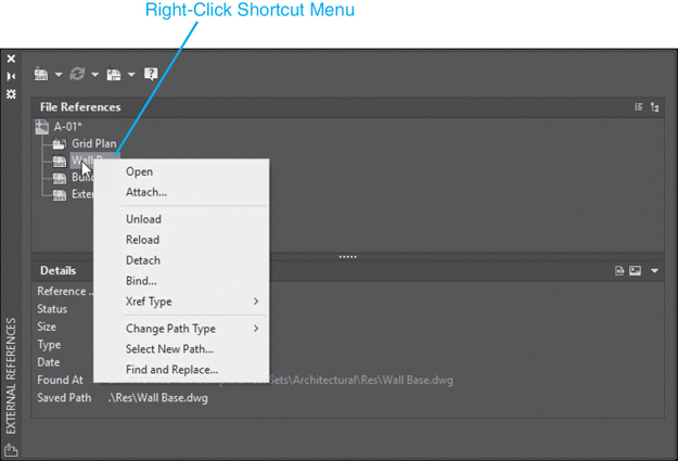
Figure 17-12 The External Reference spalette—right-click menu
Open. The Open menu item will open the selected referenced drawing(s) in a new drawing window. When you select Open, AutoCAD changes the status of the drawing(s) to Opened in the External References palette. This is the same as choosing Open from the File pull-down menu and opening the referenced file directly. The advantage of using Open from the File References pane is that AutoCAD will locate the drawing and open it automatically. It also allows you to open multiple drawings at the same time.
Attach.… The Attach… menu item will display the corresponding attach-type dialog box for the currently selected file type so you can attach another reference file of the same type. This option is unavailable when more than one file is selected.
Unload. The Unload menu item will remove the selected xref(s) from the drawing screen but will retain the reference within the drawing. The xref layers are still retained but the drawing is not displayed.
Reload. The Reload menu item reloads xref(s) in the current drawing. When you reload an xref, AutoCAD reopens the drawing from the location specified in the path. Reloading is necessary when changes are made to an xref while the current drawing is open. The Reload menu item also allows you to reload any unloaded xrefs. Once you reload an xref, the Status column changes to Reloaded. If you have an xref loaded into your drawing and changes are made to the source of the xref, AutoCAD will display a notification balloon (see Figure 17-13) telling you that changes have been made and that reloading is necessary. AutoCAD will also change the status in the File References pane to note that reloading is necessary (see Figure 17-14).
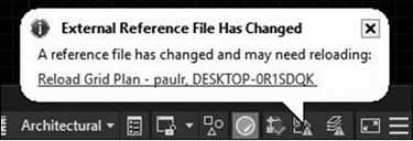
Figure 17-13 The xref notification balloon
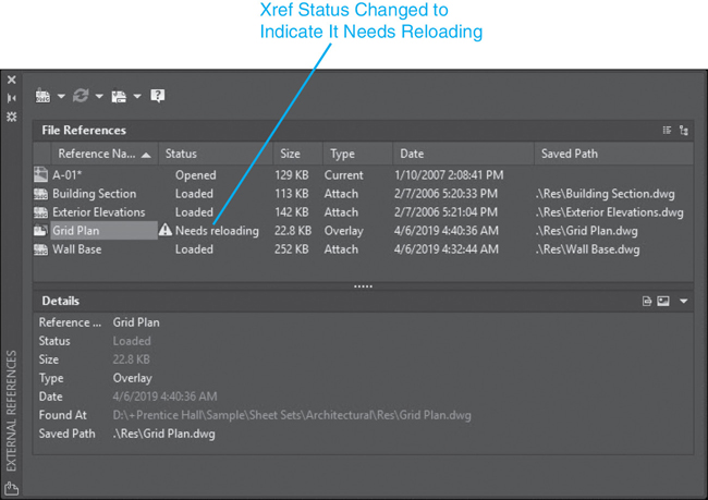
Figure 17-14 The xref status
Detach. The Detach menu item will remove attached xref(s). This completely removes the xref and any nested xrefs from your drawing. All xref layer information is also removed from your drawing.
Bind.… The Bind… menu item converts an externally referenced drawing to an AutoCAD block in the master drawing. When you bind an xref, the xref becomes a permanent part of the current drawing, and any link to the referenced file is broken. The file is removed from the File References pane, and changes made to the original referenced drawing will not be updated. When you bind an xref, you have some options for how to deal with layer names. When you choose the Bind… menu item, AutoCAD displays the Bind Xrefs/DGN underlays dialog box (see Figure 17-15), which allows you to control how the xrefs are bound.
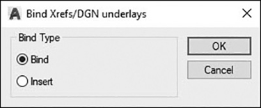
Figure 17-15 The Bind Xrefs/DGN underlays dialog box
The Bind Option. The Bind option binds the selected xref to the current drawing. Xref layers are converted from the format xref|layer to the format xref%n% layer, where the number n is assigned automatically. This allows xref-dependent layers to retain their unique identity.
For example, if you have an xref named FLOOR1 containing a layer named WALL, this layer would appear as FLOOR1|WALL while the drawing is an xref. Once you bind the xref using the Bind option, the layer name is converted to FLOOR1$0$WALL. If the layer FLOOR1$0$WALL already existed, the layer FLOOR1|WALL would be converted to FLOOR1$1$WALL.
Note
Other named objects (i.e., dimension styles, block definitions, text styles, etc.) are renamed in a similar fashion. For example, if the FLOOR1 drawing contained a block named DOOR, the block definition would be renamed FLOOR1$0$DOOR.
Tip
The BINDTYPE system variable controls the default bind type used. When BINDTYPE is set to 0 (the default), object definitions are renamed using the numbering convention. For example, FLOOR1|WALL is converted to FLOOR1$0$WALL. When BINDTYPE is set to 1, object definitions are not renamed, and the xref name is ignored. For example, FLOOR1|WALL is converted to WALL.
The Insert Option. The Insert option binds the xref to the current drawing in a way similar to detaching and inserting the reference drawing as a regular block. Rather than renaming xref layers, the layers are stripped of their xref name and no numbering occurs. If a layer already exists, the layers are simply merged into a single layer, and the layer retains the properties of the existing layer.
Note
If a layer name or other named symbol already exists in the current drawing when a drawing is bound using the Insert type, the original properties are maintained.
For example, if you have an xref named FLOOR1 containing a layer named WALL, after binding it with the Insert option, the xref-dependent layer FLOOR1|WALL becomes layer WALL.
Xref Type. The Xref Type submenu allows you to toggle an xref between the Overlay and Attach xref types.
Path. The Path submenu allows you to remove the full path from an xref or set the path to relative.
Exercise 17-3 Managing Xrefs
![]() Continue from Exercise 17-2.
Continue from Exercise 17-2.
![]() Display the External References palette if it is not already displayed.
Display the External References palette if it is not already displayed.
![]() Select the Grid Plan reference. In the Type property, select Attach and change the attachment type to Overlay. Repeat this for the Wall Base reference.
Select the Grid Plan reference. In the Type property, select Attach and change the attachment type to Overlay. Repeat this for the Wall Base reference.
![]() Select the Wall Base reference, right-click, and select Unload from the shortcut menu. The Status column changes to Unloaded.
Select the Wall Base reference, right-click, and select Unload from the shortcut menu. The Status column changes to Unloaded.
![]() The Wall Base reference drawing is unloaded and disappears from your drawing.
The Wall Base reference drawing is unloaded and disappears from your drawing.
![]() The Wall Base drawing is shown as unloaded but is still referenced in the drawing (see Figure 17-16). Select the Wall Base drawing, and choose Reload from the right-click shortcut menu. The status changes to Loaded.
The Wall Base drawing is shown as unloaded but is still referenced in the drawing (see Figure 17-16). Select the Wall Base drawing, and choose Reload from the right-click shortcut menu. The status changes to Loaded.

Figure 17-16 The unloaded xref
![]() AutoCAD reloads the reference drawing, and it is displayed in its original location.
AutoCAD reloads the reference drawing, and it is displayed in its original location.
![]() Save your drawing.
Save your drawing.
Editing Xrefs
The easiest way to modify an xref is to select it in the drawing so that the External Reference context tab of the ribbon shown in Figure 17-17 is displayed, allowing you to easily access the most useful xref modification tools and controls.
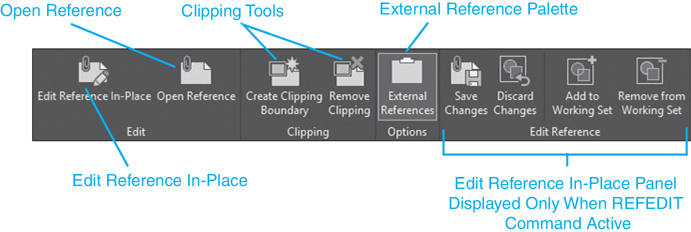
Figure 17-17 The External Reference context tab of the ribbon
The External Reference context tab of the ribbon provides tools to perform the following tasks:
Edit the xref in-place so that you do not have to open the xref drawing file in a separate window.
Open the attached xref in a new AutoCAD drawing window so that you can make any changes and updates as you normally would in AutoCAD, and then save the drawing.
Cut out, or clip, an xref so that only the portion of the xref you need to see is loaded and displayed.
The following sections explore these xref editing tools in detail.
Edit Reference In-Place
It is possible to edit an xref directly within the host drawing. In Chapter 16, you looked at how to use the REFEDIT command to modify block definitions. The REFEDIT command also allows you to modify an xref from within your current drawing. This is known as edit reference in-place.
edit reference in-place: Using the REFEDIT command to make changes to an externally referenced drawing.
Edit In Reference In-Place |
|
|---|---|
Ribbon & Panel: |
External Reference | Edit |
Menu: |
Tools | Xref and Block In-Place Editing | Edit Reference In-Place |
Command Line: |
REFEDIT |
Command Alias: |
None |
Selecting the Edit Reference In-Place tool on the Edit panel on the External Reference context tab of the ribbon displays the Reference Edit dialog box and displays the selected reference drawing along with any blocks or nested xrefs contained in the reference drawing. Selecting the OK button will put you in edit mode so that the reference drawing is no longer one complex block-type object, and you can modify the individual drawing objects using the regular AutoCAD modify commands.
Note
You need to have the proper access privileges to the disk where the reference is stored in order to use the REFEDIT command on an xref. If you are referencing a read-only drawing from a CD or network drive, you will not be able to make changes to the xref.
After you have completed modifying the drawing and you save it, all the host or parent drawings that reference the modified drawing will show the most recent changes when they are opened the next time. If you or someone else has a host or parent drawing that is currently open, a notification balloon should appear in the system tray on the bottom right of the AutoCAD window informing you that the xref has been changed with a link to reload it. Clicking on the link will reload the xref and display the most recent changes.
Tip
To prevent others from using the REFEDIT command to edit your drawing, remove the check from the Allow other users to Refedit current drawing option in the Open and Save tab of the Options dialog box.
Opening Xrefs
Of course, one of the easiest ways to make changes to an xref is to simply open the referenced drawing file with the OPEN command. When you make changes to the referenced drawing and save them, AutoCAD will notify you that changes have been made to the referenced drawing and allow you to update the xref by reloading it.
The Open option on the right-click menu in the External References palette allows you to open referenced drawings directly, bypassing the Select File dialog box. As discussed in the previous section, selecting one or more xrefs in the External References palette and choosing Open from the right-click menu will cause AutoCAD to open each xref in a separate drawing window.
The Open Reference tool on the External Reference context tab of the ribbon also allows you to open referenced drawings directly. Selecting the Open Reference tool simply opens the selected xref. Like the REFEDIT command, saving the xref will ensure that all host drawings that reference the modified file are updated as well.
Open Reference |
|
|---|---|
Ribbon & Panel: |
External Reference | Edit |
Menu: |
Tools | Xref and Block In-Place Editing | Open Reference |
Command Line: |
XOPEN |
Command Alias: |
None |
Exercise 17-4 Editing Xrefs
![]() Continue from Exercise 17-3.
Continue from Exercise 17-3.
![]() Display the External References palette if it is not already displayed.
Display the External References palette if it is not already displayed.
![]() Select the Grid Plan reference and choose Open from the right-click shortcut menu. The status changes to Open.
Select the Grid Plan reference and choose Open from the right-click shortcut menu. The status changes to Open.
![]() AutoCAD opens the Grid Plan.dwg file in a new window.
AutoCAD opens the Grid Plan.dwg file in a new window.
![]() Close the Grid Plan drawing. Do not save any changes.
Close the Grid Plan drawing. Do not save any changes.
Clipping an Xref
There may be times when you want to view only a portion of an xref. The XCLIP command allows you to “clip out” part of the displayed xref. The drawing or xref is not altered, but the xref is clipped to limit the display to only a portion of the xref. Clipping xrefs also speeds up the performance of a drawing. Information that is outside the clipping boundary is not processed by AutoCAD.
When you start the XCLIP command, AutoCAD asks you to select an xref and then presents a number of options. These are described in the following table:
Clip Xref |
|
|---|---|
Ribbon & Panel: |
External Reference | Clipping |
Menu: |
Modify | Clip | Xref |
Command Line: |
XCLIP |
Command Alias: |
XC |
On/Off |
Turns clipping on and off for a given xref. Turning clipping off will cause AutoCAD to ignore any clipping boundaries assigned the xref. |
Clip Depth |
This option is used in 3D xrefs. The Clip Depth allows you to set the viewing depth of 3D models. |
Delete |
Deletes any xclip boundaries associated with an xref. |
Generate Polyline |
Draws a polyline around the edge of an xclip area. When you choose this option AutoCAD will create a polyline along the outline of a clipped xref. Once the polyline is created it has no association with the xref. It is simply a polyline object in the drawing. |
New Boundary |
Defines a new clipping area. If the xref has an existing clipping boundary, AutoCAD will ask you whether you want to delete the old boundary. You then have three methods for defining a new clipping area. |
Select Polyline |
Uses an existing polyline to define a new clipping area. The existing polyline remains after the new clipping area is defined. |
Polygonal |
Allows you to draw a polygon to define the clip area. The polygon does not remain after the clipping area is defined. |
Rectangular |
Allows you to draw a box or rectangle to define the clipping area. The rectangle does not remain after the clipping area is defined. |
Invert Clip |
Inverts the clipping boundary. Clipped objects are shown, and shown objects are hidden. |
Xref clipping is similar to cropping an image in other Windows applications. When you clip an xref, you are simply selecting an area of the xref to display.
It is possible to edit the boundary of a clipped xref using grips to resize the area, as well as invert the clipping area. Before editing a clipping boundary it must first be visible, so you can select it. The easiest way to control the visibility of xref clipping boundaries is via the Reference panel on the Insert tab on the ribbon. Reference clipping boundaries are referred to as frames. By default, frames are hidden and do not display. You can turn them on so they are visible in the drawing by clicking on the Hide frames option on the Reference panel and selecting either the Display and plot frames or the Display but don’t plot frames option from the flyout menu.
Note
You can also change the visibility of an xref clipping boundary by changing the XCLIPFRAME system variable. Setting the XCLIPFRAME variable to 1 makes xref clipping boundaries visible. Setting it to 0 hides xref clipping frames.
Exercise 17-5 Clipping Xrefs
![]() Continue from Exercise 17-4.
Continue from Exercise 17-4.
![]() Start the XCLIP command and select both the Grid Plan and Wall Base drawings and press <Enter>.
Start the XCLIP command and select both the Grid Plan and Wall Base drawings and press <Enter>.
![]() Select the New Boundary option, and then choose Rectangular to create a rectangular clipping boundary.
Select the New Boundary option, and then choose Rectangular to create a rectangular clipping boundary.
![]() Pick the endpoints at P1 and P2 as shown in Figure 17-18. AutoCAD clips the xrefs around the rectangular area.
Pick the endpoints at P1 and P2 as shown in Figure 17-18. AutoCAD clips the xrefs around the rectangular area.
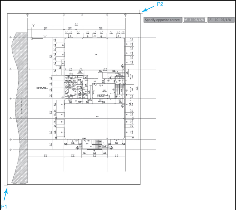
Figure 17-18 Xref clipping area
![]() Save your drawing.
Save your drawing.
Binding Parts of an Xref
Using the Bind… option within the External References palette allows you to bind an entire reference file to your current drawing. This results in the entire drawing being converted to a block and inserted into your drawing. The XBIND command allows you to selectively bind individual named objects (layers, blocks, text styles, etc.) to your current drawing.
Bind |
|
|---|---|
Ribbon & Panel: |
None |
Menu: |
Modify | Object | External Reference | Bind… |
Command Line: |
XBIND |
Command Alias: |
XB |
When you start the XBIND command, AutoCAD displays the Xbind dialog box (see Figure 17-19). The Xrefs area displays all the xrefs in the drawing. Clicking on an xref name will display a list of all the named objects within the xref. To bind an individual object, select the object and choose the Add-> button to add it to the Definitions to Bind list. You can add and remove objects from the list. When you are satisfied with the list of object definitions, choose OK to bind those object definitions to your current drawing.

Figure 17-19 The Xbind dialog box
Demand Loading Xrefs
Demand loading is designed to help make AutoCAD run faster and more efficiently. If you have a number of xrefs loaded, or your referenced drawings are large and complex, you may notice slower system performance. To help with this, AutoCAD uses a method called demand loading.
demand loading: Loading only the visible part of a referenced drawing.
Demand loading works by loading only the parts of an xref that AutoCAD is actually showing. Layers that are turned off or frozen or any geometry hidden by a clipping boundary are not loaded into your drawing until they are needed. When a layer state or a clipping boundary changes, AutoCAD loads the geometry from the referenced drawing. AutoCAD gives you some options for controlling demand loading. These options are found in the Open and Save tab of the Options dialog box (see Figure 17-20).

Figure 17-20 Options for demand load xrefs
Demand loading can be set to Disabled, Enabled, or Enabled with copy. These options are described in the following table:
Disabled |
Turns off demand loading. Each referenced drawing is completely loaded when AutoCAD loads your drawing. |
Enabled |
Turns on demand loading, making AutoCAD run faster and regenerate views quicker. However, the referenced drawings will be locked, preventing others from modifying the referenced drawing while your drawing is open. |
Enabled with copy |
This is AutoCAD’s default setting. AutoCAD will make a temporary copy of any referenced drawings and load this copy into your drawing. This enables demand loading while still allowing other users to modify the referenced drawings. |
The Enabled with copy option provides the benefits of demand loading while still allowing others to work on the referenced drawings. If you use the REFEDIT command while the Enabled with copy option is set, AutoCAD will save the changes back to the original referenced file, not the temporary copy.
Working with Raster Images
Raster images can enhance your drawings in a number of ways. They can provide colorful backgrounds with a company logo or background images for accurately tracing shapes. Architectural and civil drawings can benefit greatly by attaching satellite or aerial images to show site locations or conditions.
These views can then serve as backgrounds to help the reader visualize locations or to help the designer to locate utility points for xrefs or inserts. An image can also help provide vital information about your drawing or the function of your part.
An image can be just about any of the popular raster image formats including BMP, GIF, PNG, TIF, and others. Much like xrefs, the images are simply linked to your drawing so they can be quickly changed, updated, or removed.
Raster images are treated and behave in much the same way as xrefs but have additional controls to regulate image quality and transparency as well as brightness, contrast, and background fading.
Raster Image Reference |
|
|---|---|
Ribbon & Panel: |
Insert | Reference |
Menu: |
Insert | Raster Image Reference… |
Command Line: |
IMAGEATTACH |
Command Alias: |
IAT |
Attaching Raster Images
You can attach a raster image either by selecting Attach Image… from the drop-down or right-click menu in the External References palette (see Figure 17-21) or via the Attach tool on the Reference panel. Once you select an image and choose Open, AutoCAD displays the Attach Image dialog box (see Figure 17-22), which allows you to set the type of path along with the Insertion point, Scale, and Rotation angle. All these functions work the same as the XREF command.
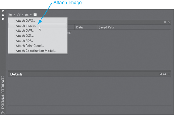
Figure 17-21 The External References palette

Figure 17-22 The Attach Image dialog box
The Show Details button will display information about the resolution and size of the raster image (see Figure 17-23). This will tell you how AutoCAD will convert raster image resolution to physical size. For example, a raster image that has a resolution of 72 pixels per inch, and is 144 pixels by 108 pixels, will be converted to 2″ × 1.5″ in AutoCAD. The Show Details button displays information about the image resolution, AutoCAD units, and the image size in both pixels and AutoCAD units.
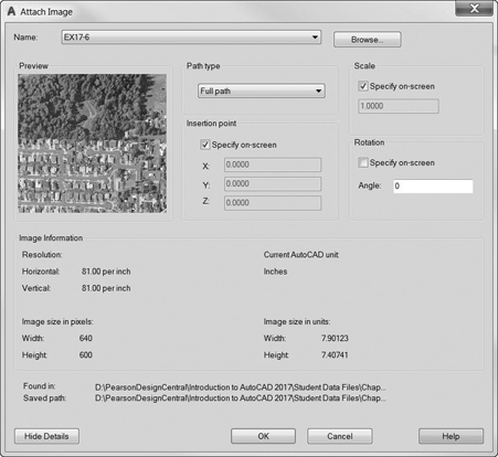
Figure 17-23 Raster image details
Exercise 17-6 Attaching Raster Images
![]() Continue from Exercise 17-5.
Continue from Exercise 17-5.
![]() Switch to the Architectural Title Block layout. Use grips to move and resize the viewport. Set the viewport scale to 1/8″ = 1′-0″.
Switch to the Architectural Title Block layout. Use grips to move and resize the viewport. Set the viewport scale to 1/8″ = 1′-0″.
![]() Display the External References palette if it is not already displayed.
Display the External References palette if it is not already displayed.
![]() Choose Attach Image… and select the image EX17-6.jpg in the student data files. Check the Specify on-screen option for the Insertion point and set the Scale at 2. Choose OK and place the image.
Choose Attach Image… and select the image EX17-6.jpg in the student data files. Check the Specify on-screen option for the Insertion point and set the Scale at 2. Choose OK and place the image.
![]() Save the drawing.
Save the drawing.
To access student data files, go to www.pearsondesigncentral.com.
Managing Images
Once you have loaded images into your drawing, AutoCAD will list the images, their status, file type, file date, and the saved path to the image file. Detach, Reload, and Unload work identically to their xref counterparts. You can also update the Saved Path property via the Found At property on the Details/Preview pane in the External References palette.
Image Adjust |
|
|---|---|
Ribbon & Panel: |
Image | Adjust |
Menu: |
Modify | Object | Image Adjust… |
Command Line: |
IMAGEADJUST |
Command Alias: |
IAD |
Controlling Image Settings
Placing and displaying images can be a somewhat subjective process. The quality, size, and format of raster images can vary widely. AutoCAD provides some tools for controlling and managing raster images.
The easiest way to control an image’s settings and appearance is to select it in the drawing so that the Image context tab of the ribbon shown in Figure 17-24 is displayed, allowing you easy access to the most useful image settings.
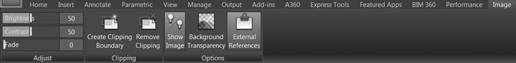
Figure 17-24 The Image context tab of the ribbon
Controlling Image Frames. Before you can select an image in a drawing, you must first turn on the image borders or frames. The easiest way to do that is via the Reference panel on the Insert tab of the ribbon. Click on the Hide frames option, and select either the Display and plot frames or the Display but don’t plot frames option from the flyout menu. The IMAGEFRAME system variable also controls the display of the image outline.
If an image is clipped, it controls the display of the clipping boundary. There are three settings for the IMAGEFRAME variable: 0, 1, and 2. These are described in the following table:
Clip Image |
|
|---|---|
Ribbon & Panel: |
Image | Clipping |
Menu: |
Modify | Clip | Image |
Command Line: |
IMAGECLIP |
Command Alias: |
ICL |
IMAGEFRAME = 0 |
Image frames are not displayed or plotted. |
IMAGEFRAME = 1 |
Image frames are both displayed and plotted. |
IMAGEFRAME = 2 |
Image frames are displayed but not plotted. |
Adjusting Image Brightness, Contrast, and Fade Settings. The Brightness adjustment changes the brightness of an image. This can range from completely black to completely white.
The Contrast adjustment allows you to control the relative difference between dark and light areas of the image.
Note
Many of the image settings discussed in this section can also be controlled via the Image cascade menu located on the right-click menu displayed when an image is selected, as well as in the Properties palette
Image Transparency |
|
|---|---|
Ribbon & Panel: |
Image | Options |
Menu: |
Modify | Object | Image | Transparency |
Command Line: |
TRANSPARENCY |
Command Alias: |
IAD |
The Fade adjustment allows you to blend the image into the background. Moving the Fade control toward the right will adjust the overall color of the image to match the background color. If AutoCAD’s background is set to black, increasing the Fade setting causes the image to fade to black. If the background color is set to white, increasing the Fade setting causes the image to fade to white.
Image Clipping. As with xrefs, you can apply clipping boundaries to images. The Create Clipping Boundary tool allows you to define and control clipping boundaries associated with images. The options are identical to the XCLIP command discussed earlier.
Image clipping boundaries can be modified directly using grips. When you select a clipped image, AutoCAD displays grips at the corners of the clipping boundary. If the clipping boundary is rectangular, moving a grip changes the length and width of the clipping boundary. If the boundary is polygonal, moving a grip will change the shape of the clipping boundary.
Transparency. Some image file formats (such as GIF or PNG) support transparent pixels. When using images with transparency, you can turn the transparency on and off by selecting the Background Transparency button on the Options panel. If your image file format supports transparency, setting it to on will allow objects behind the image to be seen through the transparent pixels in the image.
Exercise 17-7 Controlling Image Settings
![]() Continue from Exercise 17-6.
Continue from Exercise 17-6.
![]() Select the raster image so the Image context tab of the ribbon is displayed.
Select the raster image so the Image context tab of the ribbon is displayed.
![]() Select the Create Clipping Boundary tool on the Clipping panel. Select the Rectangular option, and clip the image as shown in Figure 17-25. Position the image as necessary to match Figure 17-25.
Select the Create Clipping Boundary tool on the Clipping panel. Select the Rectangular option, and clip the image as shown in Figure 17-25. Position the image as necessary to match Figure 17-25.
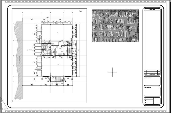
Figure 17-25 The clipped image
![]() Adjust the Brightness and Contrast settings to your liking using the settings on the Adjust panel.
Adjust the Brightness and Contrast settings to your liking using the settings on the Adjust panel.
![]() Save your drawing.
Save your drawing.
Working with DWF Underlays
Remember from the beginning of the chapter that the DWF file format is a compressed vector-based drawing file format that allows you to share your drawings with other individuals who should not have access to sensitive, proprietary design information.
It is possible to reference DWF files in a similar fashion as xref drawings and raster images using the DWF Underlay feature by specifying a file path, insertion point, scale, and rotation angle.
You can modify the appearance of a DWF underlay after it is attached so that it is possible to change the DWF underlay from color-based to monochrome, adjust its fade and contrast, as well as automatically adjust the DWF colors to match the drawing background. It is also possible to define a clipping boundary to limit the visible area of the DWF underlay in a fashion similar to xrefs and images.
Dwf Underlay |
|
|---|---|
Ribbon & Panel: |
Insert | Reference |
Menu: |
Insert | DWF Underlay… |
Command Line: |
DWFATTACH |
Command Alias: |
None |
Attaching DWF Underlays
You can attach a DWF underlay either by selecting Attach DWF… from the drop-down or right-click menu in the External References palette or by selecting the Attach tool on the Reference panel on the Insert tab of the ribbon.
Either method displays the Select Reference File dialog box so you can select a DWF file to attach to your drawing. After you select a file and choose Open, AutoCAD displays the Attach DWF Underlay dialog box shown in Figure 17-26 where you set the type of path along with the Insertion point, Scale, and Rotation angle. These options are the same as those for the XREF command.

Figure 17-26 The Attach DWF Underlay dialog box
If the DWF file consists of multiple sheets, you must select the sheet to attach from the Select one or more sheets from the DWF file: list box on the left.
Managing DWF Underlays
Once you attach one or more DWF underlays in your drawing, AutoCAD will list the DWF file names, their status, file type, file date, and the saved path to the DWF file in the External References palette as shown in Figure 17-27.

Figure 17-27 The External References palette with a DWF underlay attached
Similar to xrefs, most of the DWF underlay options and settings are provided via a right-click shortcut menu similar to the xref shortcut menu shown earlier in Figure 17-12. The DWF underlay options work the same as the xref file options, with a few subtle differences.
Selecting Open from the shortcut menu will open the DWF file using the downloadable Autodesk Design Review software mentioned earlier so that you can view, but not edit, the DWF file.
The Attach… menu item displays the Select DWF File dialog box so that you can attach another DWF file; the other DWF underlay options, Unload, Reload, and Detach work the same as their xref counterparts.
Controlling DWF Underlay Settings
The easiest way to control a DWF underlay’s settings is to select it in the drawing so that the DWF Underlay context tab of the ribbon shown in Figure 17-28 is displayed, allowing you to easily access the most useful DWF underlay settings and options.

Figure 17-28 The DWF Underlay context tab of the ribbon
Controlling DWF Underlay Frames. You can control whether a border outline is displayed around the edges of a DWF underlay via the Hide frames flyout menu on the Reference panel on the Insert tab of the ribbon. Unlike raster images, DWF frames do not need to be on in order to select a DWF underlay. To turn frames on, select either the Display and plot frames or the Display but don’t plot frames option from the flyout menu.
The DWFFRAME system variable also controls the display of the DWF underlay outline. If a DWF underlay is clipped, it controls the display of the clipping boundary. There are three settings for the DWFFRAME variable: 0, 1, and 2. These are described in the following table:
DWFFRAME = 0 |
DWF underlay frames are not displayed and are not plotted. |
DWFFRAME = 1 |
DWF underlay frames are both displayed and plotted. |
DWFFRAME = 2 |
DWF underlay frames are displayed but not plotted (default). |
Adjusting Contrast, Fade Effect, and Color Settings. The options and settings on the Adjust panel allow you to set the contrast, fade effect, and whether a DWF underlay is displayed in color or monochrome.
You have the following options:
Contrast Controls the contrast of the underlay. Values settings are from 0 to 100. The greater the setting, the higher the contrast between dark and light colors, and vice versa. (default = 75)
Fade Controls the fade effect of the underlay. Values settings are from 0 to 80. The higher the setting, the lighter the line work in the underlay. The lower the setting, the darker the line work. (default = 25)
Monochrome Toggles the DWF underlay between color display and monochrome display (black and white). (default = On)
DWF Underlay Clipping. Similar to both xrefs and images, you can apply clipping boundaries to DWF underlays. The Create Clipping Boundary tool allows you to define and control clipping boundaries associated with DWF files. The options are identical to the XCLIP and IMAGECLIP commands.
DWF Clip |
|
|---|---|
Ribbon & Panel: |
DWF Underlay | Clipping |
Menu: |
None |
Command Line: |
DWFCLIP |
Command Alias: |
None |
Adjusting Colors for the Current Background. The Adjust Colors for Background option controls whether the DWF underlay colors are visible against the current drawing background color. The option is accessible only via the Properties palette under the Underlay Adjust category.
The default setting of Yes forces AutoCAD to analyze the background colors of the DWF underlay and the drawing environment to determine whether they are both light or both dark. If necessary, the colors of the DWF underlay are adjusted so the underlay is visible.
If the Adjust Colors for Background option is changed to No, the original colors of the underlay are always used regardless of the current background color. If you use this setting, the DWF underlay might not always be visible.
Turning Object Snaps On and Off. You can control whether object snapping is enabled for the DWF underlay geometry by selecting the Enable Snap button on the DWF Underlay context tab of the ribbon and toggling on or off.
Note
The DWFOSNAP system variable allows you to control whether object snapping to objects that are part of a DWF file is enabled. Setting DWFOSNAP = 1 (default) allows you to snap to DWF underlay objects. Setting DWFOSNAP = 0 turns DWF underlay object snaps off.
Note
You can control layers in other attached xrefs by selecting them in the Reference Name: list box at the top.
DWF Layer Control
When a DWF file is created, the user has the option of including layer information within the DWF file. This allows people viewing the DWF file to turn layers on and off. People viewing the DWF file cannot control the name, color, linetype, etc., of DWF layers, only the layer visibility.
DWF Layers |
|
|---|---|
Ribbon & Panel: |
DWF Underlay | DWF Layers |
Menu: |
None |
Command Line: |
DWFLAYERS |
Command Alias: |
None |
When you attach a DWF underlay, if the DWF file contains layer information, AutoCAD allows you this same ability. The DWFLAYERS command allows you to turn on and off the layers within a DWF file. The DWFLAYERS command is also available by selecting a DWF underlay and choosing DWF Layers… from the right-click menu or the DWF Underlay context tab of the ribbon.
When you start the DWFLAYERS command, AutoCAD will prompt you to select the DWF underlay. If the DWF underlay contains layer information, AutoCAD will display the layer names in the Underlay Layers dialog box (see Figure 17-29). In this dialog box, you can turn DWF layers on and off by clicking the lightbulb icon next to each layer. You can select multiple layers by pressing the <Ctrl> or <Shift> key while clicking layer names. You can also turn layers on and off by right-clicking highlighted layers and choosing Layer(s) On or Layer(s) Off from the right-click menu.
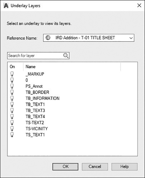
Figure 17-29 The Underlay Layers dialog box
Working with DGN Underlays
Similar to the DWF underlay, AutoCAD supports the referencing of MicroStation V8 DGN design files. Like a DWF underlay, a DGN underlay is a view-only version of the design data contained in the DGN file. DGN underlays are attached in the same way DWF files are, with some minor differences. You can also control the DGN underlay settings via a context ribbon tab and panels that are displayed when you select a DGN file in a drawing.
DGN Underlay |
|
|---|---|
Ribbon & Panel: |
Insert | Reference |
Menu: |
Insert | DGN Underlay… |
Command Line: |
DGNATTACH |
Command Alias: |
None |
Attaching DGN Underlays
You can attach a DGN underlay either by selecting Attach DGN… from the drop-down or right-click menu in the External References palette or by selecting the Attach tool on the Reference panel on the Insert tab of the ribbon.
Either method displays the Select Reference File dialog box so you can select a DGN file. After you select a file and choose Open, AutoCAD displays the Attach DGN Underlay dialog box, shown in Figure 17-30, where you set the type of Path Type along with the Insertion point, Scale, and Rotation angle.

Figure 17-30 The Attach DGN Underlay dialog box
Unlike AutoCAD, which has only one model design space, DGN files can contain multiple design models. Select the desired design model from the Select a design model from the DGN file: list. Only a single design model can be displayed per underlay. Sheet models within a DGN file (similar to DWF sheets) are not listed.
The Conversion Units area of the dialog box allows you to control how units are converted in the DGN file. DGN files use working units (imperial or metric) called master units and subunits. Some number of subunits is equal to one master unit. Select the unit you wish to use in your AutoCAD drawing. For example, if master units are set to feet and subunits are set to inches, then 12 subunits would equal 1 master unit (feet). Selecting Master units in the Conversion Units area would convert DGN master units (feet) to AutoCAD’s unit of measurement.
The Insertion point, Scale, and Rotation settings are the same as those for xrefs and DWF underlays.
Managing DGN Underlays
Once you attach one or more DGN underlays in your drawing, AutoCAD will list all of them along with all the other xrefs, images, and DWF underlays in the External References palette.
Like DWF underlays, the different DGN underlay options and settings are provided via a right-click shortcut menu. The DGN underlay options work exactly the same as their DWF underlay counterparts with some slight differences.
The Open option from the shortcut menu is not selectable. This is because AutoCAD does not include a DGN file viewer with AutoCAD.
The Attach… menu item displays the Select DGN File dialog box so that you can attach another DGN file; all the other DGN underlay options—Unload, Reload, and Detach—work exactly the same as their xref counterparts and DWF underlay.
Dgn Clip |
|
|---|---|
Ribbon & Panel: |
DGN Underlay | Clipping |
Menu: |
None |
Command Line: |
DGNCLIP |
Command Alias: |
None |
Controlling DGN Underlay Settings
The easiest way to control a DGN underlay’s settings is to select it in the drawing so that the DGN Underlay context tab of the ribbon shown in Figure 17-31 is displayed, allowing you to easily access the most useful DGN underlay settings and options.
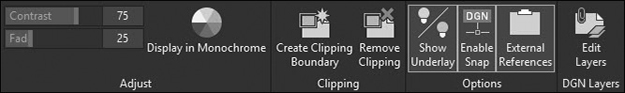
Figure 17-31 The DGN Underlay context tab of the ribbon
DGN underlays share all the same settings and options as DWF underlays, so that you can do the following:
Adjust the contrast, fade, and monochrome settings
Clip portions of a DGN underlay so it is not displayed
Enable/disable object snapping to the DGN underlay geometry
Turn on/off DGN underlay layers if they are included
Refer to the earlier “Controlling DWF Underlay Settings” section for detailed descriptions of all the DGN underlay options.
Working with PDF Underlays
AutoCAD also supports the referencing of PDF (Adobe Portable Document Format) files, the de facto standard for sharing electronic information. PDF underlays are attached using basically the same methods as DGN files. You can also control the PDF underlay settings after it is attached by selecting it in your drawing to display a context tab of the ribbon with the same settings and options as a DGN underlay.
PDF Underlay |
|
|---|---|
Ribbon & Panel: |
Insert | Reference |
Menu: |
Insert | PDF Underlay |
Command Line: |
PDFATTACH |
Command Alias: |
None |
Attaching PDF Underlays
You can attach a PDF underlay either by selecting Attach PDF… from the drop-down or right-click menu in the External References palette or by selecting the Attach tool on the Reference panel on the Insert tab of the ribbon.
Either method displays the Select Reference File dialog box so you can select a PDF file. After you select a file and choose Open, AutoCAD displays the Attach PDF Underlay dialog box shown in Figure 17-32 where you set the Path Type along with the Insertion point, Scale, and Rotation angle.
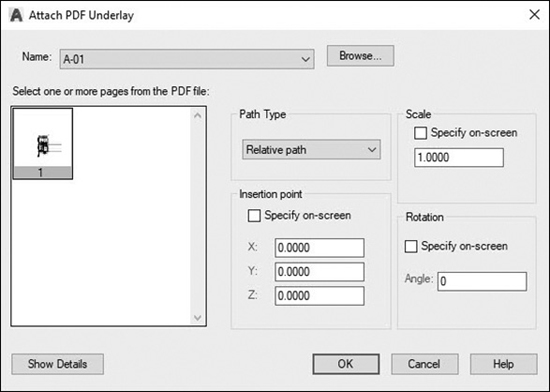
Figure 17-32 The Attach PDF Underlay dialog box
PDF files with more than one page are attached one page at a time (as opposed to one sheet at a time for DWF files or one model at a time for DGN files). If the PDF file has more than one page, you must select the desired page from the Select one or more pages from the PDF file: list.
The Insertion point, Scale, and Rotation settings work the same as for the other types of underlays.
Note
Hypertext links in PDF files are converted to straight text, and digital signatures are not supported.
Managing PDF Underlays
Once you attach one or more PDF underlays in your drawing, AutoCAD will list them along with all the other xrefs, images, and underlays in the External References palette.
Like the other underlays, the different PDF underlay options and settings are provided via a right-click shortcut menu.
Controlling PDF Underlay Settings
The easiest way to control a PDF underlay’s settings is to select it in the drawing so that the PDF Underlay context tab of the ribbon shown in Figure 17-33 is displayed, allowing you to easily access the most useful PDF underlay settings and options.

Figure 17-33 The PDF Underlay context tab of the ribbon
PDF underlays share all the same settings and options as DGN underlays so that you can do the following:
PDF Clip |
|
|---|---|
Ribbon & Panel: |
PDF Underlay | Clipping |
Menu: |
None |
Command Line: |
PDFCLIP |
Command Alias: |
None |
Adjust the contrast, fade, and monochrome settings
Clip portions of a PDF underlay so it is not displayed
Enable/disable object snapping to the PDF underlay geometry
Turn on/off PDF underlay layers if they are included
Refer to the “Controlling DGN Underlay Settings” section earlier for detailed descriptions of all the PDF underlay options.
Working with Point Cloud References
A point cloud is a large collection of 3D points typically generated by a laser scanner that is an accurate 3D representation of existing physical objects such as building exteriors and interiors, site topographies, manufactured parts, and countless other real-world objects.
A point cloud file can be referenced or inserted into an AutoCAD drawing so it can be used as a background. Before you can use raw point data, the data must be converted to readable point cloud files using Autodesk ReCap. Autodesk ReCap converts raw scan data to scan files (RCS), and project files (RCP) that reference multiple RCS files, which can then be attached to an AutoCAD drawing.
Attaching Point Cloud References
You can attach a point cloud reference either by selecting Attach Point Cloud… from the drop-down or right-click menu in the External References palette or by selecting the Attach tool on the Reference panel on the Insert tab of the ribbon.
Either method displays the Select Point File dialog box so you can select a point cloud file. After you select a file and choose Open, AutoCAD displays the Attach Point Cloud dialog box shown in Figure 17-34 where you set the Path Type along with the Insertion point, Scale, and Rotation angle.
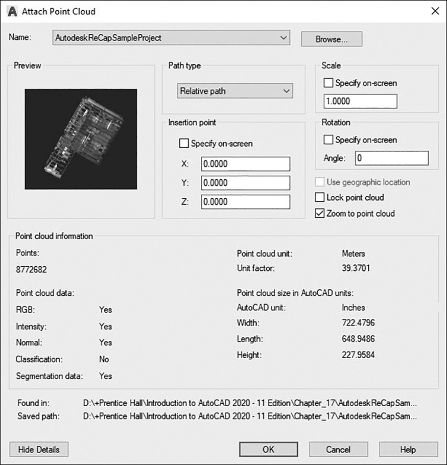
Figure 17-34 The Attach Point Cloud dialog box
Point Cloud Reference |
|
|---|---|
Ribbon & Panel: |
Insert | Reference |
Menu: |
Insert | Point Cloud Reference |
Command Line: |
POINTCLOUDATTACH |
Command Alias: |
None |
The Insertion point, Scale, and Rotation settings work the same as for the other types of underlays/references.
The other available options are as follows:
Use geographic location Inserts the point cloud based on the geographic data in both the point cloud file and the drawing file
Lock point cloud Controls whether an attached point cloud can be moved or rotated
Zoom to point cloud Automatically zooms to the extents of the attached point cloud object
Controlling Point Cloud References
The easiest way to control a point cloud reference’s settings is to select it in the drawing so that the Point Cloud context tab of the ribbon shown in Figure 17-35 is displayed, allowing you to easily access the most useful point cloud settings and options.

Figure 17-35 The Point Cloud context tab of the ribbon
A number of controls and options are available for point cloud data:
Display panel Allows you to manage program performance and visual noise by increasing or decreasing the number of visible points and point size; switch to a perspective view; and navigate around the point cloud
Visualization panel Allows you to analyze features within a point cloud, making it possible to retain the original scan colors or stylize the point cloud based on object color, normals (point orientation), intensity, elevation, or LAS classification data. Provides options to control lighting, shading, the light source, and transparency
Cropping panel Allows you to crop rectangular, polygonal, or circular areas to show only relevant portions of the point cloud
Section panel Allows you to create standard and user-defined 2D planar views of the point cloud data
Extract panel Allows you to extract several types of geometry that can be inferred from a segmented point cloud:
Line corresponding to the edge between two planar segments
Intersection between three planar segments
Centerline of a detected cylindrical segment
Options panel Allows you to display the Point Cloud Manager palette described below and toggle the main External References palette on/off
Managing Point Cloud References
The Point Cloud Manager shown in Figure 17-36 allows you to control display of point cloud projects, regions, and scans so you can isolate different regions of the point cloud display, turn them on/off, and switch to the original vantage point of the camera location for a scan.

Figure 17-36 The Point Cloud Manager palette
Point Cloud Manager |
|
|---|---|
Ribbon & Panel: |
Point Cloud | Options |
Menu: |
None |
Command Line: |
POINTCLOUD-MANAGER |
Command Alias: |
None |
The Tree View and List View buttons allow you to toggle between a hierarchical tree view and a list view.
Scan information is organized in the List/Tree View window as follows:
Project Lists project files that have been attached to the current drawing
Regions Lists the regions that have been defined in Autodesk ReCap Pro for the attached point cloud. Select the region names to highlight them in their assigned color
Unassigned Points Identifies and hides unassigned points or sections of the point cloud that have not been assigned to regions. Select the row to show the unassigned points
Scans Lists the individual scan files that are included in the composite point cloud. Select the row to highlight the points included in the scan. A tag is temporarily displayed in the scene to identify the location
To hide a region or scan, simply click the round button on the right end of the row or use the right-click menu.
Tip
Double-click a scan in the Point Cloud Manager to view the point cloud from the vantage point of the original camera location.
Working with Coordination Model References
A coordination model is a model used for virtual coordination of various trades through the preconstruction and construction phases of a project. It specifically refers to an NWD or NWC file. NWD and NWC are native file formats of Autodesk Navisworks.
Attaching Coordination Model References
You can attach a coordination model reference either by selecting Attach Coordination Model… from the drop-down or right-click menu in the External References palette or by selecting the Attach tool on the Reference panel on the Insert tab of the ribbon.
Either method displays the Select Coordination Model dialog box so you can select a coordination model file. After you select a file and choose Open, AutoCAD displays the Attach Coordination Model dialog box shown in Figure 17-37 where you set the Path Type along with the Insertion point, Scale, and Rotation angle.

Figure 17-37 The Attach Coordination Model dialog box
Coordination Model Reference |
|
|---|---|
Ribbon & Panel: |
Insert | Reference |
Menu: |
None |
Command Line: |
COORDINATION-MODELATTACH |
Command Alias: |
None |
The Insertion point, Scale, and Rotation settings work the same as for the other types of underlays/references.
The other available options are as follows:
Show Current Drawing Geometry in Model Controls the display of the geometry on the current drawing if the current drawing is part of the coordination model
Zoom to Coordination Model Controls whether to zoom in to the coordination model after it is attached
Controlling Coordination Model References
The easiest way to control a coordination model reference’s settings is to select it in the drawing so that the Coordination Model context tab of the ribbon shown in Figure 17-38 is displayed, allowing you to easily access the most useful coordination model settings and options.

Figure 17-38 The Coordination Model ontext tab of the ribbon
The controls and options available for coordination models are as follows:
Display panel Allows you to control color and opacity fading and navigate around the coordination model
Manage panel Allows you to toggle the main External References palette on/off
Transmitting Drawings with References
When creating drawings that use referenced drawings or images, it’s important to consider what happens to those drawings when they are given to others (clients, contractors, vendors, etc.). When you provide drawings to others, any referenced files must be supplied as well. This can be a difficult task when there are multiple references stored in different locations. The problem is compounded if nested xrefs are used.
Fortunately, AutoCAD provides the ETRANSMIT command to help manage these external files. The ETRANSMIT command helps solve the problem of sending incomplete files by compiling all external files into a separate folder or ZIP file. You can also create an email and automatically attach the files to the email.
Using eTransmit
Before using the ETRANSMIT command, you need to save any changes to your drawing. If you start the command before you save any changes, AutoCAD will ask you to save the changes before continuing (see Figure 17-39).

Figure 17-39 The Save Changes notification
Etransmit |
|
|---|---|
Ribbon & Panel: |
Publish | eTransmit |
Menu: |
File | eTransmit… |
Command Line: |
ETRANSMIT |
Command Alias: |
None |
Selecting Files. When you start the ETRANSMIT command, AutoCAD displays the Create Transmittal dialog box (see Figure 17-40). The Files Tree tab shows you a hierarchical tree view of your drawing and any files that are associated with it. From this view, you can see the relationships of the files and also which files are attached to which.

Figure 17-40 The Create Transmittal dialog box
The Files Table tab (see Figure 17-41) shows you a flattened list of all files associated with your drawing. This view does not show file relationships but may be easier to work with because all the files are displayed in a single list.
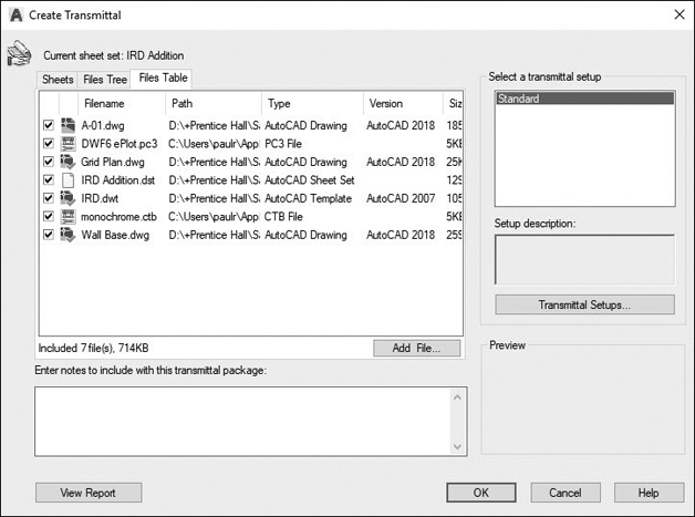
Figure 17-41 The Files Table tab
With either view, you can select the files you wish to include in your transmittal by checking or unchecking the box next to the file.
The Add File… button allows you to specify additional files you wish to include in your transmittal, such as design specifications, product data sheets, or cover letters.
The Transmittal Report. When you create your transmittal, AutoCAD will create a transmittal report to include with the transmittal. The View Report button displays the View Transmittal Report dialog box, which shows you a copy of the information that will be included in this report. The Save As… button allows you to save this report to a text file. The Close button closes the View Transmittal Report dialog box.
You can add additional information to this report by typing it into the text area above the View Report button. Any text typed here will be added to the transmittal report (see Figure 17-42).
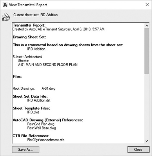
Figure 17-42 The sample transmittal report
Configuring the Transmittal
A transmittal setup contains all the settings for the transmittal, including which files to include, how the files are organized, and how xrefs are included with the drawing. Multiple transmittal setups can be created and saved. This allows you to create different setups for different clients or needs. When you choose the Transmittal Setups… button, AutoCAD displays the Transmittal Setups dialog box (see Figure 17-43). This allows you to modify, rename, or delete an existing setup or create a new transmittal setup. Transmittal setups are similar to page setups or dimension styles in that they simply assign a name to a collection of settings.
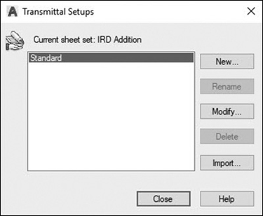
Figure 17-43 The Transmittal Setups dialog box
To create a new setup, choose the New… button in the Transmittal Setups dialog box. This displays the New Transmittal Setup dialog box (see Figure 17-44), where you can assign a name to your new transmittal setup. Each new transmittal setup is created from an existing setup. The Based on: list allows you to choose which setup to use as a basis for your new setup.

Figure 17-44 The New Transmittal Setup dialog box
Once you create a new setup or choose the Modify… button, AutoCAD will display the Modify Transmittal Setup dialog box (see Figure 17-45). This dialog box allows you to modify the settings for the transmittal.
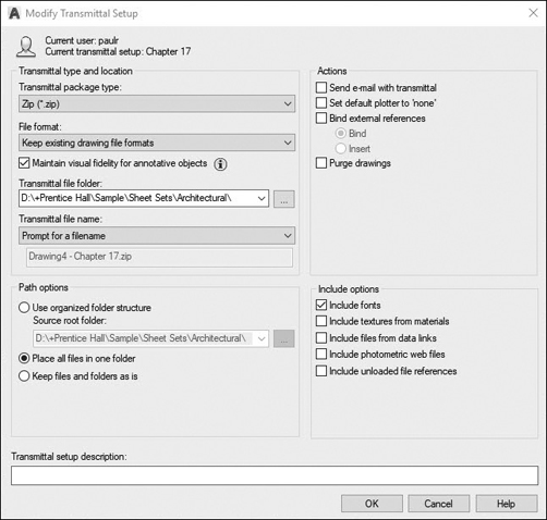
Figure 17-45 The Modify Transmittal Setup dialog box
Transmittal Settings. The Transmittal package type: allows you to select how the files will be stored. The options are described in the following table:
Folder (Set of Files) |
Packages the files in a single file folder. The Transmittal file folder: setting specifies the location of the folder. You may want to create a new folder to store the transmittal files. |
Self-extracting Executable (.exe) |
Packages the files in a self-extracting file. This is similar to a ZIP file but does not require a separate ZIP program to open the files. The user can simply double-click on the files to open, decompress, and extract them. |
ZIP (*.zip) |
Packages the files in a compressed ZIP file. All files are compressed into a single file, which makes them easy to send electronically. |
The File format: option lets you convert AutoCAD 2020 drawings back to AutoCAD 2018 and 2018 LT, AutoCAD 2013 and 2013 LT, AutoCAD 2010 and 2010 LT, AutoCAD 2007 and 2007 LT, AutoCAD 2004 and 2004 LT, or AutoCAD 2000 and 2000 LT release formats. All drawing files and xrefs are converted back to the selected file format prior to packaging them.
The Transmittal file folder: is the location for the transmitted files. The drop-down list will display the nine previous locations that have been used, or you can choose the Browse button to specify a new location.
The Transmittal file name: determines the ZIP or EXE file name and tells AutoCAD which method is used for naming. By default, AutoCAD combines the drawing file name with the transmittal setup name. For example, a drawing called Plan.dwg using the Standard transmittal setup with the Zip package option would have a transmittal file name called Plan-Standard.zip. You can change the default file name by typing a new name in the space below the Transmittal file name:. This option is disabled if the Folder package type is used. These options are described in the following table:
Prompt for a filename |
This method will prompt you for a file name each time you create a transmittal. The file will be stored in the folder set in the Transmittal file folder: setting. |
Overwrite if necessary |
This option will automatically name the file. If that file already exists, AutoCAD will automatically overwrite the existing file. |
Increment file name if necessary |
This option will automatically name the file. If the file already exists, AutoCAD will create a new file name by adding a number to the end of the file name. For example, a ZIP file called Plan-Standard.zip would be incremented to Plan-Standard 1.zip. |
The Path options area allows you to choose how the files are organized within the package. These are described in the following table:
Use organized folder structure |
This method duplicates the folder structure for the files being transmitted. The root folder is the top-level folder for the transmittal. For files that lie within the root folder path, a folder is created for each file’s parent folder. Files that are outside the root folder path are placed in the root folder. Other folders are created as needed for fonts and plot configurations. |
Place all files in one folder |
This option places all files in a single folder defined in the Transmittal file folder option. No subfolders are created. |
Keep files and folders as is |
This option replicates the existing folder structure of all the files included in the transmittal. This option works well when you have xrefs or images stored with full paths because it retains the complete folder structure for all files. |
The Send e-mail with transmittal option will cause AutoCAD to start a new email message with the transmittal files included as attachments.
The Set default plotter to ‘none’ option changes the default plotter for all model and paper space layouts to None. This prevents AutoCAD from trying to communicate with plotters that may not be configured on another user’s system.
The Bind external references option causes AutoCAD to bind all xrefs in the transmittal drawing file. This means that no xref files are included with the transmittal and that all xrefs are automatically bound before packaging. This does not affect the source drawing file, only the transmittal copy. The advantage of using this option is that the person receiving the transmittal will not have to deal with xref paths or missing files. The disadvantage is that for large or complex drawings, binding xrefs may cause the file size to increase significantly.
The Purge drawings option will do a complete purge of all the drawings in the transmittal package.
The Remove Design Feed option removes association to any design feed information for the specified drawings. It is strongly recommended that you do not make or distribute copies of drawings that include embedded design feed IDs.
The Include options area allows you to specify whether to include associated fonts, textures from materials, external files referenced by a data link, photometric web files that are associated with web lights, and unloaded file references.
Exercise 17-8 Transmitting Xrefs
![]() Continue from Exercise 17-7.
Continue from Exercise 17-7.
![]() Start the ETRANSMIT command. If you have any unsaved changes, AutoCAD will ask whether you want to save them. Choose OK to save any changes.
Start the ETRANSMIT command. If you have any unsaved changes, AutoCAD will ask whether you want to save them. Choose OK to save any changes.
![]() Look at the Files Tree and Files Table tabs to see which files are going to be included in the transmittal.
Look at the Files Tree and Files Table tabs to see which files are going to be included in the transmittal.
![]() Choose the Transmittal Setups… button and choose New… to create a new transmittal setup. Name the transmittal setup Chapter 17 and choose Continue to continue setting up the transmittal.
Choose the Transmittal Setups… button and choose New… to create a new transmittal setup. Name the transmittal setup Chapter 17 and choose Continue to continue setting up the transmittal.
![]() Set the Transmittal package type: to Zip and Keep existing drawing file formats. Select a location from the Transmittal file folder: and choose Prompt for a filename.
Set the Transmittal package type: to Zip and Keep existing drawing file formats. Select a location from the Transmittal file folder: and choose Prompt for a filename.
![]() Choose Place all files in one folder and Include fonts. Turn all other options off. Choose OK to save the transmittal setup and Close to return to the Create Transmittal dialog box. Your settings should be set to match Figure 17-46.
Choose Place all files in one folder and Include fonts. Turn all other options off. Choose OK to save the transmittal setup and Close to return to the Create Transmittal dialog box. Your settings should be set to match Figure 17-46.
Figure 17-46 Transmittal settings
![]() Choose OK to create the transmittal. Save the transmittal as CH17_EXERCISE8.
Choose OK to create the transmittal. Save the transmittal as CH17_EXERCISE8.
Chapter Summary
Referencing external drawings is a key feature in environments in which multiple people are working on a project and coordination is crucial. In fact, there is really no other easy way for more than one person to access a drawing file at the same time and maintain data integrity. Sooner or later someone is going to overwrite another person’s changes. That is why if you try to open a drawing that someone else already has open, AutoCAD will only let you open it in read-only mode.
Using external references, you split up a drawing into logical chunks (files) so everyone can work on his or her own stuff and then reference them back together so everyone can coordinate his or her work with that of the others. Obviously, file and document management is critical, hence the importance of how you set up and manage xref paths in your drawings. The editing and update process is also of primary concern. People need the ability to always see the latest information when changes are made, and access needs to be controlled. The good thing is that AutoCAD notifies when changes are made to xrefs in your drawing so that they can be reloaded with the latest information.
This ability to always have the latest information applies to the other types of files that can be referenced in AutoCAD, too. Raster image references allow you to place photos and other images in your drawings while maintaining a link back to the original. The ability to reference DWF, DGN, PDF, point cloud, and coordination model files allows you to share and coordinate your drawing information with many different sources that might not have AutoCAD. Context tabs of the ribbon that display whenever you select one of the different reference types allow you to easily control the appearance and behavior of reference files in your drawings.
When you need to send a drawing that has one or more references to someone else, the AutoCAD eTransmit utility allows you to automatically gather up all of the referenced files and package them together in one ZIP file for easy transfer. It even has the ability to automatically create an email and attach the ZIP file in one step. Alternatively, you can also bind referenced files so that they become part of the original drawing and all reference links are broken. This is typically done as a last resort because you lose all the benefits of using xrefs in the first place.
Chapter Test Questions
Multiple Choice
Circle the correct answer.
1. Which of the following statements best defines an xref?
a. A drawing that is independent of all other drawings
b. A drawing attached to the current or host drawing with a link back to the original drawing
c. A drawing that can bind only to the current drawing
d. All of the above
2. Why would “Reload” be needed when using xrefs?
a. To lock changes out of the current drawing
b. To check updates to a current attached drawing
c. To bind changes to a current drawing
d. All of the above
3. Binding an attached xref drawing will:
a. Isolate the drawing from any more updates
b. Make the attached drawing more editable
c. Bind it somewhat permanently to the current drawing
d. All of the above
4. Which bind-type option will bind named xref objects such as layers, linetypes, and text styles and not rename them with the xref name and a “$0$” prefix?
a. Bind option
b. Insert option
c. Setting BINDTYPE system variable to 0
d. None of the above
5. The XOPEN command is used for:
a. Opening a deleted drawing
b. Opening a new drawing
c. Directly opening an attached xref
d. All of the above
6. The XBIND command is used for:
a. Adding or removing individual dependent definitions from the xrefed drawing to the host drawing
b. Managing xref layer settings
c. Adding or removing layer definitions to the current host drawing
d. All of the above
7. An eTransmit report contains the following information:
a. Date and drawing name
b. File paths and xref file paths
c. Any excluded files
d. All of the above
8. eTransmit files can be which of the following?
a. .exe (self-extracting executable files)
b. .zip (ZIP files)
c. Folder (set of files)
d. All of the above
9. Why would “demand loading” be applied to xrefs?
a. To automatically load your drawing when AutoCAD is opened
b. To speed up AutoCAD and make it run more efficiently
c. To block others from using your xrefs
d. All of the above
10. Why would raster images be applied to a drawing?
a. To provide a company logo background image
b. To provide location points for satellite topographical drawings
c. To trace shapes or profiles
d. All of the above
Matching
Write the letter of the correct answer on the line.
a. External Reference_______ |
1. Displays the Select Image File dialog box |
b. ETRANSMIT_______ |
2. Bypasses the External References palette and directly attaches an xref |
c. IMAGEATTACH_______ |
3. A reference to a drawing file that retains a link back to the original drawing file |
d. XCLIP_______ |
4. Opens an attached xref directly in your current drawing |
e. REFEDIT_______ |
5. Packages drawing and dependent files for file transfer |
f. XATTACH_______ |
6. Binds individual named object definitions from an xref drawing |
g. XBIND_______ |
7. Toggles an image between draft and high-quality mode |
h. IMAGEADJUST_______ |
8. Opens a referenced drawing in a new drawing window |
i. XOPEN_______ |
9. Sets contrast, brightness, and fade on an attached image |
j. IMAGEQUALITY_______ |
10. Crops an external reference to a defined boundary |
True or False
Circle the correct answer.
1.True or False: Changes to “attached” drawings are not shown on the host drawing.
2.True or False: Changes to “bound” drawings are not shown on the host drawing.
3.True or False: “Detach” removes an xref attached drawing.
4.True or False: “Reloading” an xref is done to remove any changes made to the attached drawing.
5.True or False: Layers can be included in attached drawings.
6.True or False: When binding an xref, named objects such as layers, linetypes, and textstyles are always renamed by prefixing the named object with the xref file name followed by “$0$”.
7.True or False: eTransmit can also provide a report and other files along with the drawing file to be transmitted.
8.True or False: With demand loading, “Enabled with Copy” lets others use your drawing while you continue to edit it.
9.True or False: The resolution can be adjusted on an attached image on your AutoCAD drawing.
10.True or False: Image quality cannot be adjusted on an attached image on your AutoCAD drawing.
Chapter Projects
 Project 17-1: Classroom Plan, continued from Chapter 16 [BASIC]
Open drawing P16-1 from Chapter 16.
Switch to the Architectural Title Block layout, and erase the existing title block information.
Attach the drawing Architectural D-Size.dwg created in Chapter 16 as an overlay xref. Place the xref at the coordinates −.75,−.5.
Insert the drawing Title Attributes Architectural D-Size.dwg as a block. Use an insertion point of −.5,.25. Fill in appropriate values for the attributes. Your drawing should resemble Figure 17-47.

Figure 17-47
Save your drawing as P17-1.
 Project 17-2: Logo/B-Size Mechanical Border, continued from Chapters 10 & 16 [INTERMEDIATE]
Open drawing P10-2. Move the geometry so the lower left corner of the logo is located at 0,0.
Create a new text style called PEARSON using the Arial.ttf font. Assign a width of 1.25 to the style.
Create a second text style called PH using the Times New Roman.ttf font.
Add the text shown in Figure 17-48. All text is 0.375 high. Assign the color 255 directly to the text.

Figure 17-48
Hint: Use the DRAWORDER command to send the fill areas behind.
Scale the logo so the height is .375, as shown in Figure 17-48.
Save the drawing as PH-Logo.
Open the template file Mechanical B-Size.DWT from Project 16-2 in Chapter 16.
Set the Mechanical B-Size layout current and attach the drawing PH-Logo as an overlay reference. Place the drawing as shown in Figure 17-49.

Figure 17-49
Save the drawing template as Mechanical B-Size.DWG.
 Project 17-3: Architectural D-Size Border, continued from Chapter 16 [ADVANCED]
Start a new drawing using the acad.dwt template.
Create the architect’s professional seal shown in Figure 17-50 as follows:

Figure 17-50
Draw all information on Layer 0.
Use the DONUT command to create a donut at 0,0 with an inside diameter of 1.70″ and an outside diameter of 1.75″.
Use the CIRCLE command to create the inside circle with a diameter of 1.25″.
Use the TEXT command to create all text as single-line text. Outside curved text is 0.125″ high. Inside text is 0.093″.
Save the drawing as Seal.DWG.
Open the template file Architectural D-Size.DWT from Project 16-3 in Chapter 16.
Attach the architect’s professional seal drawing created above (Seal.DWG) as an external reference at the center of the title border circle as shown in Figure 17-50 so that it is rotated 90°.
Save the template as Architectural D-Size.DWG.
Project 17-4: Optical Mount—English Units, continued from Chapter 15 [INTERMEDIATE]
Open drawing P15-4 from Chapter 15.
Switch to the Mechanical B-Size layout. Erase the existing title block geometry, leaving only the viewport.
Attach the drawing Mechanical B-Size.DWG as an overlay xref. Place the reference at 0,0 at a scale of 1 and a rotation angle of 0.
Insert the drawing Title Attributes Mechanical B-Size.dwg as a block. Place the block at 0,0 at a scale of 1 and a rotation angle of 0. Enter appropriate values for the title block attributes. Your drawing should look like Figure 17-51.

Figure 17-51
Save the drawing as P17-4.
Project 17-5: Residential Architectural Plan, continued from Chapter 15 [ADVANCED]
Open drawing P15-5 from Chapter 15.
Switch to the Architectural D-Size layout. Erase the existing title block geometry, leaving only the viewport.
Attach the drawing Architectural D-Size.DWG as an overlay xref. Place the reference at 0,0 at a scale of 1 and a rotation angle of 0.
Insert the drawing Title Attributes D-Size.dwg as a block. Place the block at 0,0 at a scale of 1 and a rotation angle of 0. Enter appropriate values for the title block attributes. Your drawing should look like Figure 17-52.
Save the drawing as P17-5.
Figure 17-52