Chapter Eleven: Adding Text
Chapter Objectives
Control the appearance of text using text styles and fonts
Understand the difference between TrueType fonts and AutoCAD SHX fonts
Create and edit multiline text
Create and automate horizontal, diagonal, and tolerance type stacked text
Create and edit single-line text
Insert intelligent text fields
Find and replace text in a drawing
Check text spelling for a whole drawing
Introduction
They say a picture is worth a thousand words, and while the lines, arcs, and circles on a drawing can convey a great deal of design information, at the end of the day you will need to annotate your drawings in order to completely communicate your design.
annotate: To add text, notes, and dimensions to a drawing.
Text on a drawing comes in many different shapes, sizes, and forms. It is used in a drawing’s title block to tell the reader who created the drawing and when. Title block text might also provide information about who checked the drawing or what revision of a design you are viewing—both very important pieces of information. Of course, there is also the text that is created directly on a drawing in the form of notes, labels, and callouts with specific design instructions, references to other drawings, part numbers, and specifications, to name but a few. Figure 11-1 shows a few examples of different types of drawing annotation.

Figure 11-1 Examples of drawing annotation
Manually annotating a drawing on the drafting board, originally referred to as lettering, was a tedious and time-consuming task. In fact, some considered it an art form because of the skill and dexterity needed to annotate a drawing properly.
Those days are long gone. AutoCAD provides a number of tools that allow you to annotate your drawings, in a fashion that meets or exceeds industry drafting standards quickly, and with minimum effort. You can add multiple lines of text by simply defining a boundary area that the text should fill so that, as you type, AutoCAD automatically formats the text to fit. It is also possible to add text, known as a field, which can automatically update itself with the current date, the name of the drawing file, or the properties of an object in a drawing!
In this chapter, we look at the tools AutoCAD provides for annotating your drawing. We also examine the tools used to edit annotation features. Once again, AutoCAD makes it quick and easy to change information once it is created in a drawing so that updating text is as simple as double-clicking with your mouse.
Tip
Text and other annotation features should be placed on a unique layer so that you can control their visibility. Text can be one of the most resource-intensive objects in a drawing. A drawing with a lot of text can become significantly bogged down. Being able to freeze text on its layer can significantly increase drawing performance.
Controlling the Appearance of Text
The appearance of text on a drawing is very important. Text should be created as legibly as possible so that it can be easily read and understood with minimum effort. Because of this, different standards have been established to control everything from the text font and height to how text should be located and oriented in a drawing.
Fonts
These days most people are familiar with text fonts. The font is what determines how text looks by defining its typeface.
typeface: The style or design of a font.
Some of the more popular TrueType fonts are shown in Figure 11-2.

Figure 11-2 Examples of TrueType fonts
Tip
A drawing named TrueType.DWG, located in the AutoCAD Sample folder, shows the character map for many of the TrueType fonts.
TrueType Fonts Versus AutoCAD Fonts. The fonts shown in Figure 11-2 are known as TrueType fonts. TrueType fonts are the standard font type provided as part of Microsoft Windows. TrueType is actually a specification developed by Apple Computer and later adopted by Microsoft that allows for scalable text, meaning the same font can be displayed at any size and resolution. A TrueType font typically has a three-letter TTF filename extension.
Note
The TEXTFILL system variable controls the filling of TrueType fonts while plotting and rendering. Setting TEXTFILL = 0 turns the solid fill off. Setting TEXTFILL = 1 turns the solid fill on.
In addition to TrueType fonts, AutoCAD comes with its own set of fonts referred to as SHX fonts because of their three-letter SHX filename extension. Some of the standard AutoCAD SHX fonts are shown in Figure 11-3.
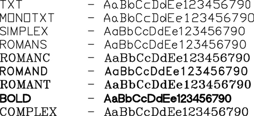
Figure 11-3 Examples of AutoCAD fonts
As you can see from Figure 11-3, the AutoCAD fonts range from simple to complex. The most basic AutoCAD font is TXT.SHX. Text can be one of the most demanding factors on your computer system resources. Text with a complex font consumes more memory than text with a simple font. If you have a drawing with a lot of text, a complex double- or triple-line font takes much longer to regenerate than a simple font such as TXT.SHX.
Tip
A good balance of performance versus legibility is provided by both the ROMANS.SHX and SIMPLEX.SHX AutoCAD fonts.
Fonts are typically assigned to text styles because this provides the most control over the appearance of text in your drawing. It is possible to assign fonts directly to text objects using multiline text, but this approach is typically avoided because of the increased management needs. Text styles and multiline text are both discussed later in this chapter.
Tip
The FONTALT system variable specifies an alternate font to be used when a particular font file cannot be located on your system. By default, the FONTALT system variable is set to the AutoCAD SIMPLEX.SHX font.
Text Height
The height of text in a drawing is very important and, as mentioned earlier, is also determined by industry drafting standards. Text that is used for notes on a drawing is typically 0.100″ to 0.125″ (2 mm to 3 mm) tall, whereas text for titles is typically 0.188″ to 0.25″ (5 mm to 6 mm) tall. These are the standard heights that text should be on the final plotted or printed drawing, but they are not always the heights used when text is added to a drawing. Remember from Chapter 1 that if the final printed drawing is not at a scale of 1:1, you must scale annotation features up or down so that they plot at the correct size. This is accomplished by multiplying the desired printed text height by the reciprocal of the plot or viewport scale. This multiplier is referred to as the drawing scale factor.
Tip
The TEXTSIZE system variable controls the default text height used in a drawing. It is set to 0.20 by default.
Annotation Scale
Instead of calculating the scale factor manually as just described, it is possible to automate the process of scaling text so that it is created at the correct height for the final plotted drawing scale using the AutoCAD Annotation Scale feature located on the right side of the status bar.
Note
Remember that even though text with multiple annotation scales can be viewed at multiple scales, it is in reality represented by only one text object. AutoCAD does not make multiple copies for each scale representation. In fact, the Annotation Scale feature was developed to eliminate the need to create new text for each scale and to have to rely on layers to turn different scales off and on.
When text with its annotative property enabled is added to the drawing, it automatically scales up or down by the current annotation scale so that it is the correct height.
Taking it a step further, it is even possible to add additional different annotation scales to text automatically so that it can be viewed at different heights for different scale factors. Using this feature, each time the annotation scale is changed, all the text that has its annotative property enabled is resized accordingly.
The best way to take advantage of the Annotation Scale feature when you are working with text is to enable the Annotative check box in the current text style. Text styles are explained in detail in the next section.
Text Styles
The font, height, and other characteristics that affect the appearance of text are typically managed using text styles. All text in a drawing has a text style associated with it. When you add text to a drawing, it is created using the current text style settings. The current text style can be set by selecting it from the text style list on the expanded Annotation panel on the Home tab of the ribbon or the Text panel on the Annotate tab of the ribbon shown in Figure 11-4, selecting it from the text style list in the multiline text editor explained later, or typed in if you are creating single-line text.
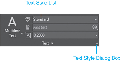
Figure 11-4 Text panel on the Annotate tab of the ribbon
The default text style is named STANDARD, which is assigned the Arial TrueType font with a text height of 0.0000″.
Tip
The Annotate tab of the ribbon provides quick and easy access to the most commonly used annotation tools. For this reason, you should select the Annotate tab to display the Annotate tools whenever you are adding text.
It is possible to modify the STANDARD text style or create one or more new text styles with user-defined names that can have different fonts, heights, or other properties.
Different text styles should be used to manage the different text types in a drawing. You might create a font named NOTES that is assigned the SIMPLEX.SHX font with a height set to 0.125″ that can be used for all note-type text in a drawing. You can then create another style named TITLES that is assigned the bold Arial TrueType font and a height of 0.25″ that can be used for all the title-type text in a drawing. See Figure 11-5.

Figure 11-5 Examples of different text styles
Note
Text height either can be controlled by the text style height setting, or it can be specified when the text is created. If the text height is set to 0.000″ in the text style, you must specify the text height when text is added to a drawing. If the text style height is set to any value greater than 0.000″, the text height is set automatically when text is added to a drawing.
Using text styles to control the appearance of the different text types in a drawing provides a number of advantages. First, text styles make it easier to change the appearance of text if required. For instance, if the font specification changes for a certain type of text, you need to update only the corresponding text style. Otherwise, you must find every instance of text in a drawing that uses the old font and change it manually.
Using text styles to control the appearance of text also helps promote the use of drafting standards by providing the ability to have text look consistent for an entire project or organization.
Note
Text style names can be up to 255 characters long and can consist of letters, numbers, and a few other special characters such as underscores, hyphens, and even spaces. The default style name created by AutoCAD is “Style” followed by an integer value (i.e., Style1, Style2).
Tip
Use AutoCAD template files to your advantage by creating all your standard default text styles in a template file that can be used when you start a new drawing. You can also use DesignCenter to copy text styles from another drawing using drag-and-drop techniques.
The Text Style Dialog Box
The Text Style dialog box allows you to control and manage text styles in a drawing by allowing you to do the following:
Set a text style current
Add or delete a text style
Rename a text style
Assign or change the text style font
Set the text height
Apply different text effects that make text read upside down, backward, or even vertically
Change the text width so it is wider or narrower
Slant text at a specified angle so it leans forward or backward
The Text Style dialog box can be displayed by selecting the Text Style button on the Text panel shown in Figure 11-4, by selecting Text Style… from the Format menu, or by typing STYLE or ST.
Text Style |
|
|---|---|
Ribbon & Panel: |
Annotate | Text |
Menu: |
Format | Text Style… |
Command Line: |
STYLE |
Command Alias: |
ST |
The Text Style dialog box is shown in Figure 11-6. The following sections explain the different text style settings and features.
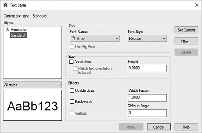
Figure 11-6 The Text Style dialog box
Styles List. Styles: is where you can select a text style to be current, rename a text style, or delete an existing text style. The text style list contains all the text styles in the drawing and displays the current text style. To change the current style, you can double-click on it, right-click and select Set Current, or select the Set Current button.
Note
Only unreferenced text styles can be deleted. There can be no text in the drawing that uses the text style you wish to delete. In fact, the Delete button is disabled if the selected text style is referenced anywhere in the drawing.
To create a new text style, select the New… button.
The New… button displays the New Text Style dialog box shown in Figure 11-7.
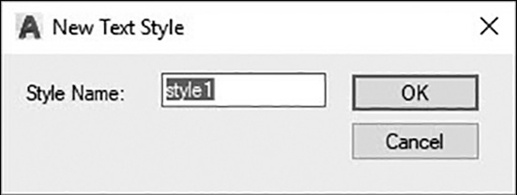
Figure 11-7 The New Text Style dialog box
The default style name is “Style” followed by a sequenced number (i.e., Style1, Style2, Style3). Typically you want to supply your own style name. One common approach is to name the style the same name as its associated font. For instance, if you are going to assign the SIMPLEX.SHX font, you would name the text style “Simplex.” This way when you go to make a text style current, you can immediately tell what font will be used based on its name.
The Delete button on the Text Style dialog box deletes the selected text style.
Font Area. The Font area of the Text Style dialog box allows you to change the style’s font name and style.
The Font Name: drop-down list contains a list of all the registered TrueType fonts and the AutoCAD SHX compiled shape fonts. The TrueType fonts are preceded with the “TT” icon, and the AutoCAD fonts are preceded with an icon that looks like a compass.
The Font Style: list box specifies font character formatting such as italic, bold, or regular for TrueType fonts. The Font Style: list is disabled when an AutoCAD SHX type font is selected. When the Use Big Font check box is selected, this option changes to Big Font Name and is used to select a Big Font file name.
Note
Changing a text style’s font will automatically update all the text in the drawing that uses the selected text style with the new font. In fact, that is a good reason to use text styles to manage your fonts—you have centralized control over the text appearance.
The Use Big Font check box is used to specify an Asian-language Big Font file. Big Font files provide an extended character set needed for many Asian languages with large alphabets. The Use Big Font check box is enabled only when an AutoCAD SHX font file is selected. TrueType fonts do not have this capability.
Tip
It is possible to define several text styles that use the same font.
Size Area. The Size area of the Text Style dialog box allows you to control the height of text based on the text style.
The Height text box is where you enter the desired text height for all the text created using the selected text style. Remember earlier it was explained that if you use the default height of 0.000″, AutoCAD requires you to specify a text height each time you add text and the selected text style is current. Specifying a height greater than 0.00″ sets the text height for this style so that you do not need to specify a height every time you add text. Some TrueType fonts may be displayed at a smaller height than AutoCAD SHX fonts with the same height setting.
Note
Unlike changing the font, changing the height does not affect any existing text in the drawing that was created using the selected style. The new text height will be used by any new text that is created. Changing the height of existing text is discussed later in this chapter.
Selecting the Annotative check box enables the automated Annotation Scale feature discussed earlier for all text that is created using the current text style. When the Annotative check box is selected, the Height text box is relabeled the Paper Text Height text box, and the Match text orientation to layout check box is enabled.
The Paper Text Height text box reflects what you want the final plotted text height to be. AutoCAD, in turn, will automatically scale the annotative text up or down to match this height based on the current annotation scale.
Selecting the Match text orientation to layout check box automatically sets the orientation of the text in paper space viewports to match the orientation of the current layout.
Tip
It is another common convention to name a text style to reflect the text height if it is set to anything other than 0.00″. For instance, a text style assigned the SIMPLEX.SHX font and a height set to 0.125″ might be named Romans .125 or Romans_125. This way you know the font and the height when you set a text style current.
Effects Area. The Effects area of the Text Style dialog box allows you to apply different font effects such as whether text is displayed upside down, backward, or stacked vertically. You can also change the text width factor so that text can be made wider or narrower, as well as set at an oblique angle that will slant the text forward or backward at the specified angle—a technique that can be used to create italicized text.
The Upside down setting displays text upside down when it is selected. The Backwards setting displays text backward. The Vertical setting displays text stacked vertically. See Figure 11-8. The Vertical setting is available only if the selected font supports dual orientation.
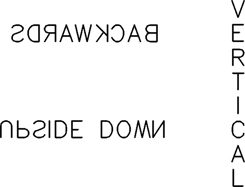
Figure 11-8 The Backwards, Upside down, and Vertical effects
Note
The Upside down setting affects single-line text only. New and existing multiline text is not affected by the Upside down setting.
The Backwards setting affects single-line text only. New and existing multiline text is not affected by the Backwards setting.
The Width Factor: setting controls horizontal text spacing. The default width is 1.0. Specifying a value greater than 1.0 expands the text so that it is wider. Specifying a value less than 1.0 condenses the text so it is narrower. See Figure 11-9.
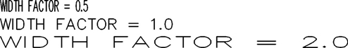
Figure 11-9 Examples of Width Factor effects
The Oblique Angle: setting controls the oblique angle, or slant, of the text. The angle entered is measured from 90° vertical so that a positive angle slants text forward and a negative angle slants text backward. It is possible to enter a value between −85° and 85°. See Figure 11-10.
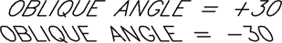
Figure 11-10 Examples of Oblique Angle effects
Applying Changes to a Text Style. The Apply button applies any changes made in the Text Style dialog box to any text in the drawing that uses the selected style.
The Cancel button will discard any changes and exit the Text Style dialog box. The Cancel button changes to a Close button whenever you click on the Apply button. Creating, renaming, or deleting a text style are all actions that cannot be canceled.
Note
The Vertical setting affects only text styles that are assigned an SHX type font. TrueType fonts cannot be displayed vertically.
Some TrueType fonts using the effects described in this section might appear bold in your drawing. Don’t be too concerned because their appearance has no effect on the plotted output.
Exercise 11-1 Creating and Modifying Text Styles
![]() Start a new drawing using the acad.dwt drawing template.
Start a new drawing using the acad.dwt drawing template.
![]() Update the STANDARD text style so that its font is set to the SIMPLEX.SHX AutoCAD font.
Update the STANDARD text style so that its font is set to the SIMPLEX.SHX AutoCAD font.
![]() Create a text style named NOTES with the following settings:
Create a text style named NOTES with the following settings:
a. Font = Simplex.shx
b. Height = 0.125″
![]() Create a text style named TITLES with the following settings:
Create a text style named TITLES with the following settings:
a. Font = Arial
b. Height = 0.25″
![]() Create a text style named ARCHITECTURAL with the following settings:
Create a text style named ARCHITECTURAL with the following settings:
a. Font = CityBlueprint
b. Height = 0.125″
![]() Create a text style named MECHANICAL with the following settings:
Create a text style named MECHANICAL with the following settings:
a. Font = GDT.shx
b. Height = 0.100″
![]() Save the drawing as CH11_EXERCISE 1.
Save the drawing as CH11_EXERCISE 1.
Creating Multiline Text
Multiline text is a complex text object that can consist of multiple lines of text that you enter in paragraph form using an in-place text editor that resembles a simple word processing program. The text is automatically formatted to fit a rectangular boundary area that you define using two corner points before the text editor is displayed. AutoCAD automatically determines the horizontal length of the line of text by inserting soft returns similar to a word processor. The vertical height of the multiline text object depends on the amount of text, not the vertical height of the bounding box. See Figure 11-11.
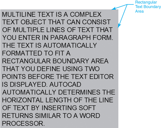
Figure 11-11 Multiline text
Multiline Text |
|
|---|---|
Ribbon & Panel: |
Home | Annotation |
Menu: |
Draw | Text| Multiline Text… |
Command Line: |
MTEXT |
Command Alias: |
T or MT |
The in-place text editor creates and edits the text in its current location and is transparent so you can see the drawing line work below to locate text accordingly. Some of the features and benefits of multiline text include:
Setting tabs and indents
Automated field insertion
Importing external text files in ASCII or RTF format
Enhanced symbol and special character insertion
Bulleted and numbered list creation
Creating stacked fractions and geometric tolerances
Resizing the text boundary area using grips, and reformatting the text line length automatically
The ability to switch selected text between uppercase and lowercase with the click of a mouse
The ability to create multiple columns of text
The MTEXT command is used to create multiline text using the in-place text editor. Editing multiline text using the in-place editor is explained later in this chapter.
When you start the MTEXT command, AutoCAD displays the current text style and height at the command line as follows:
Current text style: "Standard" Text height: 0.2000
AutoCAD prompts you to Specify first corner: and the text “abc” is displayed on the cursor crosshairs as shown in Figure 11-12.
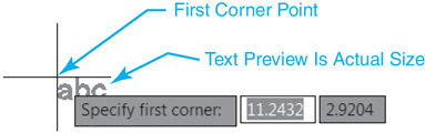
Figure 11-12 First corner of the multiline text boundary area
Because the size of the text is the actual size that the text will be created based on the current text height setting, it is affected by zooming in on and out of your drawing. Select the first corner of the rectangular area that you want to use to create the text. AutoCAD prompts you to Specify opposite corner or ![]() and displays a preview of the rectangular area as shown in Figure 11-13.
and displays a preview of the rectangular area as shown in Figure 11-13.

Figure 11-13 Second corner of the multiline text boundary area
The arrow at the bottom of the rectangle indicates that the text flow is top to bottom. This is because the default justification for multiline text is the top-left corner. It is possible to change the justification by selecting the Justify option when AutoCAD prompts you to Specify opposite corner or ![]() . The different multiline justification options are shown in Figure 11-14.
. The different multiline justification options are shown in Figure 11-14.

Figure 11-14 Multiline text justification options
Note
It is also possible to change the justification after you enter the in-place text editor using the Text Editor context tab of the ribbon explained later.
Notice how the arrows change to indicate how the justification affects the text flow.
The other options that are available before you select the second text boundary corner point are as follows:
Height
Justify
Line spacing
Rotation
Style
Width
Columns
Most options can also be set in the in-place text editor after selecting the second corner point, whereas the rotation angle must be indicated before selecting the second corner point.
The Rotation option allows you to specify the angle for the complete multiline text object so that the whole paragraph of text is rotated at the angle you specify.
Once all the desired multiline options are set, select the second point to define the initial text boundary area. After you select the second point, AutoCAD displays the in-place multiline text editor shown in Figure 11-15 so you can start entering text. At the same time, the current tab of the ribbon at the top of the AutoCAD window switches to the Text Editor context tab of the ribbon shown in Figure 11-15 so you can access the multiline text tools and formatting options.
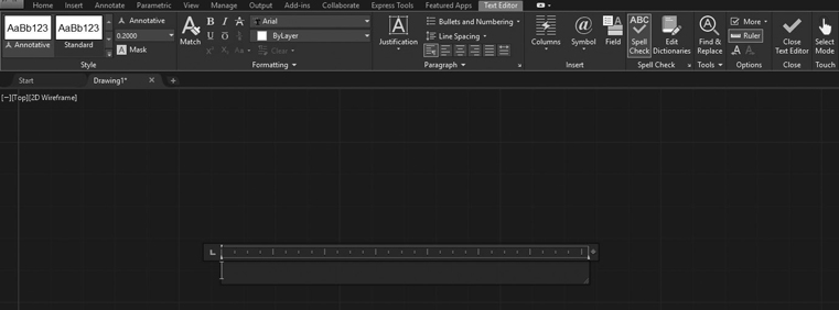
Figure 11-15 The in-place multiline text editor
The In-Place Multiline Text Editor
The in-place multiline text editor consists of the following components and features:
In-place text editor window
Ruler
Text Editor context tab of the ribbon
Right-click shortcut menu
The in-place text editor window is where you enter the text. As mentioned, it works like most text editors and word processor software. As you type and the text reaches the end of the text editor window, AutoCAD automatically enters what is commonly referred to as a “soft” return to break the line. You can also enter your own “hard” returns if you wish by pressing the <Enter> key. All the other common text editor keyboard controls are available to help you navigate, select, copy, paste, delete, and edit text as you type.
Tip
You can use the Windows Clipboard to copy and paste text between other Windows applications and AutoCAD.
Multiline Text Editor Keyboard Controls |
|
|---|---|
Key or Key Combination |
Description |
Home |
Moves cursor to the beginning of the current line |
End |
Moves cursor to the end of the current line |
<Ctrl>+Home |
Moves cursor to the first column of the first line |
<Ctrl>+End |
Moves cursor to the end of the last line |
<Del> |
Deletes character to the right of cursor |
<Ctrl>+<Del> |
Deletes complete word to the right of cursor |
Page Up |
Moves cursor to beginning of paragraph |
Page Down |
Moves cursor to end of paragraph |
Arrow Keys |
Moves cursor one position the direction of the arrow |
<Shift>+ Arrow Keys |
Selects and highlights text under cursor as it moves |
Backspace |
Deletes character to the left of cursor |
<Ctrl>+Backspace |
Deletes word to the left of cursor |
<Ctrl>+<Shift>+Space |
Inserts a nonbreaking space |
<Ctrl>+A |
Selects all text |
<Ctrl>+C |
Copies selected text to the Windows Clipboard |
<Ctrl>+V |
Pastes text from Windows Clipboard at current cursor position |
<Ctrl>+X |
Cuts selected text so that the text is copied to the Windows Clipboard |
<Ctrl>+Z |
Undoes last operation |
<Ctrl>+<Shift>+U |
Changes selected text to all uppercase |
<Ctrl>+<Shift>+L |
Changes selected text to all lowercase |
When you are finished entering text, you have three ways to exit the multiline text editor and create the text in the drawing:
Select the Close Text Editor button on the Text Editor context tab of the ribbon.
Click anywhere outside the text editor with your mouse.
Hold down the <Ctrl> key and press <Enter>.
To close the text editor without saving the text or any changes, press the <Esc> key.
Exercise 11-2 Creating Multiline Text
![]() Continue from Exercise 11-1.
Continue from Exercise 11-1.
![]() Set the NOTES text style current.
Set the NOTES text style current.
![]() Create the following paragraph of multiline text within an area that is 3″ wide and 3″ tall:
Create the following paragraph of multiline text within an area that is 3″ wide and 3″ tall:
The in-place text editor window is where you enter text. As
mentioned, it works similarly to most text editors and word
processor software you might be familiar with. As you type and the
text reaches the end of the text editor window, AutoCAD
automatically enters what is commonly referred to as a "soft" return
to break the line.
![]() Save the drawing.
Save the drawing.
The Ruler. The ruler indicates the width of the text using the current units setting. The diamond at the right end of the toolbar can be used to adjust the width of the multiline text boundary box by clicking and dragging with your mouse.
The arrow on the top-left side of the ruler can be used to set the indent for the first line of a paragraph by clicking on it and dragging it to the desired position with your mouse as shown in Figure 11-16.
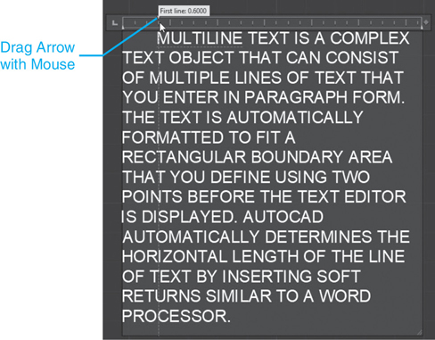
Figure 11-16 Setting the first line paragraph indent distance
The arrow on the bottom-left side of the ruler can be used to set the indent for the whole paragraph by clicking on it and dragging it to the desired position with your mouse as shown in Figure 11-17.

Figure 11-17 Setting the entire paragraph indent distance
You can create one or more tab stops by clicking with your mouse in the ruler where you want to locate the tab stop as shown in Figure 11-18.

Figure 11-18 Setting tab stops
The button on the far left sets the tab type. Clicking on it goes through the left, center, right, and decimal tab types.
Once a tab stop is created, you can move it by placing your cursor over the top of it and dragging it when the cursor changes to a double horizontal arrow. To remove a tab stop, simply click on it with your cursor and drag it off the toolbar.
Note
You can turn the ruler off using the Text Editor context tab of the ribbon explained in the next section. The ruler stays off the next time you use the multiline text editor.
Exercise 11-3 Using Tabs
![]() Continue from Exercise 11-2.
Continue from Exercise 11-2.
![]() Make sure NOTES is the current text style.
Make sure NOTES is the current text style.
![]() Create the following table of multiline text within an area that is 4″ wide and 4″ tall with tab stops at every 1″:
Create the following table of multiline text within an area that is 4″ wide and 4″ tall with tab stops at every 1″:
1    2    3    4
5    6    7    8
9   10   11   12
![]() Save the drawing.
Save the drawing.
The Text Editor Context Tab of the Ribbon
The Text Editor context tab of the ribbon shown in Figure 11-15 is used to control all aspects of the text’s appearance ranging from the text style and font to the text height and justification. The various settings can be applied to new text or existing text that has already been selected (highlighted). The different Text Editor context ribbon panels are explained in the following sections.
Tip
Remember that it is common to control most of the different format settings using text styles as explained earlier in this chapter because it provides central control over the text appearance, making text formatting easier to update. Applying different format options to text directly in the multiline text editor is considered a text style override. Using overrides is typically avoided if possible.
The Style Panel. The Style list specifies the text style to use for new text or changes the text style of any selected text. Text styles and their usage were discussed in detail at the beginning of this chapter.
The Annotative button toggles the text annotative property on and off for automatic text height scaling.
The Text Height list box sets the character height for new text or changes the height of selected text. A multiline text object can contain characters of various heights. If the height you wish to use is not listed, you must click in the Text Height box and type it. It then becomes part of the list so you can select it from the list box the next time.
The Background Mask button displays the Background Mask dialog box shown in Figure 11-19. This dialog box allows you to make the background of the finished multiline text boundary box opaque, as well as set its color. The Use background mask check box turns the background on and off. The Border offset factor: setting allows you to extend the background area beyond the original multiline text boundary area.

Figure 11-19 The Background Mask dialog box
You either can apply a fill color to the background area via the color list in the Fill Color area at the bottom of the dialog box, or you can elect to use the drawing background color by selecting the Use drawing background color check box. Using the drawing background color allows you to block out line work underneath the multiline text boundary box so you can’t see it.
Note
Remember that text styles that have backward or upside-down effects do not work with multiline text and are not displayed.
Tip
If the current text style height is set to 0.0, you can change the default multiline text height displayed in the Text Height list box by setting the TEXTSIZE system variable. The default text height is 0.20.
The Formatting Panel. The Match Properties tool allows you to apply properties between items in a selected text editor. It also works on dimensions, tables, and other Mtext-based drawing objects.
Note
The Match Properties button is “sticky” so you can apply the properties of the selected text multiple times.
The Bold button turns bold formatting on and off for new or selected text. This option is available only for characters using TrueType fonts.
The Italic button turns italic formatting on and off for new or selected text. This option is available only for characters using TrueType fonts.
The Strikethrough button puts a line through selected text.
The Underline button turns underlining on and off for new or selected text.
The Overline button places a line over selected text.
The Stack button allows you to format text representing a fraction or tolerance so that the left character is placed on top of the right character as a horizontal fraction, diagonal fraction, or tolerance. It is thoroughly explained later in the “Stacked Text” section.
The Superscript button converts all selected text to superscript.
The Subscript button converts all selected text to subscript.
The UPPERCASE button converts all selected text to uppercase.
The lowercase button converts all selected text to lowercase.
The Font list specifies the font to use for new text or changes the font of any selected text. Both TrueType and the AutoCAD SHX fonts are listed. It is possible to mix different fonts within the same paragraph of multiline text.
The Color list specifies a color for new text or changes the color of selected text. You can also select one of the colors in the Color list or select the Select Colors option to display the Select Color dialog box.
The Clear menu allows you to remove character, paragraph, or all formatting from the selected text.
Certain features are displayed on the expanded panel. The Oblique Angle box controls the oblique angle, or slant, of new or selected text. The angle entered is measured from 90° vertical so that a positive angle slants text forward and a negative angle slants text backward. It is possible to enter a value between -85° and 85°. You can either type a value in the box or select the up and down arrows on the right to increase or decrease the value by 1. See Figure 11-10 for examples of text that has been obliqued.
The Tracking box decreases or increases the space between characters for new or selected text. You can either type a value in the box or select the up and down arrows on the right to increase or decrease the value by 0.1.
The Width Factor box controls the text character width. The default width is 1.0. Specifying a value greater than 1.0 expands the text so that it is wider. Specifying a value less than 1.0 condenses the text. You can either type a value in the box or select the up and down arrows on the right to increase or decrease the value by 0.1. See Figure 11-9 for examples of Width Factor settings.
The Paragraph Panel. The Justification button displays a menu with the same two-letter multiline text justification options shown earlier in Figure 11-14 (Top Left TL, Middle Left ML, etc.) when using the Justify option when you first start the MTEXT command. The Justification menu allows you to change the text justification within the multiline text editor.
The Bullets and Numbering button displays the menu shown in Figure 11-20 with the three different list formats (Numbered, Lettered, and Bulleted) along with various options:
Off Removes letters, numbers, and bullets from the selected text without changing the indentation
Numbered Creates a numbered list using numbers with periods for each list item
Lettered Allows you to switch between uppercase and lowercase letters with periods for each list item. Double letters are used if the list has more items than the alphabet
Bulleted Creates a bulleted list using round filled circles for each list item
Start Starts a new numbering or lettering sequence
Continue Adds selected text to the list above and continues the numbering or lettering sequence
Allow Auto Bullets and Numbering Toggles the Auto Bullets feature on and off. The Auto Bullets feature creates a list when you enter a letter or number followed by a period “.”, closing parenthesis “)”, greater than symbol “>“, right curly bracket “}”, comma “,”, or square bracket “]”. A lightning bolt icon indicates that automatic bullets or numbering has started. You can click on the lightning bolt icon to access different controls including an option to remove bullets or numbering
Allow Bullets and Lists Disables the Bullets and Numbering feature

Figure 11-20 The Bullets and Lists menu
The Line Spacing button displays a menu that allows you to set the text line spacing for the multiline text object. Line spacing for multiline text is the distance between the bottom of one line of text and the bottom of the next line of text where single spacing is 1.66 times the text height. You can set the spacing increment to a multiple of single-line spacing using the following predefined scale factors:
1.0x Single-line spacing
1.5x One-and-a-half-line spacing
2.0x Double-line spacing
2.5x Two-and-a-half-line spacing
Selecting More… from the Line Spacing menu displays the Paragraph dialog box so you can make additional adjustments. The Paragraph dialog box is explained in detail next.
Selecting the angled down arrow on the far right of the panel title bar displays the Paragraph dialog box shown in Figure 11-21 so that you can do the following:
Add and remove tab stops
Set left and right indents
Set the horizontal paragraph justification
Set the spacing between paragraphs
Set the line spacing for the paragraph
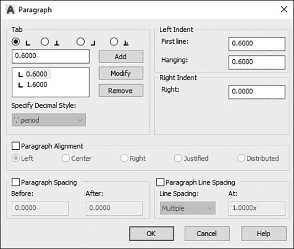
Figure 11-21 The Paragraph dialog box
The Tab area allows you to add and remove left, center, right, and decimal tab stops. To add a tab, enter the tab distance and select the Add button. To delete a tab, select it from the list and select the Remove button.
Note
Different tabs can also be selected from the Tab button on the left side of the ruler and then dragged into position.
The Left Indent area allows you to set the first line and hanging indent distances.
The Right Indent area allows you to set the right-side indent distance.
The Paragraph Alignment area allows you to control the horizontal paragraph justification, text flow, and spacing using one of the following methods:
The Left option aligns text on the left-hand margin so text flows right.
The Center option centers text on the centerline of the text boundary so text flows both directions.
The Right option aligns text on the right-hand margin so text flows left.
The Justified option spreads text out to fill the text boundary width by putting space between words.
The Distributed option spreads text out to fill the text boundary width by putting space between letters.
The Paragraph Spacing area controls the spacing between paragraphs. Selecting the Paragraph Spacing check box enables the Before: and After: text boxes so that it is possible to set different spacing before and after a paragraph.
The Paragraph Line Spacing area controls the multiline line spacing. Line spacing for multiline text is the distance between the bottom of one line of text and the bottom of the next line. The default for single-line spacing is 1.66 times the height of the text. The default spacing is Multiple, which is basically a multiplier that is applied to the preceding formula. The default setting is 1X, or one time. For double-line spacing, you would set Multiple to 2X and so on. The Exactly option maintains a consistent spacing using the absolute distance you specify. Using the Exactly option, it is possible to overlap rows. The At least line spacing option automatically increases line spacing to accommodate characters that are too large to fit.
Select OK in the Paragraph dialog box to exit and save your changes.
The five buttons to the right of the Paragraph button on the Paragraph panel control the horizontal justification and text spacing using the same Paragraph Alignment options provided in the Paragraph dialog box:
The Left button aligns text on the left-hand margin so text flows right.
The Center button centers text on the centerline of the text boundary so text flows both directions.
The Right button aligns text on the right-hand margin so text flows left.
The Justified button spreads text out to fill the text boundary width by putting space between words.
The Distributed button spreads text out to fill the text boundary width by putting space between letters.
Exercise 11-4 Formatting Multiline Text
![]() Continue from Exercise 11-3.
Continue from Exercise 11-3.
![]() Start the MTEXT command.
Start the MTEXT command.
![]() Define a text boundary area 3″ wide by 2″ tall.
Define a text boundary area 3″ wide by 2″ tall.
![]() Using the Text Editor context tab of the ribbon, do the following:
Using the Text Editor context tab of the ribbon, do the following:
a. Set the style to TITLES.
b. Set the text height to 0.125″.
c. Turn on the Italic option.
d. Set the justification to Middle Center.
![]() Type the following paragraph:
Type the following paragraph:
The in-place text editor window is where you enter text. As
mentioned, it works similarly to most text editors and word
processor software you might be familiar with. As you type and the
text reaches the end of the text editor window, AutoCAD
automatically enters what is commonly referred to as a "soft" return
to break the line.
![]() Save the drawing.
Save the drawing.
The Insert Panel. The Columns button displays the Columns menu shown in Figure 11-22, which allows you to format multiline text into multiple columns. You can use either a static approach in which you specify the number of columns explicitly or a dynamic approach that creates new columns automatically as you type. Both methods allow you to specify the width and height of each column, as well as the gutter width. Special grips allow you to edit the column width and height quickly after the text is added to the drawing.

Figure 11-22 Columns menu
To use dynamic columns, select either Auto height or Manual height from the Dynamic Columns cascade menu. Both approaches use the current width of the multiline text boundary box that you defined for the initial column width. The difference is that the Auto height method uses the current height of the boundary box as the column height so that when text gets to the bottom of the boundary area it automatically jumps to the next column and starts at the top. When you select Manual height, the text boundary box height collapses to a single row with a double-arrow size control at the bottom that you must click and drag to set the column height.
Tip
It is possible to ignore the column height and simply start entering text. The text will flow down in the same column using the current column width. You can then press <Alt>+<Enter> to jump to another column, and it will be created using the same width and height as the first column.
To use static columns, you must select the number of desired columns (2–6) from the Static Columns cascade menu. The column width is determined by the number of columns and the gutter width that can be fit within the defined text boundary area.
If you need to specify more than six columns, select the More… menu item on the Static Columns cascade menu to display the Column Settings dialog box shown in Figure 11-23.

Figure 11-23 The Column Settings dialog box
As you can see, the Column Settings dialog box controls all the other main column settings such as the number of columns, column width, height, and gutter width. This is also where you can turn existing columns off by selecting No Columns in the Column Type area at the top left. The easiest way to display the Column Settings dialog box is to select Column Settings… from the main Columns menu shown in Figure 11-22.
The Symbol button displays a menu that allows you to insert a symbol or a nonbreaking space at the current cursor position. Some of the more commonly used symbols are listed on the menu with either their AutoCAD %% control code or Unicode string as shown in Figure 11-24.
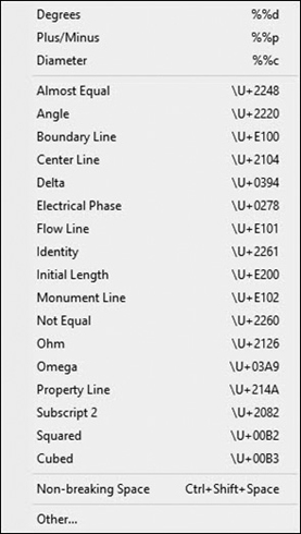
Figure 11-24 The Symbols menu
Selecting the Other… menu item at the bottom of the menu displays the Character Map dialog box shown in Figure 11-25 so you can insert symbols that are not included on the menu. This dialog box contains the entire character set for every available font. To insert a symbol from the Character Map dialog box, you must first select a symbol and then click the Select button to place it in the Characters to copy box. To insert the symbol, you must select the Copy button to copy the symbol to the Windows Clipboard. You can then switch back to the multiline editor in AutoCAD and paste the selected symbol in the desired location.

Figure 11-25 The Character Map dialog box
Note
The Character Map dialog box is actually a separate program that shows up on the Windows taskbar when you display it. It must be closed and exited manually. If you do not close the dialog box, you might find yourself running multiple copies of the program if you repeatedly display it.
The Field button allows you to insert a field using the Field dialog box. Fields and the Field dialog box are explained in detail later in this chapter.
Exercise 11-5 Creating Lists and Inserting Symbols
![]() Continue from Exercise 11-4.
Continue from Exercise 11-4.
![]() Set the NOTES text style current.
Set the NOTES text style current.
![]() Create the following bulleted list of multiline text within an area that is 4″ wide and 4″ tall:
Create the following bulleted list of multiline text within an area that is 4″ wide and 4″ tall:
This is a degree symbol °
This is a plus/minus symbol ±
This is a diameter symbol ø
This is a boundary line symbol BL
This is a centerline symbol CL
This is a delta symbol Δ
This is a property line symbol PL
![]() Change the bulleted list to a lettered list.
Change the bulleted list to a lettered list.
![]() Change the lettered list to a numbered list.
Change the lettered list to a numbered list.
![]() Save the drawing.
Save the drawing.
The Spell Check Panel. The Spell Check button turns on and off the Check Spelling As You Type feature that allows you to check spelling as you enter text in the multiline text editor. Any word you enter is checked for spelling errors when it is completed so that any word that is misspelled is underlined in red. Spelling suggestions display when you right-click the underlined word.
The Edit Dictionaries button displays the Dictionaries dialog box explained later in “The Spell Checker” section so you can switch dictionaries to check spelling in other languages, add new words to a dictionary, and perform other dictionary management tasks.
The Tools Panel. The Find & Replace tool displays the Find and Replace dialog box shown in Figure 11-26 so you can search for a specific string of text and replace it with a new string of text.
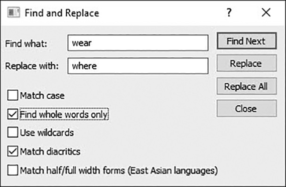
Figure 11-26 The Find and Replace dialog box
The Find what: text box is where you enter the text you want to search for.
The Replace with: text box is where you enter the replacement text for the text entered in the Find what: text box.
Selecting the Match case check box allows you to search for text that matches the uppercase and/or lowercase of the text entered in the Find what: text box exactly.
Selecting the Find whole words only check box allows you to search only for text as a complete word with a space before and after; otherwise, the search will also find text that is part of a word.
The Use wildcards check box allows the use of wildcard characters in searches. For more information on wildcard searches, see the “Finding and Replacing Text” section later in this chapter.
The Match diacritics check box allows you to match diacritical marks, or accents, in search results.
The Match half/full width forms (East Asian languages) check box matches half- and full-width Asian characters in search results.
After all the search criteria are entered, you can choose one of three options:
Select the Find Next button to search for and highlight the next occurrence of the search text.
Select the Replace button to replace the highlighted text in the multiline text editor to update the text with the text entered in the Replace with: text box.
Select the Replace All button to search for and replace all the text in the multiline text editor that matches the search criteria with the text entered in the Replace with: text box. A message box is displayed indicating how many occurrences were replaced so that you know whether, and how many, text strings were replaced.
The Import Text button on the expanded panel allows you to import an ASCII (American Standard Code for Information Interchange) text file or an RTF (Rich Text Format) text file into the multiline text editor. Selecting the Import Text button displays the Select File dialog box shown in Figure 11-27 so you can navigate your computer or network and find the text file to import.

Figure 11-27 Importing a text file into the multiline text editor
Once you locate the file, select it so it is highlighted, and select the Open button to import the text. You can then edit the text if necessary using the standard methods explained in this chapter.
Tip
You can store text that is used in multiple drawings in an external text file so that you don’t have to type the text in every drawing. For instance, you might store general notes in a file named General Notes.txt. If you locate the file on a network, all team members can then import the same text file. This approach both provides consistency and increases production.
The All CAPS button on the expanded panel turns the All CAPS feature on and off. All CAPS can be used much like the <Caps Lock> key to lock your keyboard so only uppercase letters can be entered. This is a handy feature in the drafting field because most drawing notes are uppercase according to industry standards.
Note
The All CAPS feature overrides the <Caps Lock> key so that it cannot be used to toggle uppercase on and off. You can hold down the <Shift> key in order to type lowercase.
The Options Panel. The Ruler tool toggles the ruler on and off. Once the ruler is turned off, it remains off the next time you display the in-place multiline text editor. See the preceding section “The Ruler” for detailed information about the ruler feature.
The Undo tool undoes actions in the multiline text editor, including changes to either text content or text formatting.
The Redo tool redoes actions in the multiline text editor, including changes to either text content or text formatting.
The More tool displays a menu with a few other multiline text options and features that are also located on the right-click menu explained in the next section.
The Right-Click Menu
The right-click shortcut menu shown in Figure 11-28 provides additional multiline text options and features, as well as access to some of the same features found on the Text Editor context tab of the ribbon explained earlier.
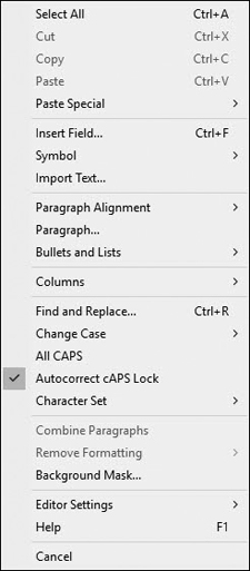
Figure 11-28 The right-click shortcut menu
The right-click shortcut menu can be displayed by right-clicking with your mouse anywhere in the multiline text editor window. At the top of the menu are a few specific text-editing commands:
Select All Selects all the text in the text editor
Cut Deletes text and places it on the Windows Clipboard so you can paste it later
Copy Copies text to the Windows Clipboard so you can paste it later
Paste Inserts text that is currently on the Windows Clipboard
Paste Special Displays a cascade menu that allows you to perform the following special paste operations:
Paste without Character Formatting Pastes and ignores any character-based formatting such as font, text height, etc. while maintaining any paragraph-based formatting such as justification, line spacing, etc.
Paste without Paragraph Formatting Pastes and ignores any paragraph-based formatting such as justification, line spacing, etc. while maintaining any character-based formatting such as font, text height, etc.
Paste without Any Formatting Ignores all original formatting and uses the current formatting
The Insert Field… menu item allows you to insert a field using the Field dialog box. Fields and the Field dialog box are explained in detail later in this chapter.
The Symbol menu item displays a cascade menu that allows you to insert a symbol or a nonbreaking space at the current cursor position. The Symbol cascade menu is the same as the Symbols menu displayed when you select the Symbol button on the Insert panel on the Text Editor context tab of the ribbon. See the preceding section “The Insert Panel” for complete information about using the Symbols menu.
The Import Text… menu item allows you to import a text file using the Select File dialog box shown in Figure 11-27.
The Paragraph Alignment menu item displays a cascade menu with the same horizontal paragraph justification, text flow, and spacing options found in the Paragraph Alignment area in the Paragraph dialog box shown earlier in Figure 11-21 in the “The Paragraph Panel” section:
The Left option aligns text on the left-hand margin so text flows right.
The Center option centers text on the centerline of the text boundary so text flows both directions.
The Right option aligns text on the right-hand margin so text flows left.
The Justified option spreads text out to fill the text boundary width by putting space between words.
The Distributed option spreads text out to fill the text boundary width by putting space between letters.
The Paragraph… menu item displays the same Paragraph dialog box shown earlier in Figure 11-21 in the “The Paragraph Panel” section so that you can control tabs, indents, paragraph alignment, and other paragraph features and settings. Please see the “The Paragraph Panel” section for detailed information regarding the Paragraph dialog box.
The Bullets and Lists menu item displays the same Bullets and Lists cascade menu shown earlier in Figure 11-20 in the “The Paragraph Panel” section so that you can create lettered, numbered, or bulleted lists. Please see the “The Paragraph Panel” section for detailed information regarding the Bullets and Lists menu.
The Columns menu item displays the same Columns cascade menu shown earlier in Figure 11-22 in the “The Insert Panel” section so that you can create dynamic and static columns. Please see the “The Insert Panel” section for detailed information regarding the Columns menu.
The Find and Replace… menu item displays the same Find and Replace dialog box shown earlier in Figure 11-26 so you can search for a specific string of text and replace it with a new string of text. Please see the “The Tools Panel” section for detailed information regarding the Find and Replace dialog box.
The Change Case menu item displays the cascade menu shown in Figure 11-29. This menu can be used to change the selected text to all uppercase or all lowercase.
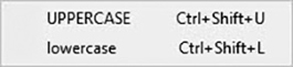
Figure 11-29 Change Case cascade menu
The All CAPS menu item turns on and off the All CAPS feature explained earlier.
The AutoCorrect cAPS Lock menu item turns on and off the AutoCorrect cAPS Lock feature, which recognizes whether the <Caps Lock> key is turned on while holding the <Shift> key. The feature enables you to automatically correct the text and turn off the <Caps Lock> key so you can continue typing without interruption.
The Character Set menu item displays the cascade menu shown in Figure 11-30. The Character Set menu item can be used to change the character set used so that text in other languages appears properly.

Figure 11-30 Character Set cascade menu
character set: The set of numeric codes used by a computer system to represent the characters (letters, numbers, punctuation, etc.) of a particular country or place.
The Combine Paragraphs menu item will combine multiple paragraphs of selected text together, removing any line feeds so that the selected text becomes one paragraph. The original text properties are retained.
The Remove Formatting menu item displays a cascade menu that provides different options for removing the formatting overrides for selected text so that those overrides revert back to the text’s assigned text style:
Remove Character Formatting Removes any character-based formatting such as font, text height, etc., while maintaining any paragraph-based formatting such as justification, line spacing, etc.
Note
The Remove Formatting menu item is displayed only when text is selected in the multiline text editor.
Remove Paragraph Formatting Removes any paragraph-based formatting such as justification, line spacing, etc., while maintaining any character-based formatting such as font, text height, etc.
Remove All Formatting Removes all formatting.
The Background Mask… menu item displays the Background Mask dialog box shown earlier in Figure 11-19 so you can set the background of one text boundary box opaque and set its color.
The Editor Settings menu item displays a cascade menu that allows you to control the following multiline text editor display features:
Always Display as WYSIWYG
Show Toolbar Turns the Text Formatting toolbar on and off
Show Options Turns the bottom portion of the Text Formatting toolbar on and off
Show Ruler Turns the Ruler on and off
Opaque Background Allows you to make the background of the editor opaque. By default, the editor is transparent
Check Spelling Turns the Check Spelling As You Type feature on and off. This option is on by default
Check Spelling Settings… Displays the Check Spelling Settings dialog box so you can specify text options that will be checked for spelling errors within your drawing
Dictionaries… Displays the Dictionaries dialog box so you can control the dictionary that is checked against any found misspelled words
Text Highlight Color… Allows you to change the color used to highlight text
Help displays the multiline text help topic.
Exercise 11-6 Using the Right-Click Menu
![]() Continue from Exercise 11-5.
Continue from Exercise 11-5.
![]() Using Windows Notepad, create a text file that contains the following text:
Using Windows Notepad, create a text file that contains the following text:
This is text that is in an external file named Notes.txt that I am
going to import into the multiline text editor and reformat.
![]() Save the file as Notes.txt in a location where you can find it, and exit the Notepad program.
Save the file as Notes.txt in a location where you can find it, and exit the Notepad program.
Tip
The Notepad program can typically be started by selecting the Windows Start button and navigating to the Accessories folder. You can also start Notepad by typing Notepad<Enter> in AutoCAD.
![]() Switch back to AutoCAD and start the MTEXT command.
Switch back to AutoCAD and start the MTEXT command.
![]() Define a text boundary area 2″ wide by 2″ tall.
Define a text boundary area 2″ wide by 2″ tall.
![]() Using the right-click menu, do the following:
Using the right-click menu, do the following:
a. Import the Notes.txt text file.
b. Set the background mask to red.
c. Set the paragraph alignment to Center.
d. Find all occurrences of the word “text” and replace it with “test.”
e. Make all the text uppercase.
![]() Save the drawing.
Save the drawing.
Stacked Text
By default, AutoCAD automatically stacks text representing a fraction or tolerance so that the left character is placed on top of the right character as a horizontal fraction, diagonal fraction, or tolerance based on the following special stack characters:
^ Caret converts to left-justified tolerance values.
/ Forward slash converts to a center-justified fraction with a horizontal bar.
Backward slash converts to a center-justified fraction with a horizontal bar.
# Pound sign converts to a fraction with a diagonal bar the height of the two text strings.
When text is automatically stacked, a lightning bolt icon is displayed, which when clicked on displays the AutoStack context menu shown in Figure 11-31 with different stacking options.

Figure 11-31 The AutoStack context menu
Options include switching between diagonal and horizontal stacking formats, unstacking a fraction, and the ability to further refine the process via the Stack Properties dialog box.
Stack Properties Dialog Box. The Stack Properties dialog box shown in Figure 11-32 allows you to edit the text content, stack type, alignment, and size of stacked text. To display the dialog box, you must first select existing stacked text, right-click with your mouse, and select Stack Properties from the shortcut menu. The following options are available:
The Upper and Lower text boxes in the Text section allow you to change the upper and lower numbers of a stacked fraction.
The Appearance section allows you to edit the style, position, or text size of a stacked fraction.
The Style list allows you to switch between the horizontal fraction, diagonal fraction, and tolerance stacking styles.
The Position list allows you to switch between the following text alignments:
Top Aligns the top of the fraction with the top of the previous text
Center Centers the fraction vertically at the center of the previous text
Bottom Aligns the bottom of the fraction with the previous text

Figure 11-32 The Stack Properties dialog box
Note
Both the Top text and the Bottom text use the same alignment specified.
The Text size list controls the size of the stacked text as a percentage relative to the size of the whole number text height. Valid values are between 25% and 125%. The default text size is 70%.
The Defaults button allows you to either restore the default stacked text properties or save the current stacked text properties as the new default.
The AutoStack… button displays the AutoStack Properties dialog box so you can either modify or turn off AutoStack properties.
AutoStack Properties Dialog Box. The AutoStack Properties dialog box shown in Figure 11-33 allows you to define specific text stacking properties that can be applied automatically as you type when a number is entered followed by any of the special stacking characters.

Figure 11-33 The AutoStack Properties dialog box
The Enable AutoStacking check box allows you to turn AutoStacking on and off. If checked, text is automatically stacked when a number is typed in followed by any of the special characters.
You can control whether a forward slash converts to a horizontal or diagonal fraction via the x/y becomes radio buttons. If the (diagonal fraction) button is selected, diagonal fractions are created. If the (horizontal fraction) button is selected, horizontal fractions are created.
The Remove leading blank: check box allows you to remove automatically any space between the whole number and the fraction if it is checked.
Exercise 11-7 Creating Stacked Text
![]() Continue from Exercise 11-6.
Continue from Exercise 11-6.
![]() Start the MTEXT command.
Start the MTEXT command.
![]() Define a text boundary area 3″ wide by 3″ tall.
Define a text boundary area 3″ wide by 3″ tall.
![]() Enter the following line of text in the multiline text editor and press <Enter>:
Enter the following line of text in the multiline text editor and press <Enter>:
THIS IS A HORIZONTAL STACKED FRACTION 1/2
![]() Enter the following line of text in the multiline text editor and press <Enter>:
Enter the following line of text in the multiline text editor and press <Enter>:
THIS IS A DIAGONAL STACKED FRACTION 1#2
![]() Enter the following line of text in the multiline text editor and press <Enter>:
Enter the following line of text in the multiline text editor and press <Enter>:
THIS IS A TOLERANCE VALUE 001^002
![]() Save the drawing
Save the drawing
Creating Single-Line Text
In addition to multiline text, you can also create what is referred to as single-line text to create one or more lines of text. Single-line text is the original text type in AutoCAD that preceded the more complex and feature-rich multiline text explored in the last section. With single-line text, each line of text is an independent object that can be modified. Multiple lines of single-line text can be entered at the same time in paragraph form with consistent vertical spacing between each line—it’s just that you must break each line at the end using the <Enter> key. See Figure 11-34.
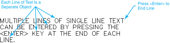
Figure 11-34 Single-line text
Single-Line Text |
|
|---|---|
Ribbon & Panel: |
Home | Annotation |
Menu: |
Draw | Text | Single Line Text |
Command Line: |
TEXT or DTEXT |
Command Alias: |
DT |
Note
Remember from the beginning of the chapter that if you set the current text style height to anything other than 0.00″ you will not be prompted for a text height when creating single-line text.
The TEXT command or the DTEXT command can be used to create single-line text.
When you start either command, AutoCAD displays the current text style and height at the command line as follows:
Current text style: "Standard" Text height: 0.2000
The text styles used for single-line text are the same as those used for multiline text, explained earlier. You can change the styles via the Style option explained below, although using the Text Style list box on the Text panel on the Annotate tab of the ribbon shown in Figure 11-4 is much easier as you will see. The text height can also be changed after you select the starting point for the text.
Note
By default, single-line text is left justified. This means that text that you type will flow to the right of the text start point. You can change the default justification using the justification options explained in one of the next sections.
After starting either command, AutoCAD prompts you to Specify start point of text or ![]() . Select a starting point for the text either by picking a point in your drawing or by entering a coordinate location via the keyboard.
. Select a starting point for the text either by picking a point in your drawing or by entering a coordinate location via the keyboard.
After locating the text start point, AutoCAD prompts you to Specify height <0,2000>:. Enter the desired text height and press <Enter>. The height entered becomes the default the next time you create single-line text.
After entering the height, AutoCAD prompts you to Specify rotation angle of text <0>:. Enter the desired text angle or press <Enter> to use the default.
Tip
You can also use your cursor to input the angle by selecting a point in response to the Specify rotation angle of text <0>: prompt. The text start point is used as the base point of the angle with the second point defining the angle. You can even utilize object snaps to align the text by snapping to points on existing objects.
After you enter the desired text angle, AutoCAD displays the no frills in-place single-line text editor, which is basically a dynamically sized box that grows longer as you type, as shown in Figure 11-35.

Figure 11-35 Entering single-line text
As mentioned, it is possible to create multiple lines of text using single-line text; however, you must input the line breaks manually by pressing <Enter> at the end of the line. Pressing <Enter> places the cursor on the next line in the in-place single-line text editor so you can continue typing as shown in Figure 11-36.
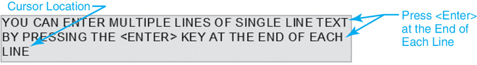
Figure 11-36 Entering multiple lines of single-line text
You can continue to add lines of text until you press the <Enter> key twice—meaning that you press <Enter> without entering any text on the current line. You can also pick a point outside the edit box with your mouse to end the command. Remember that each line of text is still a separate object even though it was all entered at the same time as shown in Figure 11-37.

Figure 11-37 Multiple lines of single-line text
Note
The line spacing used for single-line text is 1.5 times the text height from the bottom of one line of text to the bottom of the next line.
Tip
If TEXT or DTEXT was the last command entered, when you create additional new single-line text you can simply press <Enter> at the Specify start point of text or ![]() prompt and skip the prompts for a text height and rotation angle. AutoCAD automatically displays the in-place single-line text editor directly below the last line of text created in the drawing using the same height, rotation angle, and justification so you can just start typing!
prompt and skip the prompts for a text height and rotation angle. AutoCAD automatically displays the in-place single-line text editor directly below the last line of text created in the drawing using the same height, rotation angle, and justification so you can just start typing!
The Right-Click Menu
The single-line text editor also has the right-click menu shown in Figure 11-38, which provides additional functionality. The menu shares some of the same tools and features found on the right-click menu in the multiline text editor explained earlier:
Undo/Redo Allows you to undo/redo one or more actions in the text editor
Cut Deletes text and places it on the Windows Clipboard so you can paste it later
Copy Copies text to the Windows Clipboard so you can paste it later
Paste Inserts text that is currently on the Windows Clipboard
Editor Settings Cascade menu with the same editor options found in the multiline text editor
Insert Field… Allows you to insert a field using the Field dialog box. Fields and the Field dialog box are explained in detail later in this chapter.
Find and Replace… Displays the Find and Replace dialog box so you can search for and replace text
Select All Selects all the text in the single-line text editor
Change Case Cascade menu that allows you to change the case of text
UPPERCASE Changes text to uppercase
lowercase Changes text to lowercase
Help Displays the single-line text help topic
Cancel Exits the single-line text editor
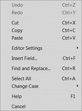
Figure 11-38 Single-line text editor right-click menu
Single-Line Text Justification
Single-line text has a justification property similar to multiline text that determines how the text is aligned relative to the insertion point, although unlike multiline text, single-line justification affects only one line of text, not the complete paragraph. The different justification options are shown in Figure 11-39.

Figure 11-39 Single-line text justification options
The single-line text justification options can be used to specify any of the justifications shown in Figure 11-39. The justification option that is selected is maintained until it is changed. To change the text justification, start the TEXT or DTEXT command, and select the justification option. AutoCAD prompts you to Enter an option:. After you select a justification, you specify a start point, height, and rotation angle using the methods explained earlier. The in-place single-line text editor is then displayed, and you can begin typing.
The text flow as you type is determined by the justification option chosen. Specifying Right justification makes text flow from the right to the left, whereas the Center justification option makes text spill out in both directions from the start point (see Figure 11-40).
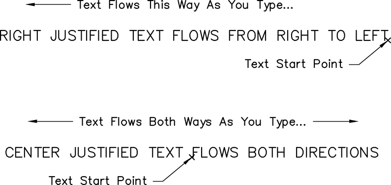
Figure 11-40 Using the Right and Center justification options
Except for the first two options, Align and Fit, most of the justification options are fairly self-explanatory. The Align and Fit justification options both allow you to locate text using two points to define the width and angle of the text. Both options force the text to fit between the two points specified—although with different methods. The Align option changes the height of the text (shorter or taller) to make the text fit, and the Fit option changes the text’s width scale factor (narrower or wider) to make the text fit.
To use the Align option, start the TEXT or DTEXT command and select the Align option using the methods explained above. AutoCAD prompts you to Specify first endpoint of text baseline:. Select the starting point for the text. AutoCAD then prompts you to Specify second endpoint of text baseline:. This point determines both the angle and the final overall width of the text. Remember that the Align option changes the height of the text in order to make it fit between the two points. Because of this, the in-place single-line text editor box starts out tall and gets shorter as you type, as shown in Figure 11-41.
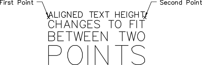
Figure 11-41 Using the Align justification option
To use the Fit option, start the TEXT or DTEXT command, and select the Fit option using the methods explained above. AutoCAD prompts you to Specify first endpoint of text baseline:. Select the starting point for the text. AutoCAD then prompts you to Specify second endpoint of text baseline:. This point determines both the angle and final overall width of the text. The Fit option changes the width scale factor of the text in order to make it fit between the two points. Because of this, AutoCAD prompts you to Specify height <0.1000>:. After you enter the desired height, the in-place single-line text editor box is displayed, and you can begin typing. The text is either expanded or compressed to fit between the two points as you type but the height is maintained as shown in Figure 11-42.

Figure 11-42 Using the Fit justification option
Exercise 11-8 Creating Single-Line Text
![]() Continue from Exercise 11-7.
Continue from Exercise 11-7.
![]() Create the single-line text shown in Figure 11-43 using the text style, height, and justification indicated.
Create the single-line text shown in Figure 11-43 using the text style, height, and justification indicated.
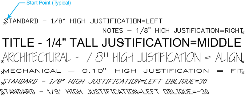
Figure 11-43 Creating single-line text
![]() Save the drawing.
Save the drawing.
Inserting Special Symbols in Single-Line Text
You can insert a number of the same special symbols using the single-line text editor that you can insert using the multiline text editor, but your options are somewhat limited. There is no access to the Character Map dialog box, and the symbols you can use must be typed in using either their corresponding AutoCAD “%%” control code or their “U+” Unicode string. The available AutoCAD control codes are as follows:
%%C Draws circle diameter dimensioning symbol (ø)
%%D Draws degree symbol (°)
%%P Draws plus/minus tolerance symbol (±)
%%O Toggles overscoring on and off
%%U Toggles underscoring on and off
%%% Draws a single percent sign (%)
The control codes are immediately converted into their corresponding symbols as you type. For instance, entering %%D in the single-line text editor inserts the degree symbol shown in Figure 11-44.

Figure 11-44 Using the %%D control code to insert a degree symbol
Note
You can use underscoring and overscoring at the same time.
The underscore (%%U) and overscore (%%O) control codes are toggles that can be turned on and off as shown in Figure 11-45.

Figure 11-45 Using the %%U and %%O control codes to underscore and overscore text
Tip
You can also insert the Euro symbol. If your keyboard does not have a Euro symbol key, you hold down the <Alt> key and enter 0128 via the numeric keypad.
Exercise 11-9 Inserting Symbols in Single-Line Text
![]() Continue from Exercise 11-8.
Continue from Exercise 11-8.
![]() Set the STANDARD text style current.
Set the STANDARD text style current.
![]() Create the single-line text shown in Figure 11-46 at 0.1250 high, 0° rotation angle, and justification set to Left.
Create the single-line text shown in Figure 11-46 at 0.1250 high, 0° rotation angle, and justification set to Left.

Figure 11-46 Inserting symbols in single-line text
![]() Save the drawing.
Save the drawing.
Text Fields
A field is intelligent text you can insert in your drawing that dynamically updates according to the data it is based on and/or represents. A classic example is the Date field. You can create a Date field in a drawing that automatically updates to reflect the current date, and even time, using a variety of different formats:
2/3/2017
Friday, February 03, 2017
2017-02-03
3-Feb-17
…
Fields can be created by themselves, so they stand alone, or they can be inserted in any kind of text, attribute, or attribute definition. A field uses the same text style as the text object in which it is inserted and is displayed with a light gray background that is not plotted.
When a field is updated, the latest data are displayed. Fields can be set to update automatically via one or all of the following events and actions:
When a drawing is opened
When a drawing is saved
When a drawing is plotted
When you use eTransmit
When a drawing is regenerated
It is also possible to turn off all the automatic update features so you must manually update any fields in a drawing. You can control how fields are updated, and then turn the field background display on and off in the Fields area at the bottom left of the User Preferences tab of the Options dialog box shown in Figure 11-47.
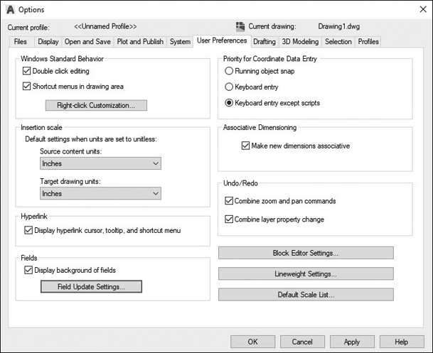
Figure 11-47 Fields settings on the User Preferences tab of the Options dialog box
Unchecking the Display background of fields check box turns off the light gray background. Selecting the Field Update Settings… button displays the Field Update Settings dialog box shown in Figure 11-48.

Figure 11-48 The Field Update Settings dialog box
Note
A field that currently has no value displays all hyphens (--). For instance, the PlotDate field is not set to anything until a drawing is plotted. An invalid field displays all pound signs (####).
This dialog box allows you to indicate what actions or events will automatically update fields. By default, they are all on. If you uncheck all the check boxes, you must update fields manually.
Insert Field |
|
|---|---|
Ribbon & Panel: |
Insert | Data |
Menu: |
Insert | Field… |
Command Line: |
FIELD |
Command Alias: |
None |
Inserting Text Fields
There are several different ways to insert a field. To create a single stand-alone field, you use the FIELD command.
To insert a field into multiline text, you can either select Insert Field… from the multiline editor right-click menu (see Figure 11-28), or you can use the Field button on the Insert panel on the Text Editor context tab of the ribbon explained earlier (see Figure 11-15). To insert a field into single-line text, you must select Insert Field… from the single-line editor right-click menu explained earlier. Any of these methods displays the Field dialog box shown in Figure 11-49.

Figure 11-49 The Field dialog box
The Field category: list box lists the different types of fields available broken down into the following categories:
All All fields
Date & Time Date/time–related fields (created, saved, plotted)
Document Drawing file–related fields (file name, size, saved by)
Linked Hyperlink information
Objects Object information (formulas, block names, drawing object properties)
Other Miscellaneous information (diesel expressions, system variable values)
Plot Plot information (plot device, paper size, scale)
Sheetset Sheet set information
The Field names: list box changes based on the category selected. All the other options in the Field dialog box change based on the field category and field name that are selected. For instance, selecting the Date & Time field category displays a list of the following date-related field names:
CreateDate
Date
PlotDate
SaveDate
All the date fields allow you to specify a date format in the Date format: text box and control how the date appears in the drawing. You can either enter your own format via the keyboard using the control codes shown in the Hints area on the right side of the Field dialog box or, even easier, selecting a predefined format from the Examples: list in the middle of the dialog box shown in Figure 11-50.

Figure 11-50 The Field dialog box with the Date & Time options
The Field expression: box displays the actual field expression that underlies the field and cannot be edited. It is possible to use the field expression as a guide so that you can construct your own expressions in the Date format: text box.
When you have selected the desired field name and all its formatting options, you can select OK to insert the field. Figure 11-51 shows a Date field inserted in a multiline text object.

Figure 11-51 A Date field inserted into a paragraph of multiline text
Editing Text Fields
Text fields are part of either a multiline or single-line text object. If you insert a stand-alone field as described earlier, it is created as multiline text. Because of this, you must use the same tools to edit a field as you do to edit multiline and single-line text. When a field is selected, the Edit Field option is available on the shortcut menu, or you can double-click the field to display the Field dialog box. Any changes are applied to all text in the field.
Tip
If you no longer want to update a field, you can preserve the value that is currently displayed by converting the field to text.
Exercise 11-10 Inserting Text Fields
![]() Continue from Exercise 11-9.
Continue from Exercise 11-9.
![]() Set the NOTES text style current.
Set the NOTES text style current.
![]() Start the TEXT or DTEXT command to create single-line text.
Start the TEXT or DTEXT command to create single-line text.
![]() Pick a start point for the text anywhere in your drawing.
Pick a start point for the text anywhere in your drawing.
![]() Enter a rotation angle of 0° when AutoCAD prompts you to Specify rotation angle of text<0>:.
Enter a rotation angle of 0° when AutoCAD prompts you to Specify rotation angle of text<0>:.
![]() Enter the following text followed by a space but do not press the <Enter> key:
Enter the following text followed by a space but do not press the <Enter> key:
Drawing plotted on:
![]() Right-click with your mouse while still in the single-line text editor, and select Insert Field… from the shortcut menu (see Figure 11-38) to display the Field dialog box (see Figure 11-49).
Right-click with your mouse while still in the single-line text editor, and select Insert Field… from the shortcut menu (see Figure 11-38) to display the Field dialog box (see Figure 11-49).
![]() Select Date & Time from the Field category: list box to display the Date & Time field names.
Select Date & Time from the Field category: list box to display the Date & Time field names.
![]() Select PlotDate from the Field names: list box.
Select PlotDate from the Field names: list box.
![]() Select OK to insert the field.
Select OK to insert the field.
![]() Press <Enter> twice to exit the TEXT command.
Press <Enter> twice to exit the TEXT command.
![]() The text should read as follows:
The text should read as follows:
Drawing plotted on: - - - -
![]() Plot your drawing to any plotting device or file.
Plot your drawing to any plotting device or file.
![]() Text is updated so that it looks similar to the following, only with today’s date:
Text is updated so that it looks similar to the following, only with today’s date:
Drawing plotted on: 5/8/2019
![]() Save the drawing.
Save the drawing.
Editing Text
Both multiline and single-line text can be modified using any of the modify commands introduced earlier in the book. You can move, copy, rotate, scale, and array text just like any other drawing object. Multiline text can even be broken down into individual single-line text objects using the EXPLODE command.
You can also use grips to modify text. Both single-line text and multiline text can be moved using the grip located at the text insertion point. Multiline text also has grips that can be used to resize the boundary area using the Stretch option, as shown in Figure 11-52.
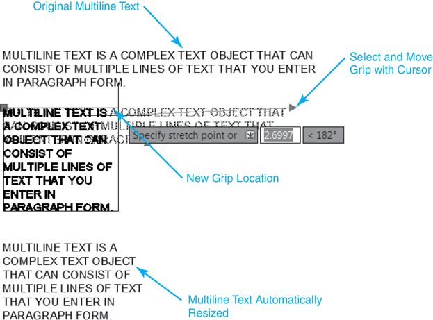
Figure 11-52 Using grips to resize the multiline text boundary
Editing Text Content
The easiest way to edit the text content is to simply double-click on the text you want to edit. If you double-click on multiline text, the same in-place multiline text editor used to create the text is displayed with the selected text, as shown in Figure 11-53. You can then update the text and any of its properties using the same methods and techniques introduced earlier.
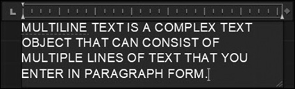
Figure 11-53 Editing text using the multiline text editor
Edit Text |
|
|---|---|
Ribbon & Panel: |
None |
Menu: |
Modify Object | Text |Edit |
Command Line: |
DDEDIT |
Command Alias: |
ED |
Double-clicking on single-line text displays the in-place single-line text editor shown in Figure 11-54.

Figure 11-54 Editing text using the single-line text editor
You can also use the DDEDIT or ED command to edit text content. After starting the DDEDIT command, select the text to edit and press <Enter>. AutoCAD displays either the in-place multiline or single-line text editor depending on the type of text selected. You can then update the text using the methods and techniques explained earlier.
Tip
The TEXTEDIT command’s Mode option (TEXTEDITMODE = 1) allows you to edit multiple text objects without having to restart the command. When the Multiple option is selected, TEXTEDIT repeats, so you can continue to select text objects until you are done editing.
Editing Text Using the Properties Palette
The Properties palette allows you to change all facets of a text object, including text content, text style, height, justification, and rotation, to name but a few. Plus, using the Properties palette, you can also change the text’s general properties, such as layer, color, and so on. It’s the Swiss army knife of text-editing tools. The properties of a multiline text object are shown in Figure 11-55.
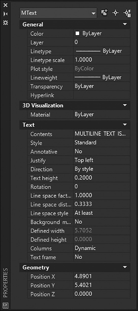
Figure 11-55 Properties of a multiline object
Selecting the button to the right of the Contents property displays the appropriate text editor so you can update the text contents as explained earlier.
Note
You can create a border around multiline text by setting its Text frame property to Yes on the Properties palette.
Tip
You can update multiple text objects using the Properties palette. For instance, you can use the Properties palette to update the text height for all text in a drawing. In fact, you can even update the text height for both single-line and multiline text at the same time.
Exercise 11-11 Editing Text
![]() Continue from Exercise 11-10.
Continue from Exercise 11-10.
![]() Select the multiline text created in Exercise 11-2 so grips are displayed.
Select the multiline text created in Exercise 11-2 so grips are displayed.
![]() Select the top-right-corner grip and stretch the text boundary corner to the right (see Figure 11-52).
Select the top-right-corner grip and stretch the text boundary corner to the right (see Figure 11-52).
![]() Press the <Esc> key to turn off grips.
Press the <Esc> key to turn off grips.
![]() Double-click on the multiline text object to display the in-place multiline text editor.
Double-click on the multiline text object to display the in-place multiline text editor.
![]() Resize the text width back to 3″ using the arrows on the right-hand side of the ruler (see Figure 11-15)
Resize the text width back to 3″ using the arrows on the right-hand side of the ruler (see Figure 11-15)
![]() Press <Ctrl>+A to select all the text in the editor.
Press <Ctrl>+A to select all the text in the editor.
![]() Use the Text Editor context tab of the ribbon to change the following:
Use the Text Editor context tab of the ribbon to change the following:
a. Set the style for all text to ARCHITECTURAL.
b. Make all text uppercase.
c. Deselect all text so nothing is highlighted by clicking anywhere in the text editor window with your cursor.
d. Select the text “in-place editor” on the first line so it is highlighted.
e. Change the selected text to bold and italic.
f. Set the first line indent to 1″ and the paragraph indent to 0.5″ using the ruler.
![]() Select OK or click outside the multiline text editor to exit and save your changes.
Select OK or click outside the multiline text editor to exit and save your changes.
![]() Double-click on any of the single-line text objects to display the in-place single-line text editor.
Double-click on any of the single-line text objects to display the in-place single-line text editor.
![]() Type the following over the highlighted text:
Type the following over the highlighted text:
THIS IS SOME NEW TEXT!
![]() Press <Enter> to exit the editor.
Press <Enter> to exit the editor.
![]() Hit <Esc> to exit the DDEDIT command.
Hit <Esc> to exit the DDEDIT command.
![]() Select all the text in the drawing and open the Properties palette (see Figure 11-55).
Select all the text in the drawing and open the Properties palette (see Figure 11-55).
![]() Change the height property to 0.1″ to update the text height for all the selected text.
Change the height property to 0.1″ to update the text height for all the selected text.
![]() Change the justification property to Right for all the selected text.
Change the justification property to Right for all the selected text.
![]() Press <Esc> to deselect all the text.
Press <Esc> to deselect all the text.
![]() Save the drawing.
Save the drawing.
Text Alignment
The TEXTALIGN command allows you to quickly align single-line and multiline text, as well as block attributes, by selecting the text to align and then picking the text you wish to align with as shown in Figure 11-56 or by selecting two points to manually define an alignment line.
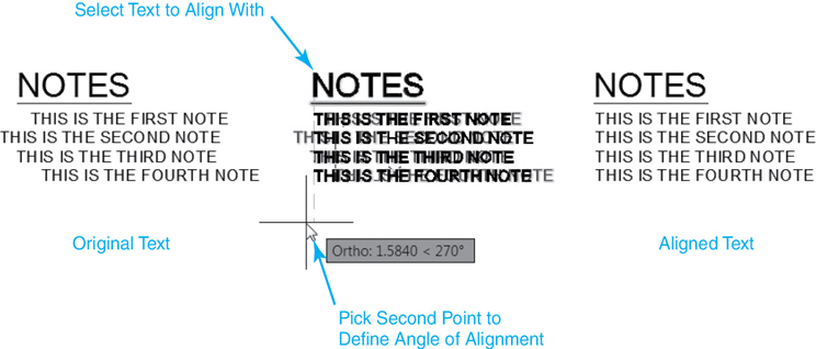
Figure 11-56 Aligning text with the TEXTALIGN command
Text Align |
|
|---|---|
Ribbon & Panel: |
Annotate | Text |
Menu: |
None |
Command Line: |
TEXTALIGN |
Command Alias: |
None |
The alIgnment option allows you specify a different alignment direction. Options allows you to choose from a variety of spacing options, including the ability to distribute the text evenly, set a spacing value, and maintain the current vertical or horizontal spacing.
Scaling Text
The SCALETEXT command allows you to change the height of one or more text objects using the following methods using a base point that you specify:
Specifying a new height
Specifying a scale factor
Matching the height of an existing text object
Scale Text |
|
|---|---|
Ribbon & Panel: |
Annotate | Text |
Menu: |
Modify Object| Text |Scale |
Command Line: |
SCALETEXT |
Command Alias: |
None |
You can elect to use each text object’s insertion point as the base point about which the text is scaled, or you can select one of the different justification options explained earlier in the chapter. AutoCAD uses the base point to scale each text object, but it doesn’t change the justification point for each object, as shown in Figure 11-57.
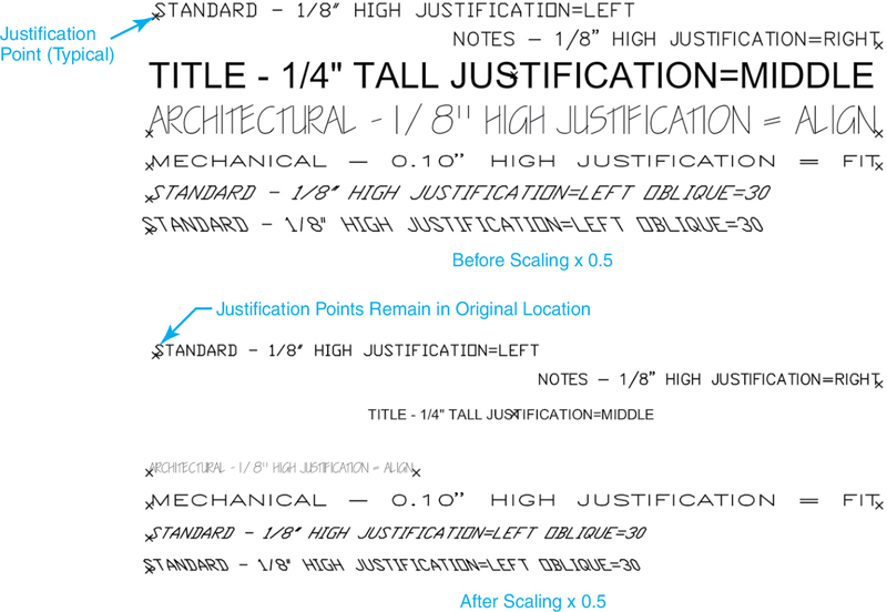
Figure 11-57 Changing text height using the SCALETEXT command
When you start the SCALETEXT command, AutoCAD prompts you to Select objects:. Select the text you want to update using any of the selection methods, and press <Enter>. AutoCAD prompts you to Enter a base point option for scaling:. You can press <Enter> to use the existing text insertion points as base points, or you can select one of the different justification options. Remember that the justification point entered is used only as a temporary base point for each text object.
After you have selected a base point option, AutoCAD prompts you to Specify new height or ![]() . You have three options: you can enter a new height, you can specify a scale factor to multiply each text height by, or you can match the height of an existing text object in the drawing. The default is to enter a new height.
. You have three options: you can enter a new height, you can specify a scale factor to multiply each text height by, or you can match the height of an existing text object in the drawing. The default is to enter a new height.
Exercise 11-12 Scaling Text
![]() Continue from Exercise 11-11.
Continue from Exercise 11-11.
![]() Start the SCALETEXT command.
Start the SCALETEXT command.
![]() Type ALL and press <Enter> twice when AutoCAD prompts you to Select objects: to select everything in the drawing.
Type ALL and press <Enter> twice when AutoCAD prompts you to Select objects: to select everything in the drawing.
![]() AutoCAD prompts you to Enter a base point option for scaling
AutoCAD prompts you to Enter a base point option for scaling ![]() .
.
![]() Type E<Enter> or select the existing option using your arrow keys.
Type E<Enter> or select the existing option using your arrow keys.
![]() AutoCAD prompts you to Specify new height or
AutoCAD prompts you to Specify new height or ![]() .
.
![]() Type .1<Enter>.
Type .1<Enter>.
![]() All the text is resized to 0.1″ tall using its current insertion point.
All the text is resized to 0.1″ tall using its current insertion point.
![]() Save the drawing.
Save the drawing.
Changing Text Justification
The JUSTIFYTEXT command allows you to change the justification property of one or more text objects without changing their location in the drawing. Typically, when you change the justification property of text using the Properties palette, the text is relocated about the new justification point as shown in Figure 11-58.
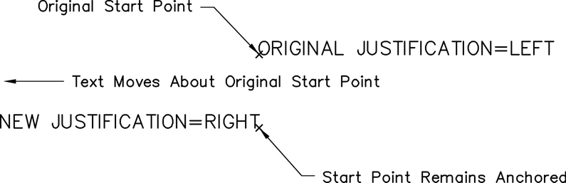
Figure 11-58 Changing text justification using the Properties palette
Justify Text |
|
|---|---|
Ribbon & Panel: |
Annotate | Text |
Menu: |
Modify Object | Text | Justify |
Command Line: |
JUSTIFYTEXT |
Command Alias: |
None |
The JUSTIFYTEXT command provides a way around this problem. When you start the JUSTIFYTEXT command, AutoCAD prompts you to Select objects:. Select the text you want to update using any of the selection methods and press <Enter>. AutoCAD prompts you to Enter a justification option: so you can select one of the different justification options. The insertion points for all the selected text objects are changed to the justification point specified, but they remain in their original locations as shown in Figure 11-59.
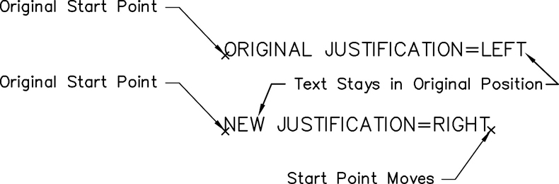
Figure 11-59 Changing text justification using the JUSTIFYTEXT command
Exercise 11-13 Changing Text Justification
![]() Continue from Exercise 11-12.
Continue from Exercise 11-12.
![]() Start the JUSTIFYTEXT command.
Start the JUSTIFYTEXT command.
![]() Type ALL and press <Enter> twice when AutoCAD prompts you to Select objects: to select everything in the drawing.
Type ALL and press <Enter> twice when AutoCAD prompts you to Select objects: to select everything in the drawing.
![]() AutoCAD prompts you to Enter a justification option
AutoCAD prompts you to Enter a justification option ![]() .
.
![]() Select the Right justification option.
Select the Right justification option.
![]() All the text justification points are changed to Right, but the text remains in its original location.
All the text justification points are changed to Right, but the text remains in its original location.
![]() Save the drawing.
Save the drawing.
Finding and Replacing Text
The FIND command allows you to find and replace text that you specify. AutoCAD searches through all the different text types in a drawing including:
Single-line and multiline text
Block attributes
Dimensions
Tables
Hyperlinks
Find Text |
|
|---|---|
Ribbon & Panel: |
Annotate | Text |
Menu: |
Edit | Find… |
Command Line: |
FIND |
Command Alias: |
None |
It is possible to limit what type of text to search for so you can refine your search via the FIND command’s options explained later. When you start the FIND command, AutoCAD displays the Find and Replace dialog box shown in Figure 11-60.
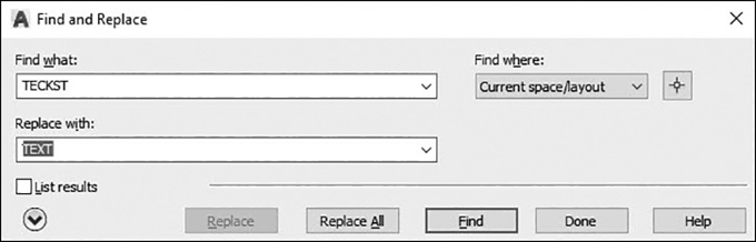
Figure 11-60 The Find and Replace dialog box
The Find what: combo box is where you type in the text string for which you want to search. You can enter a text string or choose one of the recently used strings from the list. It is also possible to use wildcard characters to enhance your search possibilities.
Tip
You can enter text directly via the box to the left of the Find Text button on the Text panel on the Annotate tab of the ribbon. Selecting the Find Text button automatically starts the search for the first match and displays the Find and Replace dialog box.
The Replace with: combo box is where you type in the text string you want to replace for any found text. You can enter a text string or choose one of the recently used strings from the list.
The Find where: list box allows you to specify where to search. You can search the current space/layout, the entire drawing, or selected objects. If one or more objects are already selected, the Current selection option is the default value; otherwise, the Current space/layout option is the default.
The Select objects button to the right of the Find where: list box closes the dialog box temporarily so that you can select objects in your drawing. Accepting the selection set by pressing <Enter> returns to the dialog box.
The More Options arrow button on the lower left expands the dialog box as shown in Figure 11-61 so you can view and modify the search options and text types to search.
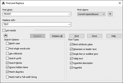
Figure 11-61 The Find and Replace dialog box with more options
The Replace button replaces the found text with the text that you enter in the Replace with: combo box.
The Replace All button finds all occurrences of the text entered in the Find what: combo box and replaces them with the text entered in the Replace with: combo box. AutoCAD reports the success or failure of the replacement attempt in a separate dialog box by indicating how many objects have been changed.
The Find button in the Find and Replace dialog box searches for the text that you enter in the Find what: combo box. Any text that is found is automatically zoomed into so you can see it in context. After finding the first occurrence of the text, the Find button becomes the Find Next button to allow you to search for the next text occurrence.
Selecting the List results check box displays a table with the text location (model or paper space), object type, and text string where the text was found, showing it in context. Clicking on a column header in the table sorts the information based on the content in that column.
When List results are displayed, the Zoom button on the right allows you to zoom to the highlighted object. Additional buttons allow you to quickly create a selection set that includes all text objects in the list or only the highlighted items.
Selecting the More Options arrow button expands the dialog box so you can specify different search options and text types to search.
The different Search Options include:
Match case Includes the case of the text in Find what: as part of the search criteria
Find whole words only Finds only whole words that match the text in Find what:. For example, if you select Find whole words only and search for “is”, Find and Replace does not locate the text string “this”.
Use wildcards Allows the use of the following wildcard characters in searches:
Find and Replace Wildcard Characters
Wildcard Character
Description
* (Asterisk)
Matches any text string
@ (At)
Matches any letter only
# (Pound)
Matches any number only
? (Question mark)
Matches any single character (letters and numbers)
. (Period)
Matches any nonalphanumeric character
~ (Tilde)
Matches anything but the pattern
[ ] (Square brackets)
Matches any of the characters enclosed in the brackets
[~] (Tilde)
Matches any character not enclosed in the brackets
[-] (Hyphen and brackets)
Specifies a range for a single letter
′ (Reverse quote)
Reads the next character literally
Search xrefs Includes text in externally referenced files in search results
Search blocks Includes text in blocks in search results
Ignore hidden items Ignores hidden items in search results. Hidden items include text on layers that are frozen or turned off, text in block attributes created in invisible mode, and text in visibility states within dynamic blocks.
Match diacritics (Latin-based languages) Matches diacritical marks, or accents, in search results
Match half or full width forms (East Asian Languages) Matches half- and full-width characters in search results
The Text Types area allows you to specify the type of text objects you want to include in the search. By default, all options are selected.
The Done button closes and exits the Find and Replace dialog box.
Tip
The FIND command can also be found near the bottom of many of the right-click menus for easy access.
Exercise 11-14 Finding and Replacing Text
![]() Continue from Exercise 11-13.
Continue from Exercise 11-13.
![]() Type the word text in the Find Text box on the Text panel of the Annotate tab.
Type the word text in the Find Text box on the Text panel of the Annotate tab.
![]() Select the Find Text button on the right to display the Find and Replace dialog box shown in Figure 11-60.
Select the Find Text button on the right to display the Find and Replace dialog box shown in Figure 11-60.
![]() Type the word teckst in the Replace with: list box.
Type the word teckst in the Replace with: list box.
![]() Select the Replace button to replace the current text.
Select the Replace button to replace the current text.
![]() Select the Find Next button to find the next occurrence.
Select the Find Next button to find the next occurrence.
![]() Select the Replace All button to replace all the text in the drawing.
Select the Replace All button to replace all the text in the drawing.
![]() Note how many matches were found and how many objects were changed and select the OK button.
Note how many matches were found and how many objects were changed and select the OK button.
![]() Select the Done button to exit the dialog box.
Select the Done button to exit the dialog box.
![]() Save the drawing.
Save the drawing.
The Spell Checker
The SPELL command allows you to check and correct the spelling for the following text object types:
Single-line and multiline text
Dimensions
Block attribute values
External references
Check Spelling |
|
|---|---|
Ribbon & Panel: |
Annotate | Text |
Menu: |
Tools | Spelling… |
Command Line: |
SPELL |
Command Alias: |
SP |
Entering the SPELL command displays the Check Spelling dialog box shown in Figure 11-62.
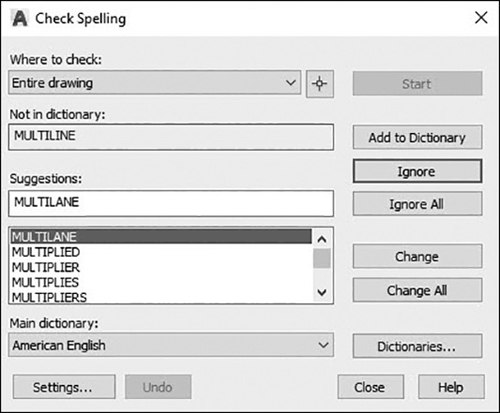
Figure 11-62 The Check Spelling dialog box
The Where to check: drop-down list allows you to limit where and what text AutoCAD checks for spelling errors. You have the following three options:
Entire drawing
Current space/layout
Selected objects
By default, AutoCAD checks the entire drawing for spelling errors. If you select Selected objects, you must select some text objects in the drawing by selecting the Select objects button to the right of the Where to check: drop-down list. Otherwise, the Start button will be disabled.
Select the Start button to begin the spell-checking process. If no misspelled words are found, AutoCAD displays a message box indicating that the Spelling Check is complete. Otherwise, AutoCAD will automatically zoom to the first misspelled word in the drawing and highlight the offending text.
The Not in dictionary: area displays the highlighted word that is spelled incorrectly or was not found in the current dictionary. This is the text that will be updated if you select the Change or Change All button.
The Suggestions: box displays a list of suggested replacement words from the current dictionary. You can either select a replacement word from the list or type in a replacement word in the box.
The Add to Dictionary button adds the current word to the current custom dictionary. A different custom dictionary can be selected using the Dictionaries… button explained below.
The Ignore button skips the current word and begins searching for the next misspelled word.
The Ignore All button skips all the remaining occurrences of the misspelled word that match the current word.
The Change button replaces the current word with the word in the Suggestions: text box.
The Change All button replaces all occurrences of the misspelled word in the drawing based on the current Where to check: selection.
The Dictionaries… button displays the Dictionaries dialog box shown in Figure 11-63.
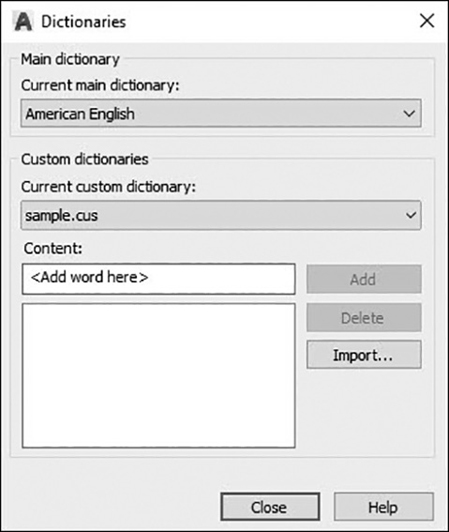
Figure 11-63 The Dictionaries dialog box
The Dictionaries dialog box allows you to switch dictionaries so you can check spelling in other languages. The default main dictionary is American English. To change to another language dictionary, select it from the Current main dictionary: list box at the top.
To add one or more words to the dictionary, enter it in the Content: text box, and select the Add button. Any words you add in the Check Spelling dialog box or the Dictionaries dialog box are stored in the custom dictionary. By default, the custom dictionary is named sample.cus and is located in your AutoCAD Support folder.
Note
The maximum word length you can add to a custom dictionary is 63 characters
You can manage custom dictionaries by selecting Manage custom dictionaries… from the Current custom dictionary: drop-down list to display the Manage Custom Dictionaries dialog box. The Manage Custom Dictionaries dialog box allows you to add dictionaries to check, create new dictionaries from scratch, and remove existing dictionaries.
The Settings… button in the Check Spelling dialog box displays the Check Spelling Settings dialog box shown in Figure 11-64, which allows you to control various aspects of the spell-checking behavior.

Figure 11-64 The Check Spelling Settings dialog box
At the top of the Check Spelling Settings dialog box in the Include area, you can choose whether to check dimension text, block attributes, or external references.
At the bottom of the dialog box in the Options area, you can choose to ignore certain types of words commonly found in technical drawings such as words with numbers and words containing punctuation.
Tip
The Undo button allows you to undo changes if you change the wrong text.
Exercise 11-15 Using the Spell Checker
![]() Continue from Exercise 11-14.
Continue from Exercise 11-14.
![]() Start the SPELL command.
Start the SPELL command.
![]() The Check Spelling dialog box is displayed.
The Check Spelling dialog box is displayed.
![]() Select the Start button.
Select the Start button.
![]() AutoCAD zooms to the word “teckst” in your drawing while also displaying it in the Not in dictionary: text box.
AutoCAD zooms to the word “teckst” in your drawing while also displaying it in the Not in dictionary: text box.
![]() Suggestions: is set to “text”.
Suggestions: is set to “text”.
![]() Select the Change button to update the current text.
Select the Change button to update the current text.
![]() The next occurrence of “teckst” is found.
The next occurrence of “teckst” is found.
![]() Select the Change All button to update all occurrences of the misspelled word.
Select the Change All button to update all occurrences of the misspelled word.
![]() The Spelling Check is complete message box is displayed.
The Spelling Check is complete message box is displayed.
![]() Select OK.
Select OK.
![]() Save the drawing.
Save the drawing.
The Combine Text Tool
The Combine Text tool enables you to combine many individual text objects into one multiline text object.
Combine Text |
|
|---|---|
Ribbon & Panel: |
Insert | Import |
Menu: |
None |
Command Line: |
TXT2MTXT |
Command Alias: |
None |
The selected text objects are replaced by one or more multiline text objects. If possible, the text size, font, and color differences between text objects are maintained.
The Settings option displays the Text to MText Settings dialog box shown in Figure 11-65, which allows you to control the following aspects of the Combine Text tool behavior:
Combine into a single mtext object Combines selected text objects into a single mtext object
Text ordering
Sort top-down Specifies the order of the selected text by descending vertical position
Select order of text Specifies the order of the selected text by manual selection
Word-wrap text Combines all text into a single line, then wraps any text that exceeds the width of the mtext object to the next line
Force uniform line spacing Applies consistent interline spacing and paragraph spacing when word wrap is turned on
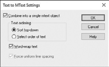
Figure 11-65 The Text to MText Settings dialog box
Chapter Summary
Text and notes are key features of any type of technical drawing. They literally help to communicate the idea that the drawings are trying to convey. It is important that text meet specific standards of appearance so that it is as clear and concise as possible, limiting the chance for errors or omissions. Standard fonts and heights must be applied on all drawings so that all text has the same look and feel. AutoCAD text styles provide the best control over text appearance because all of the settings, such as font and height, are centralized in one location instead of being applied individually for each text object in a drawing.
AutoCAD provides two different types of text: multiline and single line. Each serves its own purpose. Many times you will want to rely on single-line text for short notes, titles, and labels in a drawing. Other times you may want the benefits of multiline text, which allows you to create different list types, use multiple columns, and insert many different special symbols. Multiline text is the default used for most commands, but remember that you can always break up multiline text into multiple single-line text objects using the EXPLODE command. The easiest way to edit both types of text is simply to double-click on the text you want to change, and then AutoCAD will display the proper text-editing tool based on whether text is multiline or single line. Of course, you can always use the Properties palette to change the text content or any other property for that matter.
Advanced text tools help increase productivity and accuracy. Text fields allow you to automate text in a drawing so that you can insert text that will automatically update with the current date, when the drawing was plotted, the drawing name, and much more. The Find and Replace tool can be used to update text for an entire drawing in one step. The Spell Checker can scan and fix text for an entire drawing using a standard dictionary or a custom dictionary that can include your own key terms and abbreviations.
Chapter Test Questions
Multiple Choice
Circle the correct answer.
1. A font determines how text looks by defining its:
a. Boldness
b. Typeface
c. Language
d. All of the above
2. AutoCAD fonts have what three-letter file extension?
a. SHP
b. FNT
c. TTF
d. SHX
3. The system variable that controls the font substituted for a font not found on your system is named:
a. ALTFONT
b. FONTSUB
c. SUBFONT
d. FONTALT
4. To exit the in-place multiline text editor and save your text and any changes, you:
a. Select Close Text Editor on the Text Editor context tab of the ribbon
b. Press <Ctrl>+<Enter>
c. Click outside the editor window with your mouse
d. All of the above
5. The system variable that controls the default text height displayed in the multiline text editor Text height list box is:
a. TEXTHEIGHT
b. SIZETEXT
c. TXTHEIGHT
d. TEXTSIZE
6. The name of the feature in the multiline text editor that locks your keyboard so only uppercase letters can be typed is:
a. CaseLock
b. All CAPS
c. CapLocks
e. CapAuto
7. The AutoStack feature automatically stacks numeric text when what character is placed between two numbers?
a. /
b. #
c. ^
d. All of the above
8. What single-line justification option allows you to squeeze text between two points without changing the text height?
a. Align
b. Fit
c. Center
None of the above
9. The prefix used to insert special symbols into single-line text is:
a. @
b. %%
c. U++
d. b and c
10. To edit existing text, you can:
a. Double-click on the text
b. Use the Properties palette
c. Use the DDEDIT command
d. All of the above
Matching
Write the number of the correct answer on the line.
a. Annotate ______ |
1. System variable that controls the filling of TrueType fonts while plotting and rendering |
b. Typeface ______ |
2. Locks your keyboard so only uppercase letters can be entered, similar to the <Caps Lock> key |
c. TEXTFILL ______ |
3. The set of numeric codes used to represent the characters of a particular country or place |
d. FONTALT ______ |
4. Controls the font, height, and other characteristics that affect the appearance of text |
e. Text style ______ |
5. Creates different formats of stacked text as you type |
f. Multiline text ______ |
6. To add text, notes, and dimensions to a drawing |
g. All CAPS ______ |
7. Intelligent text that dynamically updates according to the data it is based on and/or represents |
h. Character set ______ |
8. System variable that specifies an alternate font to be used when a particular font file cannot be located on your system |
i. AutoStack ______ |
9. Complex text object that can consist of multiple lines of text that you enter in paragraph form |
j. Field ______ |
10. The style or design of a font |
True or False
Circle the correct answer.
1. True or False: The text font determines the height of the text in a drawing.
2. True or False: You can use both TrueType fonts and AutoCAD SHX fonts in a drawing at the same time.
3. True or False: You should always try to use text styles to control text fonts.
4. True or False: If you change a text style text height, all text of that style in a drawing is updated.
5. True or False: It is possible to resize a multiline text boundary size using grips.
6. True or False: You can copy text to and from the multiline text editor using the Windows Clipboard.
7. True or False: The Import Text… option in the multiline editor allows you to import a Microsoft Word document.
8. True or False: The All CAPS feature in the multiline editor can be turned off using your <Caps Lock> key.
9. True or False: If the current text style has a height assigned in the style that is greater than 0.0, you will be prompted for a text height when creating single-line text.
10. True or False: The single-line Align text justification option will change the text height in order to make the text entered fit between two selected points.
Chapter Projects
 Project 11-1: Calculator, continued from Chapter 10 [BASIC]
Open drawing P10-1 from Chapter 10.
Add the text shown in Figure 11-66. Hint: Use multiline text with the Middle Center justification option.
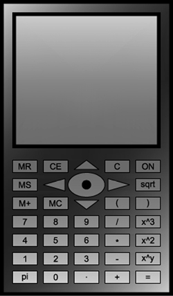
Figure 11-66
Save your drawing as P11-1.
 Project 11-2: B-Size Mechanical Border, continued from Chapter 6 [INTERMEDIATE]
Open the template file Mechanical B-Size.DWT from Project 6-2 in Chapter 6.
Modify the Standard text style to use the ROMANS.SHX font file.
Set the snap to 1/16>, and add the text shown in Figure 11-67 on the layer Title. Large text is 1/8> tall, and smaller text is 1/16>. Use multiline text for the tolerance note and single-line text for all other text. Use text fields for the drawing name and plot date.
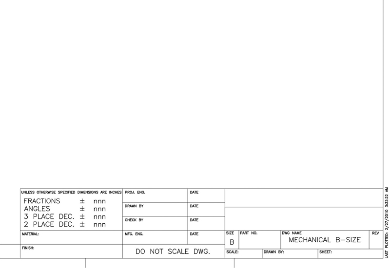
Figure 11-67
Save the drawing to a template file as Mechanical B-Size.DWT.
 Project 11-3: Architectural D-Size Border, continued from Chapter 10 [ADVANCED]
Open the template file Architectural D-Size.DWT from Project 10-3 in Chapter 10.
Create a text style named Border assigned the text font Simplex.shx.
Create a text style named Logo assigned the text font Century Gothic.ttf.
Create a text style named Arch assigned the text font CountryBlueprint.ttf.
Create all text in the following steps at the approximate heights shown. Try to use standard heights when possible.
Create all the logo text as shown in Figure 11-68 using the text style Logo on the layer A-Anno-Ttlb-Logo.
Create the text on the bottom left that says, “Last plotted on MM/DD/YYYY” by inserting the date as a field using the PlotDate field so it updates each time the drawing is plotted.
Create all the remaining title border text as shown in Figure 11-68 using the text style Border on the layer A-Anno-Ttlb-Text.

Figure 11-68
Save the drawing to a template file as Architectural D-Size.DWT.
 Project 11-4: Electrical Distribution Panel, continued from Chapter 10 [BASIC]
Open drawing P10-4 from Chapter 10.
Add the electrical annotation shown in Figure 11-69. Place all annotation on the E-Anno layer.

Figure 11-69
Save your drawing as P11-4.
Project 11-5: Residential Architectural Plan, continued from Chapter 10 [ADVANCED]
Open drawing P10-5 from Chapter 10.
Create the following layers:
Name
Color
Linetype
Lineweight
Description
A-Door-Iden
White
Continuous
0.30 mm
Door tags
A-Glaz-Iden
White
Continuous
0.30 mm
Window tags
A-Area-Iden
White
Continuous
0.30 mm
Room numbers, room identification, and area calculations
A-Anno-Legn
White
Continuous
0.30 mm
Door and window schedules
A-Anno-Note
White
Continuous
0.30 mm
General notes
A-Anno-Dims
White
Continuous
0.30 mm
Dimensioning
Create a text style called A-SYMBOL using the ROMANS.SHX font and set it current.
Create the door and window schedules and tags as shown in Figure 11-70 using lines and text. Use a text height of 6> for the door and window tags and the small text in the schedule. Use a text height of 8> for the column heads in the table and a text height of 12> for the schedule titles.

Figure 11-70
Place the door and window tags and add the room labels as shown in Figure 11-71. Place each object on its appropriate layer.
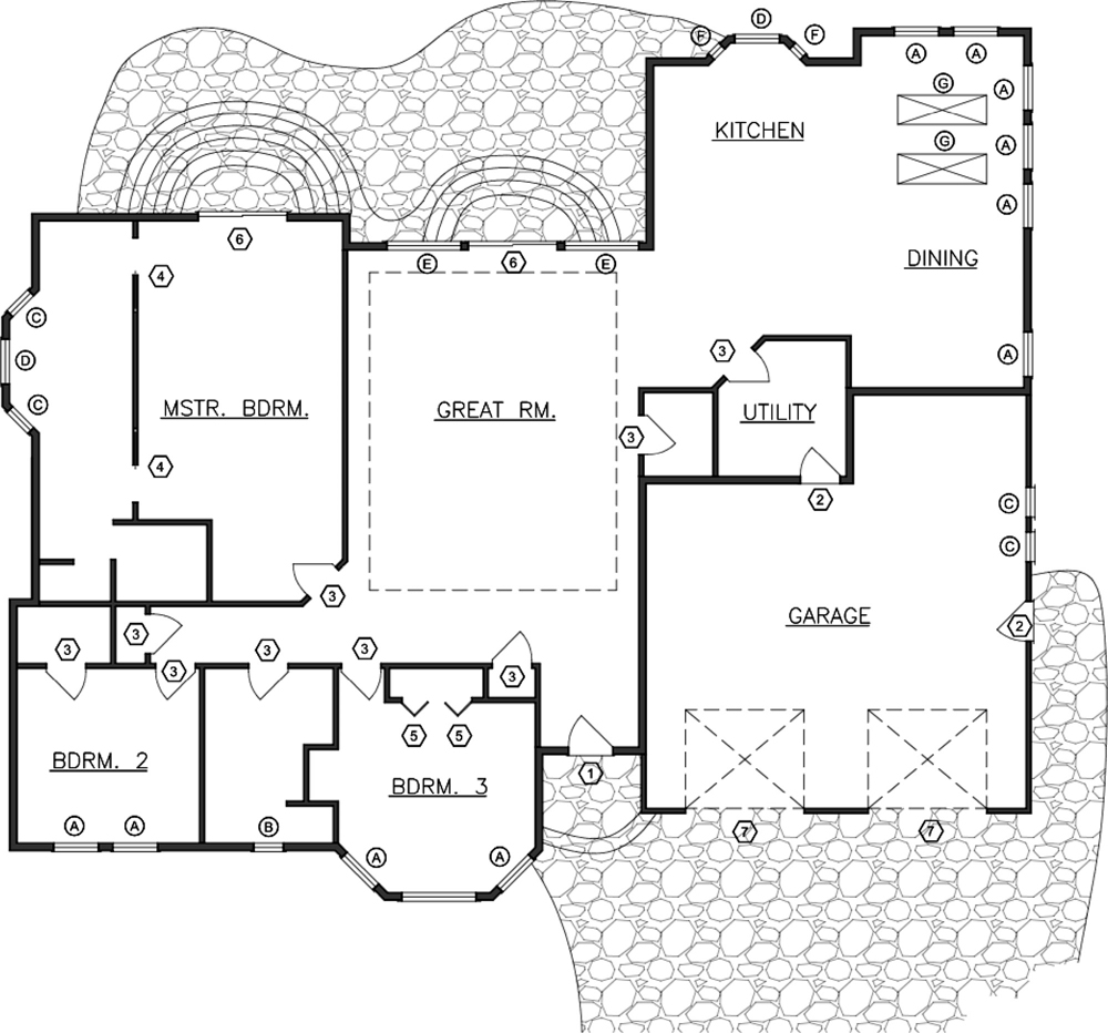
Figure 11-71
Save the drawing as P11-5.