Chapter Ten: Pattern Fills and Hatching
Chapter Objectives
Select a hatch boundary area
Control hatch settings and options
Modify hatched areas
Match the settings of existing hatched areas
Create solid and gradient fills
Edit hatched areas
Use DesignCenter to create hatch objects
Introduction
Hatching is the process of filling in a closed area with a pattern. This is typically used in cross-section or elevation drawings to denote different material usage. Hatch patterns can consist of lines and dots as well as solid colors and gradient fill patterns. Hatching must be placed within a closed area, which means that the edges of the hatch area cannot contain any gaps or openings. AutoCAD provides a couple of different ways to create and select hatch boundaries. In this chapter, you’ll look at how hatch patterns are created, controlled, and modified.
hatching: The process of filling in a closed area with a pattern.
Hatching
Figure 10-1 shows some different hatched areas. The hatch boundary defines the area of the hatch. Hatch islands are closed areas inside the outer hatch boundary. When you hatch an area, you can control how island areas are dealt with. The hatch pattern is the pattern used to fill in the boundary. The hatch pattern has a scale, rotation angle, and origin associated with it as well.
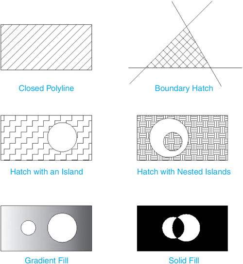
Figure 10-1 Hatch and gradient fill examples
hatch boundary: The edges of a hatched area.
hatch islands: Closed areas within a hatch boundary.
hatch pattern: The pattern used to fill a hatch boundary.
Hatch |
|
|---|---|
Ribbon & Panel: |
Home | Draw |
Menu: |
Draw | Hatch… |
Command Line: |
HATCH/BHATCH |
Command Alias: |
H |
The HATCH command is used to place different hatch patterns. All of the hatch settings and options are controlled via the Hatch Creation context tab of the ribbon shown in Figure 10-2, which is displayed after you start the command.

Figure 10-2 The Hatch Creation context tab of the ribbon
Selecting a Hatch Area
There are two ways to select hatch boundaries. The default method is to pick an internal point within a closed boundary area. The other method is to select objects that form a closed area such as circles and closed polylines.
Picking an Internal Point. When you pick an internal point, AutoCAD will search out from the point you pick and attempt to trace a closed area around the point you selected. If it’s successful, AutoCAD will highlight the closed area and allow you to select additional points. This is a quick and easy way to create hatch areas.
Selecting Objects. If you select closed areas (such as circles or closed polylines) AutoCAD will simply hatch inside them. If you select open objects (such as lines, arcs, and open polylines), AutoCAD will attempt to calculate a hatch area. If the open objects are placed end to end and clearly define a closed area, then the results are predictable. However, if you choose overlapping objects, or if the objects don’t clearly define a closed area, then your hatch area may not turn out the way you intend. Figure 10-3 shows some examples of selecting open and closed objects for hatch boundaries.

Figure 10-3 Selecting hatch boundaries
Exercise 10-1 Picking an Internal Boundary Point
![]() Open drawing EX10-1 located in the student data files.
Open drawing EX10-1 located in the student data files.
![]() Start the HATCH command.
Start the HATCH command.
![]() Place your cursor near where point 1 is shown in Figure 10-4 but do not pick a point yet. Notice the hatch preview.
Place your cursor near where point 1 is shown in Figure 10-4 but do not pick a point yet. Notice the hatch preview.
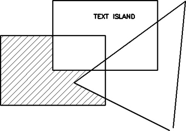
Figure 10-4 Picking boundary points
![]() Pick a point at the location indicated in Figure 10-4, and press <Enter> to accept the hatch pattern.
Pick a point at the location indicated in Figure 10-4, and press <Enter> to accept the hatch pattern.
![]() Save the drawing as CH10_EXERCISE1. Your drawing should look like Figure 10-5.
Save the drawing as CH10_EXERCISE1. Your drawing should look like Figure 10-5.
Figure 10-5 The hatched area
To access student data files, go to www.pearsondesigncentral.com.
Controlling Hatch Settings and Options
There are two ways to control hatch settings and options: either by selecting the seTtings option at the command line before accepting the boundary area definition to display the Hatch and Gradient dialog box introduced in the next section or by using the Hatch Creation context tab of the ribbon shown in Figure 10-2.
The Hatch and Gradient Dialog Box. The Hatch and Gradient dialog box, shown in Figure 10-6, is a legacy method of controlling the hatch settings and options. It has been superseded by the Hatch Creation context tab of the ribbon for the most part. A brief overview only is provided.
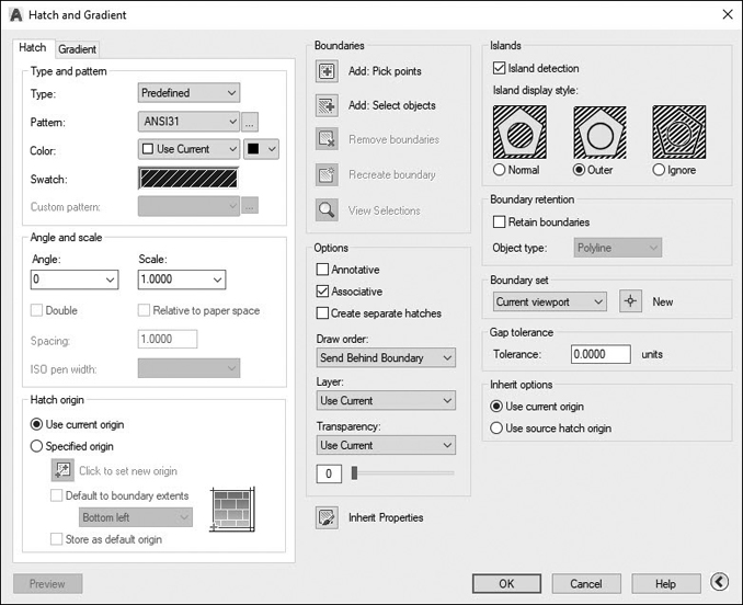
Figure 10-6 The Hatch and Gradient dialog box
The Hatch and Gradient dialog box is divided into three general sections. The Hatch and Gradient tabs on the left side of the dialog box allow you to control how the hatch looks. The Boundaries area in the center of the dialog box allows you to select or create a hatch area and controls how the hatch will behave. The right side of the dialog box allows you to control how hatch boundaries are created and how island areas are treated.
Note
If your Hatch and Gradient dialog box doesn’t show all the options, select the arrow in the lower-right corner of the dialog box. This will expand the dialog box to show all the options for the HATCH command.
The Hatch Creation Context Tab of the Ribbon. The Hatch Creation context tab of the ribbon is displayed and becomes the current tab when you start the HATCH command. You can change most settings and options on the fly either before or after defining the hatch boundary area. The different ribbon panels are explored in the following sections.
Boundaries Panel. The Boundaries panel provides different options for selecting and adjusting the boundary area. The different ways of selecting the boundary area were discussed earlier. The other boundary options are explained in the following sections.
Adding and Removing Boundaries. Once you have selected a hatch area, you can add additional boundaries by either selecting objects or picking additional points. You can also remove boundaries using the Remove button. You can simply select the boundary to remove from the selection when prompted.
Retaining the Boundary. When you create a boundary hatch, you have the option of keeping the boundary as either a polyline or a region. When either of the Retain Boundaries options is selected, AutoCAD will create a boundary on the same layer as the hatch pattern. By default, boundaries are not retained.
Note
You must select the down arrow at the bottom of the Boundaries panel to display the expanded panel for the Retain Boundaries and Boundary Set options.
Tip
If your drawing has a lot of hatching or contains complex boundaries, you may wish to retain your hatch boundaries and place the boundaries and hatch patterns on a separate layer. This allows you to make changes easily to the hatch patterns and boundaries and also allows you to turn off complex patterns that can sometimes get in the way when editing your drawing.
Boundary Sets. The Boundary Set options allow you to control which objects are used when detecting a boundary. The boundary set is a set of objects used to determine boundaries when picking points. By default, everything that is visible in the current viewport is used as the boundary set. If there are objects you wish to ignore or only certain objects you wish to use, select the Select New Boundary Set button on the left side of the list box to create a new boundary set. The boundary set is reset to all objects upon completion of the HATCH command.
Tip
With large drawings, AutoCAD can sometimes take a while to calculate boundary areas. If this is the case, you may want to create a new boundary set or consider turning off or freezing layers to reduce the number of calculations needed to determine the boundary.
Pattern Panel. In addition to defining the boundary of the hatch area, you will also typically want to specify the hatch pattern appearance that is used to fill the defined area. AutoCAD comes with many predefined patterns that you can select from the Pattern panel. In fact, it is not obvious, but you can display most of them by selecting the arrow with the horizontal line on the bottom of the list box, as shown in Figure 10-7.
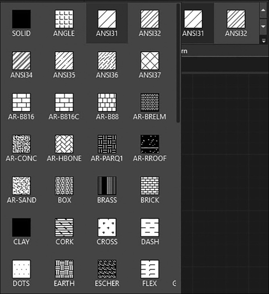
Figure 10-7 The expanded Pattern list
AutoCAD hatch patterns are similar to AutoCAD linetypes. By default, they are defined in an external text file named ACAD.PAT that can be either customized or completely replaced with another hatch pattern file. All of the hatch pattern definitions contained in the ACAD.PAT file are shown in Figure 10-8.
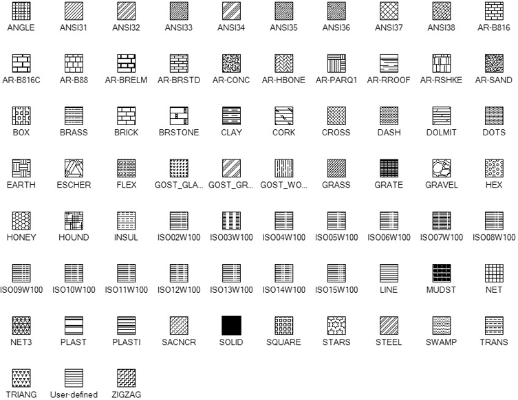
Figure 10-8 Hatch pattern definitions
As you can see, there are many different types of hatch patterns for many different applications for various disciplines. The hatch patterns with the ANSI prefix are typically used to denote different materials in section on mechanical drawings. Each numbered pattern represents a specific type of material. For instance, the ANSI32 hatch represents steel. The default is the ANSI31 hatch type, which is represented with 45° lines spaced 18″ apart. Not only does this represent the material iron, but it is also the industry standard pattern for any material in section.
Note
There are actually two hatch pattern definition files: the default used for imperial units (ACAD.PAT) and another that is set up for metric units (ACADISO.PAT). The ACADISO.PAT hatch pattern file contains the same hatch definitions as the ACAD.PAT file, but they are scaled to appear correctly in a metric drawing. You can switch between imperial and metric units by setting the MEASUREMENT variable to 0 for imperial and 1 for metric.
The hatch patterns with the AR- prefix are architectural-type hatches and represent different brick patterns, concrete, and earth, to name just a few. These hatch types indicate the actual sizes of the material they represent, so they need to be scaled accordingly. For instance, the AR-B816 hatch pattern represents an 8″×16″ block and is exactly 8″ tall by 16″ long. This allows you to hatch an exterior wall elevation for a building and show the block with the correct number of block courses.
Hatch patterns with the ISO prefix are metric patterns that are designed to comply with the ISO/DIS 12011 linetype specification. When you select an ISO pattern, the ISO Pen Width drop-down list is enabled on the Properties panel, explained later, so you can specify a pen width for the lines that make up the pattern.
Tip
You can select a hatch pattern either before or after defining the hatch boundary area. In fact, you can change most of the properties of a hatch pattern via the Hatch Creation context tab of the ribbon until you press <Enter> and accept your selections.
Properties Panel. The Properties panel shown in Figure 10-9 provides control over features that include hatch type, color, transparency, angle, scale, layer, and ISO pen width.
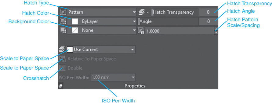
Figure 10-9 The Properties panel
Hatch Type. There are four different hatch types that you can choose from. The default Pattern hatch type provides access to all the built-in AutoCAD hatch pattern types discussed earlier, such as the ANSI standard and architectural (AR)-type hatches. The Solid hatch type allows you to hatch an area with a solid fill. The Gradient hatch type, discussed a little later in this chapter, allows you to apply one- and two-color solid fills with different shading effects.
The User defined hatch type allows you to define a hatch pattern consisting of straight lines at a defined angle and spacing. The user-defined pattern can have either a single set of parallel lines or a double set of perpendicular lines. The current linetype is used to draw the hatch pattern.
The appearance of the User defined hatch type is typically controlled via the Hatch Angle and Hatch Spacing options. Hatch Angle controls the angle of the lines (a setting of 0 produces horizontal lines; 90 produces vertical lines). Hatch Spacing is the spacing between the parallel lines. When the Double option is selected on the expanded Properties panel, an additional set of lines will be drawn perpendicular to the first set of hatch lines to create a crosshatch effect. The perpendicular hatch lines will have the same spacing as the parallel hatch lines. Figure 10-10 shows some examples of user-defined patterns.
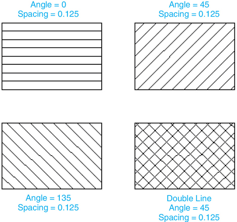
Figure 10-10 User defined hatch patterns
Hatch Color. Overrides the current color for hatch patterns or specifies the first of two gradient colors.
Background Color. Specifies the color for hatch pattern backgrounds or the second gradient color.
Hatch Transparency. Overrides the current transparency level for new hatch patterns. Select the Use Current button on the left to use the current object transparency setting.
Hatch Angle. Specifies an angle for the hatch pattern relative to the X-axis.
Hatch Pattern Scale/Spacing. Scales up or down predefined hatch patterns or sets the spacing for user-defined hatch patterns if the User defined pattern type is selected.
Hatch Layer Override. Overrides the current layer setting for new hatch patterns. Select the Use Current button on the left to use the current layer.
Tip
You can also set the Hatch Layer Override via the HPLAYER system variable. In fact, the HPLAYER system variable allows you to specify a nonexistent layer and AutoCAD will create it with the default layer settings.
Scale to Paper Space. Automatically scales the hatch pattern relative to the current viewport scale in paper space. This option is available only from a layout.
Crosshatch. Creates a crosshatch by drawing a second set of lines at 90° to the original lines for user-defined hatch types. This option is available only when Hatch Type is set to User defined.
ISO Pen Width. Scales an ISO predefined pattern based on the selected pen width. This option is available only when an ISO type pattern has been selected.
Exercise 10-2 Hatch Pattern Properties
![]() Continue from Exercise 10-1.
Continue from Exercise 10-1.
![]() Start the HATCH command so the Hatch Creation context tab of the ribbon is displayed.
Start the HATCH command so the Hatch Creation context tab of the ribbon is displayed.
![]() Select the ANSI32 hatch pattern from the Pattern panel, and pick a point where indicated in Figure 10-11 to create the hatch pattern. Do not press <Enter> yet.
Select the ANSI32 hatch pattern from the Pattern panel, and pick a point where indicated in Figure 10-11 to create the hatch pattern. Do not press <Enter> yet.

Figure 10-11 The boundary pick point
![]() Select the ANSI37 hatch pattern from the Pattern panel.
Select the ANSI37 hatch pattern from the Pattern panel.
![]() Enter 2 in the Hatch Pattern Scale box on the Properties panel, and press <Enter>.
Enter 2 in the Hatch Pattern Scale box on the Properties panel, and press <Enter>.
![]() Enter 45 in the Hatch Angle box on the Properties panel, and press <Enter>.
Enter 45 in the Hatch Angle box on the Properties panel, and press <Enter>.
![]() Set the color to red in the Hatch Color list box on the Properties panel.
Set the color to red in the Hatch Color list box on the Properties panel.
![]() Press <Enter> to accept the hatch. Your drawing should look like Figure 10-12.
Press <Enter> to accept the hatch. Your drawing should look like Figure 10-12.
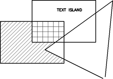
Figure 10-12 The completed hatch
![]() Save your drawing.
Save your drawing.
Origin Panel. The Origin panel area allows you to control the starting point of the hatch pattern. By default, all hatch patterns are drawn using 0,0 as a base point. This means that AutoCAD calculates where the hatch pattern will be drawn based on the hatch pattern definition starting at the 0,0 coordinate. Typically that is what you want; however, there may be times when you want the hatch pattern to start at a specific coordinate. For example, if you are using a brick or tile pattern, you may want the pattern to start with a full brick or tile in the corner of the boundary. To do this, you select the hatch origin to be the corner of the hatch boundary. Figure 10-13 shows some examples of setting the hatch origin.

Figure 10-13 Selecting a hatch origin
The Set Origin option allows you to select an origin point in your drawing. The Use Current Origin option simply uses the default hatch origin. By default this origin is 0,0 until you change it. It’s also possible to set the origin to default to one of the four corners (or the center) of the boundary area. Once you specify a new origin, select the Store as Default Origin button to retain that point at the new default hatch origin.
Options Panel. The Options panel provides different options that control the appearance and behavior of hatch patterns.
Associative Hatching. In AutoCAD, associativity means a link between one drawing object and another. In Chapter 2, you saw an example of associative dimensioning. When you placed a dimension object, it was associated with the points on the objects you dimensioned. If those points moved, the dimension object moved along with them.
Associativity can also occur between a hatch object and its boundary. If the boundary edge is modified, its associated hatch objects will update and fill in the changed boundary. The Associative option turns associativity on and off.
Note
Hatch pattern associativity can be a fleeting thing. Associativity can be lost if the boundary edges change significantly. For example, if two overlapping objects were used to create a hatch boundary, modifying the objects so that they no longer overlap will cause the hatch associativity to be lost. When hatch associativity is lost, AutoCAD will display a message in the command line window: Hatch boundary associativity removed.
Tip
If hatch associativity is removed, it is still possible to dynamically change the hatch boundary area by selecting it and using special intuitive grips. See Chapter 7 for information about using grips.
Annotative Hatching. The Annotative button turns automated annotation scaling on and off. If Annotative is on, the hatch pattern is automatically scaled up or down based on the current annotation scale
Gap Tolerance. If a boundary area contains gaps and is therefore not closed, AutoCAD displays a Boundary Definition Error dialog box and displays red circles showing where the gaps are located on the drawing. You can either fix them or adjust the Gap Tolerance. The Gap Tolerance setting allows you to heal any gaps in a boundary. When the gap tolerance is set to 0, the boundary must be completely closed in order for a valid boundary to be created. When the gap tolerance is set greater than 0, AutoCAD will attempt to determine a boundary and will ignore any gaps that are smaller than or equal to the specified tolerance. When it finds a valid boundary with gaps smaller than the specified tolerance, AutoCAD will display the Open Boundary Warning box (see Figure 10-14) asking whether you’d like to continue to hatch the area.

Figure 10-14 The Open Boundary Warning box
Note
You must select the down arrow at the bottom of the Options panel to access the Gap Tolerance and the other options discussed in the following sections.
When AutoCAD detects a boundary with gaps, it will project the objects out to their intersection and use this point as the corner of the boundary.
Creating Separate Hatches. When you select or create more than one boundary, you have the option of creating a single hatch object that spans all the boundaries, or you can create separate hatch objects in each hatch area. The Create separate hatches option allows you to control this. Placing a check in the Create separate hatches box will create one hatch object for each closed boundary.
Note
Hatch boundaries don’t have to touch in order to create hatch objects. You can create a single hatch object that spans multiple boundaries that don’t physically overlap.
Exercise 10-3 Boundary Gaps
![]() Continue from Exercise 10-2.
Continue from Exercise 10-2.
![]() Start the HATCH command and select the ANS31 hatch pattern.
Start the HATCH command and select the ANS31 hatch pattern.
![]() Pick point 1 as shown in Figure 10-15. AutoCAD will display the Boundary Definition Error dialog box and place red circles on your drawing where gaps are located. Select Close to exit the dialog.
Pick point 1 as shown in Figure 10-15. AutoCAD will display the Boundary Definition Error dialog box and place red circles on your drawing where gaps are located. Select Close to exit the dialog.
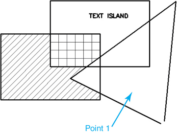
Figure 10-15 The boundary pick point
![]() Set the Gap Tolerance option to 0.25 on the expanded Options panel and pick point 1 again. AutoCAD will display the Open Boundary Warning dialog box so you can select the Continue hatching this area option and create a closed boundary.
Set the Gap Tolerance option to 0.25 on the expanded Options panel and pick point 1 again. AutoCAD will display the Open Boundary Warning dialog box so you can select the Continue hatching this area option and create a closed boundary.
![]() Press <Enter> to accept the hatch pattern and end the HATCH command.
Press <Enter> to accept the hatch pattern and end the HATCH command.
![]() Save your drawing. Your drawing should look like Figure 10-16.
Save your drawing. Your drawing should look like Figure 10-16.
Figure 10-16 The completed hatch
Island Detection. The Island Detection drop-down list allows you to turn island detection on and off and tells AutoCAD how to deal with island areas when placing the hatch. When turned off, AutoCAD will ignore any island areas and create a single boundary around the point you pick.
The Normal option applies the hatch pattern to every other nesting level starting with the outer boundary. The Outer option applies the hatch pattern between the outer boundary and the first nesting level. All further nesting levels are ignored. The Ignore option simply ignores all internal islands and fills the entire outer boundary with the hatch pattern. Figure 10-17 shows the effect of the different Island Detection options.

Figure 10-17 Island Detection options
Note
Text objects (text, Mtext, and dimension text) are treated as though a closed box were drawn around the text. Selecting text inside a closed shape will result in the text being treated as an island within the boundary.
Exercise 10-4 Island Detection
![]() Continue from Exercise 10-3.
Continue from Exercise 10-3.
![]() Start the HATCH command and select the SOLID hatch pattern.
Start the HATCH command and select the SOLID hatch pattern.
![]() Pick point 1 shown in Figure 10-18. AutoCAD will detect the boundary along with the text island.
Pick point 1 shown in Figure 10-18. AutoCAD will detect the boundary along with the text island.

Figure 10-18 The boundary pick point
![]() Select the Ignore Island Detection option on the Options panel. The hatch pattern will now fill over the text island.
Select the Ignore Island Detection option on the Options panel. The hatch pattern will now fill over the text island.
![]() Set the Island Detection back to Normal and press <Enter> to create the hatch pattern and end the HATCH command.
Set the Island Detection back to Normal and press <Enter> to create the hatch pattern and end the HATCH command.
![]() Save your drawing. Your drawing should look like Figure 10-19.
Save your drawing. Your drawing should look like Figure 10-19.
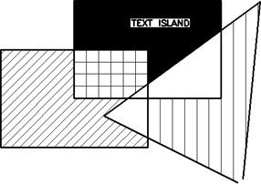
Figure 10-19 The completed hatch
Draw Order. The Draw order setting allows you to control the order in which the hatch pattern is drawn with respect to the boundary. The default option is to send the hatch pattern behind the boundary, which means that the boundary will be drawn on top of the hatch pattern. In most cases, the draw order doesn’t matter; however, in cases where the boundary is on a different layer or is a different color from the hatch pattern, the draw order can affect the look of your drawing.
Matching Existing Hatch Patterns. If you have an existing hatch pattern in your drawing, AutoCAD can read the properties of the hatch pattern and use those settings to create a new hatch pattern. The Match Properties button allows you to select an existing hatch pattern from your drawing and will use the properties of the selected hatch as the default values in the dialog box. When you inherit hatch pattern properties, you have the option of inheriting the hatch origin of the selected hatch pattern or using the currently defined hatch origin. Selecting the down arrow to the right of the Match Properties button allows you to switch from the default Use current origin to the Use source hatch origin option, which will use the hatch origin of the selected hatch pattern.
Exercise 10-5 Inheriting Hatch Patterns
![]() Open drawing EX10-5 located in the student data files. Set the layer Fence current.
Open drawing EX10-5 located in the student data files. Set the layer Fence current.
![]() Start the HATCH command, and choose the Match Properties button on the Options panel. AutoCAD prompts you to Select hatch object:.
Start the HATCH command, and choose the Match Properties button on the Options panel. AutoCAD prompts you to Select hatch object:.
![]() Pick the brick wall pattern on the left side of the drawing. AutoCAD now prompts you to Pick internal point or
Pick the brick wall pattern on the left side of the drawing. AutoCAD now prompts you to Pick internal point or ![]() . Pick the two points shown in Figure 10-20. Press <Enter>. All the settings for the selected hatch are now the default options for your new hatch.
. Pick the two points shown in Figure 10-20. Press <Enter>. All the settings for the selected hatch are now the default options for your new hatch.
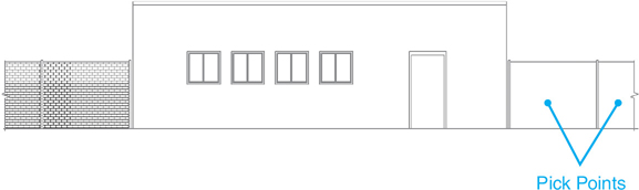
Figure 10-20 The boundary pick points
![]() Press <Enter> to accept the pattern and end the HATCH command.
Press <Enter> to accept the pattern and end the HATCH command.
![]() Save your drawing as CH10_EXERCISE5. Your drawing should look like Figure 10-21.
Save your drawing as CH10_EXERCISE5. Your drawing should look like Figure 10-21.
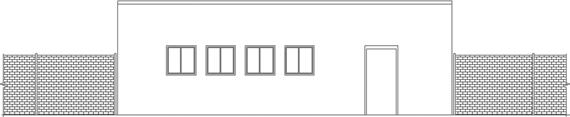
Figure 10-21 Inheriting hatch properties
To access student data files, go to www.pearsondesigncentral.com.
Gradient Fills
In addition to solid fills and hatch patterns, AutoCAD can also create gradient fills. Gradient fills create a smooth color transformation from either one color to light (or dark) or between two selected colors. Gradient fills can be created by selecting the Gradient hatch type from the Properties panel of the Hatch Creation context tab of the ribbon explained earlier or with the GRADIENT command.
The GRADIENT command displays the Hatch Creation context tab of the ribbon with the Gradient options. The Gradient options are similar to a solid hatch fill with two noticeable differences: the number of colors and the gradient pattern.
Gradient |
|
|---|---|
Ribbon & Panel: |
Home | Draw |
Menu: |
Draw | Gradient… |
Command Line: |
GRADIENT |
Command Alias: |
None |
Two-Color Gradient
A two-color gradient fill transitions between the two colors selected for the Gradient Color 1 and Gradient Color 2 options on the Properties panel. When the Two color option is selected, the Gradient Tint and Shade slider bar is disabled. It is the default option.
One-Color Gradient
A one-color gradient fill creates a smooth color transition from a selected color to another shade of that color.
To create a one-color gradient, you must select the Gradient Tint and Shade option on the Properties panel. Selecting this option disables the Gradient Color 2 option and turns on the Gradient Tint and Shade slider on the bottom-right side of the Properties panel. This slider bar controls the shade of the transition color. With the slider at the left-hand side, the transition color is black. With the slider all the way to the right, the transition color is white.
Gradient Pattern
There are nine predefined gradient fill patterns to choose from on the Pattern panel. You choose the pattern you want and then optionally choose a rotation angle. You can also choose to have the fill centered within the boundary or generated from the edge of the boundary by turning on/off the Centered option on the Origin panel. With the Centered option turned off, you can use the Hatch Angle setting on the Properties panel to control which side the pattern generated from. Figure 10-22 shows some combinations of gradient patterns and rotation angles.
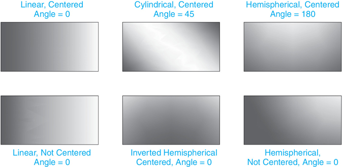
Figure 10-22 Gradient fill patterns
Exercise 10-6 Creating a Gradient Fill
![]() Continue from Exercise 10-5 and set layer Window current.
Continue from Exercise 10-5 and set layer Window current.
![]() Start the GRADIENT command, and pick the points inside the eight window panes shown in Figure 10-23.
Start the GRADIENT command, and pick the points inside the eight window panes shown in Figure 10-23.
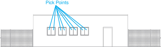
Figure 10-23 The boundary pick points
![]() Select the Gradient Tint and Shade button on the Properties panel. Select the Select Colors… option from the Gradient Color 1 drop-down list, and specify ACI color 142 as the base color for the gradient fill. Choose OK to close the Select Color dialog box.
Select the Gradient Tint and Shade button on the Properties panel. Select the Select Colors… option from the Gradient Color 1 drop-down list, and specify ACI color 142 as the base color for the gradient fill. Choose OK to close the Select Color dialog box.
![]() In the Gradient Tint and Shade slider, move the slider to the right end of the bar, so it is set to 90%.
In the Gradient Tint and Shade slider, move the slider to the right end of the bar, so it is set to 90%.
![]() Select the linear pattern (the first pattern on the left) and set the Angle to 270 on the Properties panel.
Select the linear pattern (the first pattern on the left) and set the Angle to 270 on the Properties panel.
![]() Press <Enter> to accept the pattern and end the GRADIENT command.
Press <Enter> to accept the pattern and end the GRADIENT command.
![]() Save your drawing. Your drawing should look like Figure 10-24.
Save your drawing. Your drawing should look like Figure 10-24.
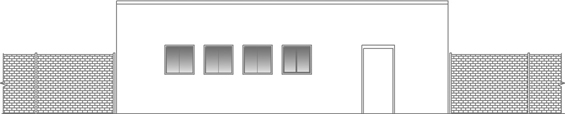
Figure 10-24 A gradient fill
Editing Hatch Patterns
Once a hatch object is created, there are a number of ways to modify it. You can change the hatch pattern along with any of the hatch options. You can even change a hatch pattern to a solid or gradient fill.
EDIT HATCH |
|
|---|---|
Ribbon & Panel: |
Home | Modify |
Menu: |
Modify | Object | Hatch… |
Command Line: |
HATCHEDIT |
Command Alias: |
HE |
Using the Hatch Editor Context Tab of the Ribbon
The easiest way to edit a hatch pattern is to simply select it in your drawing to display the Hatch Editor context tab of the ribbon. The Hatch Editor context tab of the ribbon looks and acts exactly the same as the Hatch Creation context tab of the ribbon explained earlier in this chapter (see Figure 10-2). Any changes you make via the ribbon are applied directly to the selected hatch. Once the hatch pattern looks how you want it, you can either press <Esc> to accept the changes and deselect the hatch pattern or select the Close Hatch Editor button on the Close panel of the ribbon.
Using the Hatch Edit Dialog Box
The HATCHEDIT command allows you to modify any aspect of a hatch pattern using the Hatch Edit dialog box. When you start the HATCHEDIT command, you are asked to select a hatch pattern. Once you select a hatch pattern (or a solid or gradient fill), AutoCAD displays the Hatch Edit dialog box (see Figure 10-25).
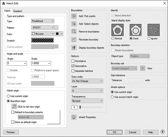
Figure 10-25 The Hatch Edit dialog box
Tip
It is possible to select more than one hatch boundary area at a time in your drawing and update them all simultaneously using the Hatch Editor context tab of the ribbon.
This dialog box is identical to the Hatch and Gradient dialog box used to create hatch objects if you use the seTtings option from the command line. When you select a hatch object, all of that object’s settings are shown as the default values in the Hatch Edit dialog box. From this dialog box, you can change any aspect of the hatch object.
One option that is available in the Hatch Edit dialog box but is not available in the Hatch and Gradient dialog box is the Recreate boundary button. When you select this button, AutoCAD will create a new boundary for the hatch. If the hatch is associative, you have the option of keeping the association with the original boundary or reassociating the hatch with the new boundary. The Recreate boundary button always retains the new boundary as a new drawing object.
Exercise 10-7 Editing Hatch Patterns
![]() Continue from Exercise 10-6.
Continue from Exercise 10-6.
![]() Select the fence hatch pattern on the left side of the building to display the Hatch Editor context tab of the ribbon.
Select the fence hatch pattern on the left side of the building to display the Hatch Editor context tab of the ribbon.
![]() Select the ANSI37 pattern from the Pattern panel and set the Hatch Pattern Scale to 30. Press <Enter> to accept the pattern.
Select the ANSI37 pattern from the Pattern panel and set the Hatch Pattern Scale to 30. Press <Enter> to accept the pattern.
![]() Select the brick pattern on the right side of the drawing to display the Hatch Editor context tab of the ribbon. Choose the Match Properties button and select the ANSI37 pattern you just created.
Select the brick pattern on the right side of the drawing to display the Hatch Editor context tab of the ribbon. Choose the Match Properties button and select the ANSI37 pattern you just created.
![]() Press <Enter> to accept the pattern.
Press <Enter> to accept the pattern.
![]() Save your drawing. Your drawing should look like Figure 10-26.
Save your drawing. Your drawing should look like Figure 10-26.

Figure 10-26 The modified hatch patterns
Using the Properties Palette
The Properties palette is another easy way to make changes to hatch objects. Although you can’t make changes to the hatch boundaries, you can change the hatch pattern, scale, rotation angle, and hatch origin. You can also turn off the associativity and change the island detection method.
Trimming Hatches
When using the TRIM and EXTEND commands, you can select hatch objects as cutting/boundary edges. The edges of the individual hatch pattern lines will be used as stopping points. Only hatch patterns can be used in this manner; gradient and solid fill patterns will be ignored.
When using the TRIM command, you can trim hatch patterns back to selected cutting edges. When trimmed, the boundary edge of the hatch is trimmed back to the cutting edge, and the boundary is recalculated and reassociated if necessary. You cannot extend a hatch pattern out to a boundary edge.
Exercise 10-8 Trimming Hatch Patterns
![]() Continue from Exercise 10-7 and thaw layer Fence2. Two new fence posts are displayed on the left and right sides of the drawing.
Continue from Exercise 10-7 and thaw layer Fence2. Two new fence posts are displayed on the left and right sides of the drawing.
![]() Zoom into the fence post on the left side, and start the TRIM command. Select the new fence post as the cutting edge and press <Enter> to end the edge selection.
Zoom into the fence post on the left side, and start the TRIM command. Select the new fence post as the cutting edge and press <Enter> to end the edge selection.
![]() Pick the fence pattern in the middle of the post to trim the hatch pattern back to the new post. You can also select the boundary line near the top of the fence post to clean up the fence post. Repeat this process on the right-hand fence post.
Pick the fence pattern in the middle of the post to trim the hatch pattern back to the new post. You can also select the boundary line near the top of the fence post to clean up the fence post. Repeat this process on the right-hand fence post.
![]() Save your drawing. Your drawing should resemble Figure 10-27.
Save your drawing. Your drawing should resemble Figure 10-27.

Figure 10-27 Trimming hatch objects
Exploding Hatches
There may be times when you need to modify the individual lines within a hatch pattern. To do this, you can use the EXPLODE command on hatch patterns. The EXPLODE command will convert hatch patterns to individual line segments.
Tip
You must take care when deciding to explode a hatch pattern. Exploding a hatch pattern can create a large number of individual objects and can greatly increase the size of your drawing. You may also have a hard time finding and cleaning up all the little line objects that the EXPLODE command creates.
Using DesignCenter with Hatch Patterns
AutoCAD’s DesignCenter can also be used to create hatch patterns. When using DesignCenter, you can find and select .PAT files on your hard drive or any accessible network drive. When you select a .PAT file, DesignCenter will read the file and display a list of all hatch patterns defined within that file.
To create a hatch object with DesignCenter, you can simply drag and drop the desired hatch pattern into any closed area on your drawing. AutoCAD will create a simple boundary hatch using the default hatch settings. You can then double-click the hatch pattern to display the Hatch Editor context tab of the ribbon and make any desired changes.
Exercise 10-9 Hatching with DesignCenter
![]() Continue from Exercise 10-8 and set layer Elevation current.
Continue from Exercise 10-8 and set layer Elevation current.
![]() Start the ADCENTER command to display the DesignCenter palette. Position the DesignCenter palette at a convenient location on your screen.
Start the ADCENTER command to display the DesignCenter palette. Position the DesignCenter palette at a convenient location on your screen.
![]() In the DesignCenter palette, choose the Folders palette, and navigate to the C:Program FilesAutodeskAutoCAD 2017User Data CacheSupport folder. Double-click on the ACAD.PAT hatch pattern file. After a few moments, DesignCenter will show a list of all the hatch patterns defined in this file.
In the DesignCenter palette, choose the Folders palette, and navigate to the C:Program FilesAutodeskAutoCAD 2017User Data CacheSupport folder. Double-click on the ACAD.PAT hatch pattern file. After a few moments, DesignCenter will show a list of all the hatch patterns defined in this file.
![]() Scroll down the list, and select the AR-BRELM pattern. Drag this hatch pattern onto your drawing, and release it within the boundary of the building wall. AutoCAD will fill the building wall with this pattern. Close or hide the DesignCenter palette.
Scroll down the list, and select the AR-BRELM pattern. Drag this hatch pattern onto your drawing, and release it within the boundary of the building wall. AutoCAD will fill the building wall with this pattern. Close or hide the DesignCenter palette.
![]() Select the pattern you just created to display the Hatch Editor tab of the context ribbon. Change the Hatch Pattern Scale to 2.0, and set the Island Detection to Outer Island Detection on the Options panel.
Select the pattern you just created to display the Hatch Editor tab of the context ribbon. Change the Hatch Pattern Scale to 2.0, and set the Island Detection to Outer Island Detection on the Options panel.
![]() Press <Enter> to accept the pattern.
Press <Enter> to accept the pattern.
![]() Save your drawing. Your drawing should resemble Figure 10-28.
Save your drawing. Your drawing should resemble Figure 10-28.

Figure 10-28 Hatching with DesignCenter
Chapter Summary
Creating hatch and fill patterns is an integral part of drafting and design. Not only do hatch patterns make a drawing look better; they also can provide needed clarity and even indicate the type of material something is constructed of.
AutoCAD makes the process of hatching simple by allowing you simply to pick a point within the enclosed area you wish to hatch. AutoCAD calculates the hatch boundary area by casting a net outward to find the enclosed area and automatically displays the Hatch Creation context tab of the ribbon so you can select one of the many industry-standard patterns that come with AutoCAD or create your own user-defined pattern. Different properties such as color, angle, and scale can then be adjusted as necessary.
Solid fills and gradient fills allow you to apply different effects that can be used to create striking presentation drawings. Using two-color gradient fills, you can apply different shading techniques that represent spheres, cylinders, and boxes. If necessary, you can move the filled areas behind or in front of other objects in the drawing, thereby creating different overlap scenarios.
The best part is that hatch patterns remain associated with their boundary area by default, so if the boundary area changes, the hatch pattern is updated automatically to fill the new area. In addition, selecting an existing hatch pattern automatically displays the Hatch Editor context tab of the ribbon so you can make changes to the hatch pattern, including the pattern type, rotation, scale, and any other property.
The DesignCenter tool, which is typically used to insert blocks and symbols, can also be used to insert hatch patterns using drag and drop. Simply locate any valid AutoCAD hatch pattern definition file with a .PAT extension via the Explorer navigation pane in DesignCenter, and open it. All of the hatch patterns in the file will be listed in the Contents pane on the right, so you can drag and drop them into a valid closed boundary area in your drawing and voilà!
Chapter Test Questions
Multiple Choice
Circle the correct answer.
1. A hatch boundary:
a. Must consist of drawing objects connected end to end
b. Cannot contain any islands
c. Can consist of only straight line segments; curved boundaries are not allowed
d. None of the above
2. The Island Detection option:
a. Controls how island areas are hatched
b. Allows you to ignore all island areas
c. Allows you to hatch every other nested island area
d. All of the above
3. A solid fill pattern:
a. Can use only ACI color numbers
b. Does not work with Color Book defined colors
c. Can use any valid AutoCAD color
d. Can use only RGB or HLS defined colors
4. The boundary set is:
a. The set of objects used when detecting boundary edges
b. The boundary edge of a hatched area
c. Created when associative hatching is turned on
d. None of the above
5. The HATCHEDIT command:
a. Is used to explode hatch objects
b. Is used to modify hatch patterns
c. Does not work on gradient fills
d. All of the above
6. If a predefined hatch pattern is defined as a set of parallel lines .5 unit apart at a 45° angle, applying a hatch scale of 2 and a hatch angle of 180° will result in an area hatch consisting of lines:
a. 2 units apart at an angle of 45°
b. 1 unit apart at an angle of 225°
c. .5 unit apart at an angle of 180°
d. 2 units apart at an angle of 180°
7. A one-color gradient fill transitions only between:
a. Black and white
b. A selected color and white
c. A selected color and black
d. None of the above
8. Hatch patterns can be:
a. Exploded
b. Used as edges in the TRIM and EXTEND commands
c. Modified with the TRIM command
d. All of the above
Matching
Write the number of the correct answer on the line.
a. Hatching ______ |
1. A file that contains hatch pattern definitions, |
b. Gradient fill ______ |
2. A link between two drawing objects so that when one changes, the other updates |
c. Hatch boundary ______ |
3. A solid pattern with a smooth transition from one color to another |
d. Associativity ______ |
4. The allowable open area allowed when detecting boundary edges |
e. Hatch islands ______ |
5. Closed areas within a hatch boundary |
f. Gap tolerance ______ |
6. The process of filling in a closed area with a pattern |
g. Boundary set ______ |
7. The set of objects used when detecting boundary edges |
h. Hatch pattern ______ |
8. The edges of a hatched area |
i. ACAD.PAT ______ |
9. The pattern used to fill a hatched area |
True or False
Circle the correct answer.
1. True or False: Hatch objects cannot be modified. You must delete and re-create them.
2. True or False: DesignCenter can be used to create hatch objects.
3. True or False: Objects must touch end to end to be used as hatch boundaries.
4. True or False: User-defined hatch patterns are always drawn with a continuous linetype.
5. True or False: Text objects are treated as closed objects when determining a boundary.
6. True or False: You can create only one hatch pattern at a time with the HATCH command.
7. True or False: Hatch patterns are defined in .PAT files.
8. True or False: You cannot modify hatch pattern definitions.
9. True or False: Modifying hatch boundary objects can result in losing associativity with their hatch patterns.
10. True or False: AutoCAD can create one-, two-, and three-color gradient fills.
Chapter Projects
 Project 10-1: Calculator, continued from Chapter 5 [BASIC]
Open drawing P5-1 from Chapter 5.
Create the solid and gradient fill areas shown in Figure 10-29. Experiment with different gradient settings to achieve the desired effect.

Figure 10-29
Save your drawing as P10-1.
 Project 10-2: Logo, continued from Chapter 9 [INTERMEDIATE]
Open drawing P9-2 from Chapter 9.
Create the solid fill areas shown in Figure 10-30.

Figure 10-30
Save your drawing as P10-2.
 Project 10-3: Architectural D-Size Border, continued from Chapter 9 [ADVANCED]
Open the template file Architectural D-Size.DWT from Project 9-3 in Chapter 9.
Hatch the logo outline as shown in Figure 10-31 using a two-color gradient hatch on the layer A-Anno-Ttlb-Logo.
Hatch the graphic scale outline as shown in Figure 10-31 using the SOLID hatch on the layer A-Anno-Ttlb-Text.
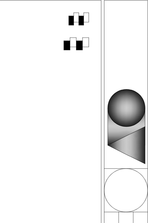
Figure 10-31
Save the drawing to a template file as Architectural D-Size.DWT.
 Project 10-4: Electrical Distribution Panel, continued from Chapter 7 [BASIC]
Open drawing P7-4 from Chapter 7.
Add the hatching shown in Figure 10-32. Make sure the hatching is placed in back of the outlines.
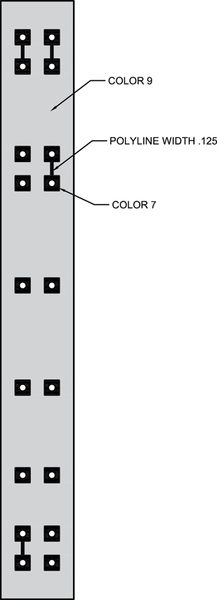
Figure 10-32
Save your drawing as P10-4.
Project 10-5: Residential Architectural Plan, continued from Chapter 9 [ADVANCED]
Open drawing P9-5 from Chapter 9.
Hatch the patio and driveway as shown in Figure 10-33. Use the GRAVEL hatch pattern. Experiment with the scale and rotation angle to achieve the desired stone pattern.
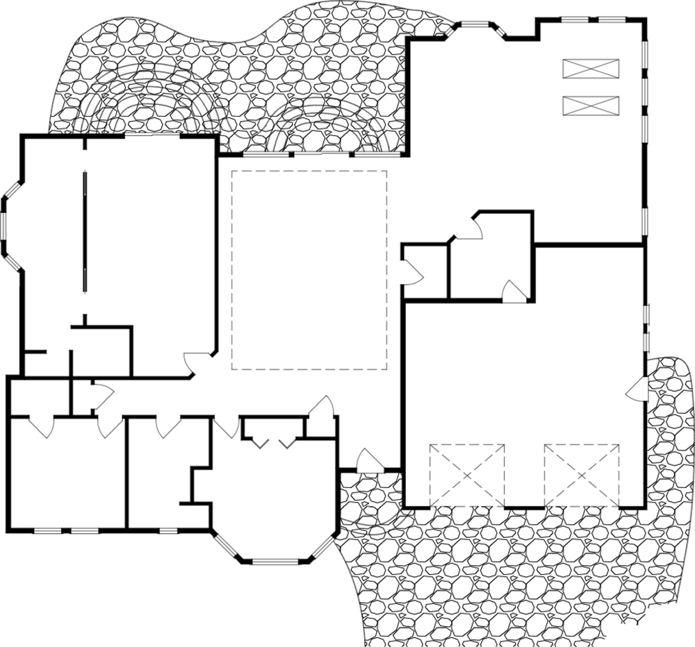
Figure 10-33
Create the solid fill areas in the walls.
Use appropriate layers for all objects.
Save your drawing as P10-5.