
Generic Systemic and Software Architectures for Mobile Robot Intelligent Control
This chapter is concerned with systemic and software architectures that can be used for integrating controllers and high-level functional units to achieve overall intelligent performance of a mobile robot. Software architectures help to deal with the high degree of heterogeneity among the subsystems involved, to face strict operational constraints posed by real-time interactions with the robot’s environment, and to treat the system’s complexity that goes beyond the capabilities of a single designer.
The purpose of this chapter is to provide a tour to fundamental concepts and architectures that integrate low-, medium-, and high-level control and planning functions of mobile robotic systems. Specifically, the following issues are considered: (i) hierarchical, multiresolutional, reference model, and behavior-based system control architectures; (ii) basic characteristics of software architectures; (iii) two examples of robot software control architectures; (iv) comparative evaluation of two software architectures; (v) intelligent human–robot interfaces; (vi) two intelligent mobile robot research prototypes (SENARIO, ROMAN); (vii) design for heterogeneity and modularity.
Keywords
Intelligent control architecture (ICA); hierarchical ICA; multiresolutional ICA; reference model ICA; behavior-based ICA; mobile robot control software architecture; Jde component-oriented architecture; layered mobile robot control software architecture; BERRA; Saphira architecture; WMR software control architecture characteristics; intelligent human–robot interface (HRI); HRI function; intelligent WMR prototype; graphical HRI; SENARIO intelligent wheelchair; semi-autonomous mode; fully autonomous mode; ROMAN intelligent mobile manipulator; multimodel HRI; design for heterogeneity; modular design
14.1 Introduction
In this book we have studied several controllers of mobile robots, and provided a set of fundamental issues regarding the high-level functions of path/motion planning, task planning, localization, and mapping. In Chapter 13, we have presented a host of experimental results (most of which are simulation results) of the above methods and controllers. In this chapter, we will be concerned with systemic and software architectures which can be used for integrating controllers and high-level functional units to achieve overall intelligent performance of a mobile robot. Software architectures help to deal with the high degree of heterogeneity among the subsystems involved, to face strict operational requirements posed by real-time interactions with the robot’s environment, and to treat the system’s complexity that goes beyond the capabilities of a single designer. In general, robot software is the coded commands that tell the robot what functions to perform in order to carry out and control its actions. Actually, the development of robot software is a nontrivial task. Many software frameworks and systems have been developed to make robot programming easier, to achieve a proper run-time for fault tolerant execution, and to obtain systems that are portable to other robotic applications.
Unfortunately, there is no widely accepted software standard for developing mobile robot applications. Robot companies provide their own development frameworks such as ERSP from Evolution Robotics, Open-R from Sony, ARIA from ActivMedia, and Saphira from SRI International. On the other hand, university research groups have developed particular software platforms such as:
The purpose of this chapter is to provide an overview of fundamental concepts and architectures that integrate low-, medium-, and high-level control and planning functions of mobile robotic systems. Specifically, the following issues are considered:
• Hierarchical, multiresolutional, reference model, and behavior-based intelligent control system architectures
• Basic characteristics of mobile robot control software architectures
• Two examples of mobile robot control software architectures
• Comparative evaluation of two mobile robot control software architectures
• Intelligent human–robot interfaces
• Two integrated intelligent mobile robot research prototypes
14.2 Generic Intelligent Control Architectures
14.2.1 General Issues
Intelligent control (IC) has an age of over 40 years and constitutes a generalization of traditional control of the 1940s and 1950s and modern control of the 1960s and 1970s to incorporate autonomous human-like interactive behavior of the controller with the environment. The term “intelligent control” was coined by Fu [6] to embrace the area beyond adaptive and learning control, and according to Saridis [7,8] represents the field which merges control, artificial intelligence (AI), and operational research (OR).
Intelligent control provides the means to achieve autonomous behavior such as planning at different levels of detail, imitation of human behavior, learning from past experience, integration and fusion of sensor information, identification of abrupt changes in system operation, and proper interaction with a changing environment [9].
The field of intelligent control started with the development of generic IC architectures (ICAs), which are mainly the following:
• Multiresolutional/nested ICA (Meystel)
• Behavior-based ICAs, namely, subsumption ICA (Brooks) and motor schemas ICA (Arkin)
These architectures were expanded, enriched, or combined over the years in several ways [10,11]. In the following, we give a brief overview of these architectures in their original abstract form. Most of the software systems and integrated hardware–software systems developed for intelligent mobile robot control follow in one or the other way one of these generic architectures or suitable combinations of them. This will be clear from the discussions of Sections 14.4, 14.5, and 14.7.
14.2.2 Hierarchical Intelligent Control Architecture
This architecture has three main levels, namely (Figure 14.1):

These levels may involve several layers within them that follow the human control mode of interaction between a director (supervisor) with his subordinate employees [7,8].
The organization level implements the higher level functions (e.g., learning, decision making) which imitate functions of human performance and can normally be represented and treaded by artificial intelligence techniques. This level receives and interprets feedback information from the lower levels, defines the planning/sequencing and decision making strategies to be executed in real time, and processes large amounts of knowledge/information with little or no precision. Here, long-term memory exchange is taking place.
The coordination level consists of several coordinators (each implemented by a piece of S/W or a dedicated microprocessor) which receive the task(s) from the organization level. All necessary details must be provided so that the chosen task’s plan is successfully executed.
The execution level involves the actuators, the hardware controllers, and the sensing devices (visual, sonar, etc.) and executes the action programs issued by the coordination level.
Saridis has developed a complete analytic theory for this architecture, formulating and exploiting the Principle of Increasing Precision with Decreasing Intelligence using the information entropy concept. Neural networks, fuzzy systems, Petri nets, and optimal control have been used in these hierarchical levels [12].
14.2.3 Multiresolutional Intelligent Control Architecture
This architecture was developed by Meystel [13–15] and first applied to intelligent mobile robots. It follows the commonsense model Planner-Navigator-Pilot-Execution Controller. The Planner delivers a rough plan. The Navigator computes a more precise trajectory of the motion to be executed. The Pilot develops online tracking open-loop control. Finally, the Execution Controller executes plans and compensations computed by the planner, the navigator, and the pilot. This scheme is implemented in the form of the so-called multiresolution six-box (Figure 14.2A). Each level contains perception (P), knowledge representation, interpretation and processing (K), and planning and control (P/C) operations which are shown in more detail in Figure 14.2B.
Figure 14.2 (A) Three-level multiresolution architecture (6-box-representation). (B) Each level has its own feedback loop.
In Figure 14.2B, A is a source and a storage of the world model, B is a computer controller which processes the sensor data and computes the control commands required to achieve the system’s goal, and C is the machine that performs the process of interest with actuators that transform control commands into actions, and with sensors that inform the computer controller about the process.
The fundamental properties of the multiresolutional ICA are the following:
P1: Computational independence of the resolutional levels.
P2: Each resolution level represents a different domain of the overall system.
P3: Different resolution levels deal with different frequency bands within the overall system.
P4: Loops at different levels are six-box diagrams nested in each other.
P5: The upper and lower parts of the loop correspond to each other.
P6: The system behavior is the result of superposition of the behaviors generated by the actions at each resolution level.
P7: The algorithms of behavior generation are similar at all levels.
P8: The hierarchy of representation evolves from linguistic at the top to analytical at the bottom.
P9: The subsystems of the representation are relatively independent.
14.2.4 Reference Model Intelligent Control Architecture
This architecture (RMA) was developed and expanded at the National Institute of Standards (NIST) by Albus and colleagues [16–18]. It is suitable for modular expansion (Figure 14.3).
The control problem in the reference model ICA is decomposed in the following subproblems:
The various control elements are clustered into computational nodes arranged in hierarchical layers, each one of which has a particular function and a specific timing behavior. The NIST paradigm has been refined many times. Starting with the cerebellar model in the 1970s, it was evolved to the RCS-4 (Real-time Control System-4) in the 1990s and was applied to automated manufacturing systems, army field material handling systems, multiple underwater mobile robots, and telerobotic service systems. The main design issues addressed by RMA are the following:
14.2.5 Behavior-Based Intelligent Control Architectures
These architectures are based on the concept of agent and can be implemented using knowledge-based systems, neural, fuzzy or neurofuzzy structures [14–19]. The two most common behavior-based architectures are the subsumption architecture developed by Brooks [20,21] and the motor schema architecture developed by Arkin [22–24]. The subsumption architecture follows the decomposition of the behavior paradigm (Figure 14.4B) and was first employed in the autonomous mobile robot Shakey.
Figure 14.4 Distinction between the classical sense-plan-act model (A) and the subsumption model (B).
The tasks, achieving behavior, are represented as separate layers. Individual layers work on individual goals concurrently and asynchronously. At the lowest level, the system behavior is represented by an augmented finite state machine (AFSM) shown in Figure 14.5.

The term “subsumption” originates from the verb “to subsume” which means to think about an object as taking part of a group. In the context of behavioral robotics, the term subsumption comes from the coordination process used, between the layered behaviors within the architecture. Complex actions subsume simple behaviors. Each AFSM performs an action and is responsible for its own perception of the world [15,16].The reactions are organized in a hierarchy of levels where each level corresponds to a set of possible behaviors. Under the influence of an internal or external stimulation, a particular behavior is required. Then, it emits an influx toward the inferior level. At this level, another behavior arises as a result of simultaneous action of the influx and other stimuli. The process continues until terminal behaviors are activated. A priority hierarchy fixes the topology. The lower levels in the architecture have no awareness of higher levels. This allows the use of incremental design. That is, higher level competencies are added on top of an already working control system without any modification of those lower levels.
The motor schemas architecture was more strongly motivated by biological sciences and uses the theory of schemas, the origin of which goes back to the eighteenth century (Immanuel Kant). Schemas represent a means by which understanding is able to categorize sensory perception in the process of realizing knowledge of experience. The first applications of schema theory include an effort to explain postural control mechanisms in humans, a mechanism for expressing models of memory and learning, a cognitive model of interaction between motor behaviors in the form of schemas interlocking with perception in the context of the perceptual cycle, and a means for cooperation and competition between behaviors.
From among the various definitions of the schema concept available in the literature, we give here the following representative ones [17,18]:
• A pattern of action or a pattern for action
• An adaptive controller which is based on an identification procedure for updating the representation of the object under control
• A perceptual entity corresponding to a mental entity
• A functional unit that receives special information, anticipates a possible perceptual content, and matches itself to the perceived information
A convenient working definition is the following [19]: “A schema is the fundamental entity of behavior from which complex actions can be constructed, and which consists of the knowledge how to act or perceive, as well as the computational process by which it is enacted.”
Using schemas, robot behavior can be encoded at a coarser granularity than neural networks while maintaining the features of concurrent cooperative–competitive control involved in neuroscientific models. More specifically, schema theory-based analysis and design of behavior-based systems possesses the following capabilities:
• It can explain motor behavior in terms of the concurrent control of several different activities.
• It can store both how to react and how to realize this reaction.
• It can be used as a distributed model of computation.
• It provides a language for connecting action and perception.
• It provides a learning approach via schema elicitation and schema tuning.
• It can explain the intelligence functions of robotic systems.
Motor schema behaviors are relatively large grain abstractions, which can be used in a wide class of cases. Typically, these behaviors have internal parameters which offer extra flexibility in their use. Associated with each motor schema there is an embedded perceptual schema which gives the world specific for that particular behavior and is capable of providing suitable stimuli.
Three ways in which planning (deliberative) and reactive behavior can be merged are [24] as follows:
• Hierarchical integration of planning and reaction (Figure 14.6A)
• Planning to guide reaction, that is, permitting planning to select and set parameters for the reactive control (Figure 14.6B)
• Coupled planning–reacting, where these two concurrent activities, each guides the other (Figure 14.6C)
One of the first robotic control schemes that were designed using the hybrid deliberative (hierarchical) and reactive (schema-based) is the autonomous robot architecture (AuRA) [24]. AuRA incorporated a traditional planner that could reason over a modular and flexible behavior-based control system (Figure 14.7).
14.3 Design Characteristics of Mobile Robot Control Software Architectures
To design or evaluate a robot control software architecture, the following desirable key characteristics should be considered [25]:
A brief description of each of them is as follows.
Robot hardware abstraction: A primary design goal of hardware design is portability because robot hardware is generally changing. Abstraction of hardware such as actuators and sensors must be accommodated in a portable architecture. Typically, the hardware provided by manufacturers involve hardware-specific commands (such as to move in absolute or velocity mode) which are encapsulated into a generalized set of commands. It is highly desirable to keep the hardware characteristics in a single file of the software source. This file must be the only place where changes have to be performed when moving the system to a new hardware.
Extendibility–scalability: Extendibility is the capability to add new software components and new hardware modules to the system. This is a very important characteristic since robotic systems in research and development environments evolved in terms of both hardware and software. For example, the addition of new sensors is a typical process in these environments. Scalability can be achieved using dynamic objects and process invocation on a live-when-needed basis. Modern software tools have factory patterns that help in this.
Reusability: Reusing existing knowledge from previous designs can speed up the mobile robot software development. A popular approach to this is through software reuse of components, structure, framework, and software patterns [26,27]. Software patterns are classified according to three software development levels, namely, analysis or conceptual patterns for the analysis level, design patterns for the design level, and programming patterns for the implementation level.
Repeatability: Repeatability means that running the same program on the same input gives the same result. For typical single-threaded programs, repeatability is a must for functional correctness. For real-time distributed systems, repeatability is not necessary for correctness. A simple form of repeatability allows the developer to debug an individual task by rerunning it on logged data, presenting logged messages to a task in the same order in which they were received.
Run-time overhead: When a program is running (executing), we say that it is in run-time. The term run-time is used by a computer language to manage a program written in the language. A run-time error is an error that occurs while the program is executing. Run-time overhead is specified by several issues, such as memory requirements, CPU requirements, frequency, and end-to-end latency.
Software features: A mobile robotic control system must be reliable and robust to unexpected events. The framework for robust integration should integrate all skills. For research and development purposes, software architecture, besides reusability and repeatability, should provide the means for the following:
For a general software system, the following features are important:
• Design simplicity (in both the implementation and interface)
• Design correctness (in all aspects)
• Design consistency (i.e., absence of inconsistencies)
• Design completeness (i.e., coverage of as many important aspects as it is practical)
A good architecture must be based on a formal theory which is adhered by the software developers.
Tools and methods: Today, several tools for constructing software architectures, standardized by international bodies (ISO, ANSI, OMG, etc.), are available. The hardware providers offer the basic interface for evaluating the hardware. This may be a C language API. Early software systems for mobile robots were almost exclusively programmed in C. Artificial intelligence workers were using LISP. Now, we use popular OO-based languages such as C++ and Java or the component technology CORBA (common object request broker architecture). Very popular are also the LabVIEW (laboratory virtual instrumentation engineering workbench) of national instruments (NI), and the UML (unified modeling language) which is supported by tools that allow the automatic synthesis, analysis, and code generation.
A key component in a robotic system is a reliable and efficient communication mechanism for exchanging and transmitting data and events. Data transfer can be initiated in either a pull or a push way. The interaction of tools such as CORBA, Microsoft Active X, and enterprise Java beans (EJB) can be achieved through interface description language (IDL).
Documentation: Software architecture should be accompanied with proper and rigorous documentation, which can be used nonlocally, and includes the following:
Obviously, the philosophy of an architecture remains the same throughout, but the other elements of documentation should be refreshed to reflect any changes or improvements performed over the time. Documentation can be made in the following ways:
A combination of them is very useful and desirable. Today, there are available JavaDoc/Doxygen utilities that are embedded in the code.
14.4 Brief Description of Two Mobile Robot Control Software Architectures
14.4.1 The Jde Component-Oriented Architecture
The Jde architecture uses schemas which are combined in dynamic hierarchies to unfold the global behavior [28,29]. Each schema is built separately into a plug-in and linked to the framework dynamically when required. The Jde software architecture follows the hierarchical scheme shown in Figure 14.6A, that is, it combines deliberation and reactiveness in a proper and successful way. Each schema is a task-oriented piece of software which is executed independently. At any time, there may be in execution several schemas, each one designed to achieve a goal or complete a particular task. In Jde, a schema:
• is tunable (i.e., it can modulate its behavior accepting continuously some parameters);
• is an iterative process (i.e., it performs its work via periodical iterations giving an output when each iteration is finished);
In Jde, hierarchy is considered as a co-activation that only means predisposition. A parent can coactivate several children at the same time, but this does not mean that all children gain control of the robot. The children’s real activation is determined by an action–selection mechanism that continuously selects which one gets the control at each iteration, given the current goal and environment condition. Three advantages of this hierarchical scheme are reduced complexity for action–selection, action–perception coupling, and distributed monitoring. A motor schema may control the actuators directly or may awake a set of new child schemas. The sequence of activations creates a specific hierarchy of schemas for producing a particular global behavior (Figure 14.8) [28]. All awake schemas (checking, ready, winner) run concurrently. Hierarchies are specific to each global behavior. Once the parent has awaked its children schemas, it continues executing and checking its own preconditions, monitoring the actions of its children, and modulating them appropriately. All the active schemas, except the winner one, are deactivated, and a new tree is generated under the new winner.
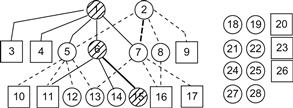
Figure 14.8 Jde hierarchical architecture where there is one winner (denoted in shaded) at each level.
In Figure 14.8, circles represent motor schemas, and squares represent perceptual schemas. The Jde architecture was implemented in the Jdec software platform in the language C. The Jdec platform supports the hardware of Pioneer robot equipped with additional vision sensors. Several schema-based behaviors were constructed, namely, person following, laser-based and vision-based localization, virtual force field-based local navigation, and gradient-based deliberative global navigation. In the hierarchy, each schema provides a set of shared variables for communication with other schemas which is performed by shared memory. When in winner state, a schema specifies and updates continuously its output. Perceptive schemas do not take part in the action–selection process and always gain easily the winner state.
The pseudocode of a Jdec schema is [29]:
Due to the iterative execution style, CPU consumption is moderate and facilitates the design of an application in a reactive fashion. Each schema is written in two separate C files, namely:
They are both compiled jointly in a single C module. All schemas of an application are statically linked together in the executable.
In the enhanced Jde architecture (called Jde-neoc), several new tools were developed and added. These are as follows:
• A visualization tool for the visualization of sensors, actuators, and other elements
• A management tool which allows the manual activation and deactivation of schemas, as well as their graphical user interface (GUI). This helps very much the debugging of any set of schemas.
In Jde-neoc, the perception and control are distributed among a set of schemas which are software elements, with a clear API each built as a plug-in on a separate file. Details on the design and implementation of Jde and Jde-neoc can be found in Refs. [28,29].
14.4.2 Layered Mobile Robot Control Software Architecture
This is simple software architecture of the type shown in Figure 14.1, which involves three or four hierarchical layers, each of which depends only on the specific hardware platform used, and is not informed on the contents of layer above or below it [30]. This layered architecture is depicted in Figure 14.9 for a mobile robot or manipulator, which includes all necessary high-level and low-level functions from task definition, path planning, and sensor fusion to sensor/actuator interfacing and motor control.
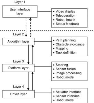
For fully autonomous operation, the layers 2 through 4 are needed; the layer 1 is not always required.
This software architecture was designed and developed for implementation on the NI CompactRIO platform for robotics combined with the LabVIEW graphical development environment.
LabVIEW is typically used for data acquisition, instrument control, and industrial automation on a variety of platforms including Microsoft Windows, and several versions of UNIX, Linux, and MacOS [31]. The programming language used in LabVIEW is called G, and is a data flow programming language. The execution sequence of the LabVIEW graphical syntax is as well defined as with any textually coded language (C, Visual BASIC, etc.). LabVIEW embeds into the development cycle, the construction of user interfaces (called “front panels”). LabVIEW programs and subroutines are called virtual instruments (VIs), each one of which has three elements (block diagram, front panel, connector panel). The front panel exhibits controls and indicators that allow a user to input data into or extract data from a running VI. In addition, the front panel can also act as a programming interface. A benefit of LabVIEW over other development environments is the extensive support for accessing instrumentation hardware (http://ni.com//labview).
A short description of the functions performed in each layer of the architecture is as follows.
User interface layer: The user interface (UI) allows a human operator to interact physically with the robot via relevant information provided on the host PC. To display live data from an on-board or fixed camera or the xy coordinates of nearby obstacles on a map, a GUI should be employed. This layer can also be used for reading input data from a mouse or joystick or to drive a simple display. An emergency (high priority) stop must also be included in this layer.
Algorithm layer: This layer involves the high-level control algorithms of the robot. Its units obtain information (position, speed, video images) and make feedback control decisions for the tasks which the robot has to perform. Here, the components for mapping the robot’s environment and performing obstacle avoiding path/motion planning, as well as for high-level task planning are included.
Platform layer: Here, the code that corresponds to the physical hardware configuration is contained. Actually, it can be used as a translator between the driver layer and algorithm layer. This layer converts low-level information (from the sensors’ interface and actuators’ interface) to a more complete form to be sent at the algorithm layer, and vice versa.
Driver layer: Here, the low-level driver functions needed to move the robot are generated, depending on the sensors and actuators used and the hardware in which the driver software runs. The actuator set points (for position, velocity, torque, etc.) are received by the driver layer in engineering units and converted to low-level signals, potentially including code to close the appropriate loops over those set points. Similarly, the raw sensor data are turned into meaningful units and passed to the other layers of the architecture. The driver level can be implemented in field programmable gate array (FPGA). In the NI architecture, the driver code is implemented in LabVIEW FPGA and executes on an embedded FPGA on an NI CompactRIO platform. The driver can be connected to physical sensors or actuators, or it can interface to simulated input–output data within a simulator of the environment. For research and development purposes, a switch between simulation and actual hardware must be provided, which operates without affecting the other layers. An overall pictorial representation of the above mobile robot reference control software architecture overlayed on an NI CompactRIO or NI Single-Board RIO embedded system is shown in Figure 14.10 [30].

Figure 14.10 Mobile robot reference control software architecture overlayed onto an embedded real-time processor and FPGA.
The above architecture is similar to that used in the NASA mobile manipulators designed by “Superdroid Robots” (see Figure 1.30) (http://superdroid.com/#customized-robots-and-robot-parts).
14.5 Comparative Evaluation of Two Mobile Robot Control Software Architectures
14.5.1 Preliminary Issues
Here, a comparative evaluation of two mobile robot control software systems drawn from Ref. [25] will be summarized. The two systems evaluated are the Saphira architecture, which was developed at SRI International Artificial Center [32], and behavior-based robot research architecture (BERRA) [33].
Saphira architecture was developed to exert intelligent control to the Flakey mobile robot [34] following the perception–action cycle scheme. The software runs a fuzzy logic-based reactive planning and a behavior sequencer. The system includes integrated modules for sonar sensor interpretation, mapping, and navigation. The core of the system consists of a server that manages the hardware, and Saphira software as a client to this server. The Saphira architecture is depicted in Figure 14.11A and B [32].

Saphira and user routines in Figure 14.11A are all microtasks that are invoked during every synchronous cycle (100 ms) by built-in microtasking operating system. These routines realize packet communication with the robot, create the robot’s state picture, and carry out more complex tasks such as sensor interpretation and navigation. The internal State Reflector helps to avoid the tedious task of control programs to deal with packet communication issues, reflecting well the robot’s state on the host computer. The robot server can handle up to 10 routines or more per 100 ms cycle. Additional user routines on the left subsystem of Figure 14.11A can be executed asynchronously as separate threads sharing the same address space.
As shown in Figure 14.11B, the control architecture is built on the top of the state reflector, and consists of a set of microtasks/asynchronous tasks that implement all navigation functions, interpreting the sensor readings about a geometric world model, and mapping the robot states to control functions.
Localization is performed using Markov-type routines that connect the robot’s local sensor readings to its map of the world. The multirobot interface links the robot to other robots via TCP/IP connections [35]. The path planning is performed combining the two available geometric representations for local path planning (local perceptual space, LPS) and global path planning (global map space, GMS).
BERRA was developed with primary design goals the flexibility and scalability. It was implemented using the adaptive communication environment (ACE) package [36]. The use of ACE allows the portability of the system across a large class of operating systems and provides powerful means for server/client interaction and service functioning.
The evaluation presented in Ref. [25] was carried out using a test-case service agent, where the operator could command the robot to navigate in an office environment for which a map was known a priori. The two architectures were ported to the Nomadic Super Scout robot shown in Figure 14.12.
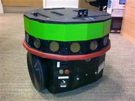
Figure 14.12 The Nomadics super scout mobile robot. Source: http://ubirobot.ucd.ie/content/nomad-scout-2-and-nomad-super-scout.
This is a small robot having 16 ultrasonic sensors (Polaroid) and 6 tactile sensors. A serial port is used for the communication of the motherboard and the controller board. The Scout robot is equipped with the Red Hat Linux operating system and a C language API.
14.5.2 The Comparative Evaluation
14.5.2.1 Operating System and Language Support
Saphira: Most operating systems are supported (UNIX, MS Windows, etc.). The GUI is based on Motif. The core of the system is programmed in C. It has a C-like syntax with finite state machine-based semantics, and part of Saphira is written in LISP.
BERRA: Linux and Solaris Operating Systems and all ACE platforms are supported. The Esmeralda speech recognition system is used [37], and vision functions employ Blitz++ [38].
14.5.2.2 Communication Facilities
Only BERRA is of the multiprocess communication. BERRA uses sockets based on ACE, and support UNIX and INET socket protocols.
14.5.2.3 Hardware Abstraction
In Saphira, hardware abstraction is performed in the robot server (i.e., there is only one abstraction level). Client processes cannot address the lower level hardware. BERRA also has one high-level abstraction, but control of lower level hardware can be achieved by parameterizing the high-level commands using a difficult syntax.
14.5.2.4 Porting and Application Building
Saphira porting of the hardware level code needs major effort. In the study described in Ref. [20], only the source code of the Pioneer platform server was available (actually a number of C files with no clear interdependencies). All relevant behaviors were provided with the system, and the construction of the map and its incorporation into the LPS was easy. So, localization performed well out of the box. Originally, BERRA ran on Nomad 2000 and Nomad 4000. Although the hardware of them can accept calls from multiple clients, the Scout can only be accessed by one client and created a problem for BERRA. A newer version of BERRA allowed only one of its processes to access and control the robot hardware.
14.5.2.5 Run-Time Consideration
Saphira can be easily started by first starting the robot server and then Saphira which then is connected to the server. Then, behaviors and tasks can be directly started and stopped by the operator in the GUI with the Colbert interpreter. Libraries can be dynamically loaded in run-time. Using GUI the robot’s position in the map of the environment can be updated. In Saphira, 10 MB of memory is sufficient, but the response time (~0.6 s) is high. The major drawback of Saphira is the inaccuracy of the localization system (position track is lost after approximately 10 m).
BERRA can be started by a shell-script as long as everything goes as planned. If for any reason a process goes wrong, the system needs to be totally restarted. The time needed from a sensor reading to a corresponding actuator control signal is very low (about 0.17 s). BERRA needs 36 MB of run-time memory, but does not have a GUI. In the tests, BERRA performed very well (the scout could traverse a department for hours according to navigation requests).
14.5.2.6 Documentation
Saphira is very well documented and supported by many publications and a complete manual that includes a user’s guide. But the code is not so well documented. BERRA is supported by many publications and a web-based documentation. Users and programmers have at their disposal short guides.
Details of the evaluation together with problems that must be avoided, and guidelines on how to choose among available commercial or research mobile robot platforms in order to meet specific goals and requirements can be found in Ref. [25]. A survey of nine open sources, freely available, robotic development environments (RDEs) is provided in Ref. [39]. This survey compares and evaluates these RDEs by establishing and using a comprehensive list of evaluation criteria, which includes the criteria presented in Section 14.3. First, a conceptual framework of four broad categories is presented based on the characteristics and capabilities of RDEs. The evaluation and comparison of these nine RDEs conclude with guidelines on how to use profitably its results. A comprehensive book dedicated to software architecture with deep and illuminated design issues is Ref. [40].
14.6 Intelligent Human–Robot Interfaces
14.6.1 Structure of an Intelligent Human–Robot Interface
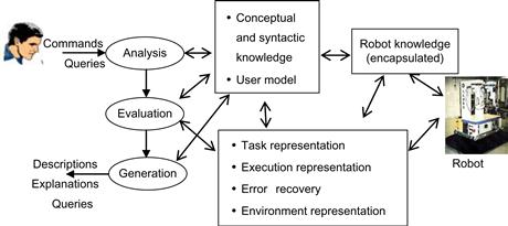
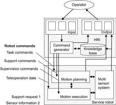
Interfaces play a key role for the successful and efficient operation of an intelligent robot such that to fulfill its goals with the aid of multisensors and shared autonomy [41]. Here, the basic design principles of intelligent human–robot interfaces (HRIs) will be outlined. An intelligent HRI has the general self-explained structure shown in Figure 14.13.

The robotic system involves a supervisor, a planner, and a controller, and sometimes, if required, a decision support component which contributes to the realization of cooperative human–robot decision making and control.
The three main types of users are operators, engineers, and maintenance specialists. These users interact with the robotic system via the HRI. Users have in general different but overlapping needs with respect to depth and quantity.
14.6.2 Principal Functions of Robotic HRIs
The principal functions of HRIs are the following [42]:
The input handling function provides the means to utilize the type of inputs received by the system which may be analog, digital, probabilistic, linguistic, and fuzzy.
The perception and action function is fundamental for the overall HRI performance and is supported by the presentation level of the HRI which determines how to present the information to the user and how to transform his/her control inputs.
Dialogue handling (control) undertakes the task of determining what information to treat and when. A dialogue is any logically coherent sequence of actions and reactions exchanged between the user and the HRI. Human–machine dialogues are necessary for many robotic operations (e.g., scheduling, supervision, planning, control).
Tracking interaction is concerned with tracking the entire interaction between the HRI and the human user, as well as between the HRI and the robotic system at hand.
The explanation function needs a model of the robotic system to be available. Its role is to explain to the user the meaning of the various aspects and components of the robotic system, and sometimes of the HRI itself. It should be also capable of explaining how the various parts of the system operate.
Output generation is realized using graphical editors and typically offers appropriate graphical and textual pictures which are dynamically changing. In more recent applications, multimedia presentations are also provided. If the HRI is required to be able to adapt to different users or user classes, a user model is also needed. To design a user model, it is necessary to use our knowledge on human processing behavior and represent the cognitive strategies, via rules, algorithms, and reasoning mechanisms. A more complete user model must also include a model of the robotic system in order to incorporate the user’s view with respect to the robotic system.
14.6.3 Natural Language Human–Robot Interfaces
A special very popular class of HRIs is the class of natural language interfaces (NLIs). NLIs possess humanized properties since the user can communicate with the robot through a kind of verbal language (e.g., a small subset of English). Actually, NLIs are not the best interfaces in all cases. Thus, to decide whether to use a NLI or not, one has to consider several factors, of which some examples are the following:
• Ease of learning: If a full natural language (NL) is used, no human effort is necessary to learn it. This is not so if a restricted language with legal statements is used.
• Conciseness: The desire for conciseness is usually in conflict with the user friendliness.
• Precision: Many English sentences are ambiguous. It is so natural that English does not use parentheses as artificial logical languages do.
• Need for pictures: Words are not the best way to describe shapes, positions, and curves. A picture is worth many words. However, programs that handle graphical objects (e.g., CAD systems) are still good candidates for NLIs and other linguistic interfaces.
• Semantic complexity: NLs are concise and efficient when the universe of possible messages is large. Actually, no trivial language can perform the interfacing job, since the number of different messages that have to be handled is extremely large.
• Cost: The cost of NLIs used is higher than that of standard HRIs.
The components of an NL understanding system, that is, a system that transforms statements from the language in which they were made in a program-specific form that initiates appropriate actions, are as follows:
The above primary components can be merged into an integrated understanding system in the following three ways:
1. Interactive selection: The system displays the options to the user who chooses among them to gradually construct a complete statement, which corresponds to actions that the target program can perform.
2. Semantic grammars: The window-based approach does not allow the user to control interactions or compose free-form statements that the system has to understand. The alternative is for the user to compose entire statements. A semantic grammar provides one implementation of this alternative approach but is appropriate when a relatively small subset of an NL has to be recognized.
3. Syntactic grammars: If a large part of NL is used as HRI, the capture of as much of the language regularity as possible is required. To this end, it is necessary to capture the syntactic regularity of the NL at hand. Thus, one needs to use a syntactically motivated grammar.
In the literature, several tools are described that assist in the building process of the lexicon, the grammar, the semantic rules, and the code that uses all of them. Also, some programs exist that do most of the understanding in all three approaches discussed above.
NLIs in robotics have been considered and used by many researchers, for example:
14.6.4 Graphical Human–Robot Interfaces
Graphical HRIs (GHRIs) represent a very large area of information technology. GHRIs are used for task analysis, online monitoring, and direct control. For example, to teleoperate a mobile robot in a critical workspace, a considerable effort must be devoted to preparing the task, training the operator, and finding the optimal cooperation modes in various situations. Before actually executing a task, a GHRI can help the user to specify his intention, display the commands, and the expected consequences on the monitor. In this way, the user can interactively generate and modify a plan.
On a GHRI, an operator can define a series of movements and actions by clicking or dragging a mouse on the screen. The available task and geometric planners can then find a sequence of motions and actions that implement the task. A simulation system is usually designed and used to animate the robot’s motion on a 2D or 3D workspace, where several viewpoints can be set to monitor and observe the robot’s behavior and its relation to the world. Possible collisions with obstacles, robots, and other objects are avoided. Here, the optimal utilization of various sensors is a fundamental prerequisite. As an additional aid, a task editor is used to support the task specification by interactively modifying a plan. It is useful if with this task editor, the operator can also define a sequence of actions as a macro. The macros can be retrieved and used to represent and implement an entire task plan. A useful concept that can be used in task analysis is the concept of telesensor programming (Hirzinger, [10]). Due to the unavoidable errors in the dead-reckoning and world models, the sensor patterns have to be employed by the robot to ensure an accurate relation with the world.
Graphical interfaces are very often combined with animation and virtual reality (VR) tools. Examples of this type are the works of Heinzmann [46], Rossmann [47], and Wang et.al [48].
In Ref. [46], the HRI of the robot consists of a visual face tracking system. The system employs a monocular camera and a hardware vision system to track several facial features (eyes, eye brows, ears, mouth, etc.). The 3D pose and orientation of the head are computed using this information. The solution to the design of human-friendly robots, provided, satisfies two safety goals.
Safety goal 1: A human-friendly robot should be able to operate without posing a threat when humans are inside the robot’s workspace.
Safety goal 2: In an unstructured environment which may involve humans, any action autonomously taken by the robot must be safe even when the robot’s sensor information about the environment is uncertain or false.
In Ref. [48] the human–machine system includes a virtual tools system, an automatic path planner, and a collision detection simulator. Tests on the performance of the path planner are also discussed. A virtual tools HRI for point specifications of tasks, which interweaves virtual robot end/effector representations with physical reality to immerse the human in the scene using simple hand gestures, needs to be developed for flexibly designating where the robot should grasp as an incoming part. The virtual tools system is displayed in four quadrants on a Silicon Graphics workstation with Galileo video. The virtual gripper is displayed on the two left quadrants display, superimposed on two camera views and blended with live video, to create the illusion of a real gripper in two views in the physical scene. The top right quadrant is occupied by the toolbox of graphic icons representing various tools available for use by the robot. The bottom right quadrant displays homogeneous transformation matrix information such as graphic object models and views from the robot camera. This Pennsylvania University system which is based on the virtual tool concept allows the operator to direct robot tasks in a natural way in almost real-time.
In Ref. [47] a multirobot system (called CIROS) is designed that implements the capability to derive robot operations from tasks performed in the virtual reality environment. To this end, two appropriate components are used: the change-detection component and the change-interpretation component. The VR system employed is based on a special simulation system (COSIMIR, cell-oriented simulation of industrial robots) developed at the Institute of Robotics Research in Dortmund, Germany. In CIROS, a new VR concept is used. This is called projective virtual reality (PVR), because the actions carried out by humans in the VR are projected on to robots to carry out the task in the physical environment. The intelligent controller implements PVR-based control by adding the levels for online collision avoidance, multirobot coordination, and automatic action planning.
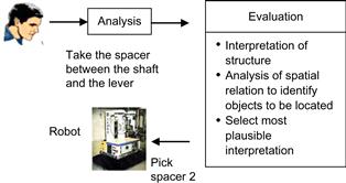
As an example, we describe briefly the NL HRI of the KAMRO intelligent mobile robot, which was designed and built at the University of Karlsrue [49,50], and uses a multiagent architecture.
A fundamental problem in such multiagent system (MAS) is the negotiation among the agents that compete for a given task. This negotiation process can be performed by a centralized mediator or a selected candidate or by many (or all) candidates. All agents should be able to negotiate with the competing agents. One way to manage the communication among agents is via a blackboard system. Possible in a MAS are the following:
These deadlock situations are successfully translated into corresponding mechanisms in the KAMRO robot.
The NL HRI of KAMRO performs the following functions:
• Task specification/representation, that is, analysis of instructions related to the implicit robot operations (e.g., “pick-and-place,” bin picking)
The KAMRO NL HRI architecture is as shown in Figure 14.14.
The robot and the NL HRI have permanent access to the correct environment representation via an overhead camera. This information is stored in a common database. Since the world representation changes over time, a timestamp of the snapshot is used which allows merging older and newer knowledge about the environment. The processing of NL instructions is illustrated in Figure 14.15.
An edited book with outstanding contributions covering a wide repertory of concepts, techniques, and applications of HRIs is Ref. [51].
14.7 Two Intelligent Mobile Robot Research Prototypes
Here, two working research prototypes of integrated mobile robots will be briefly presented. These are the robotic wheelchair SENARIO, developed within the frame of the European Union TIDE project SENARIO: sensor-aided intelligent navigation system for powered wheelchairs1 [52,53], and the ROMAN service MM, designed and built at the Technical University of Munich [54–56].
14.7.1 The SENARIO Intelligent Wheelchair
This intelligent mobile robot system was implemented and tested on a Meyra powered wheelchair as shown in Figure 14.16.
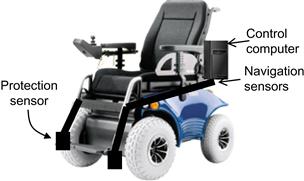
Figure 14.16 The SENARIO wheelchair intelligent mobile robot system was integrated on a commercial MEYRA platform. The components of the system include a computer, an orientation (encoder) sensor, and an ultrasonic sensor array (eight sensors for navigation and three sensors for protection; two in the front and one in the back).
The architecture of the SENARIO mobile robot, which is a virtually centralized hierarchical control architecture, is shown in Figure 14.17. Two functional alternatives are possible in SENARIO:
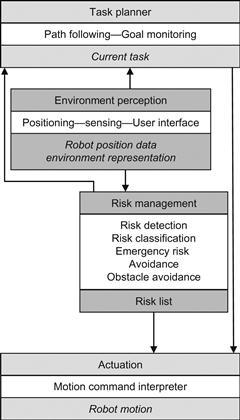
The following four processes determine the autonomous behavior actions of SENARIO (Figure 14.17):
1. Task planning, which schedules the execution of all the other processes and is responsible for overall system control. The planning, path following, and goal monitoring procedures reside in the task planner. Task planning is on the top of the control hierarchy of the robot.
2. Environment perception, where a set of sensors is used to truck the interactions of the robot with its environment. Sensor data processing, environment features extraction, and positioning, as well as user input, are grouped together as environment perception processes.
3. Risk management, which is responsible for both risk detection and avoidance. This process uses the output of environment perception to detect potential risks and determine their importance. Then, it computes the necessary sequence of actions for risk avoidance.
4. Actuation, which handles the interface with the robot actuators.
This organization is an instance of a centralized intelligent control scheme (Figure 14.1) because task planning assumes the responsibility for the coordination of all the other processes in the system (organization level). However, some of the processes can override task planning and can communicate with each other directly, in cases of emergency. This option offers a distributed alternative to the centralization organization. This hybrid solution is called virtually centralized control [24]. Virtually centralized control combines the reactivity of the distributed approach, along with the high-level control features of the centralized one.
Semi-autonomous mode: The system receives commands to move on a direction, or to take an action (e.g., go ahead, turn left, stop). The system realizes the instructed action, while preventing risk conditions and avoiding obstacles during execution. Each time a risk is detected, SENARIO informs the user and takes appropriate corrective measures to preserve safety and continues with the execution of the instruction. In semi-autonomous mode, the user can override system actions, for example, approach closer to a wall than the system’s alarm distance. In these cases, the system applies minimum speed limit in all instructed commands. In any case, if SENARIO detects an emergency situation, it stops moving and asks for user instruction to recover. So, the responsibility of actions is shared between the system and the user. This mode requires risk detection and risk avoidance functionality.
Fully autonomous mode: This is a superset of semi-autonomous mode. The system receives all the commands of semi-autonomous mode, along with “go to goal” commands. For example, the user can issue commands such as “go to living room.” In this case, the system locates itself and then the target position in the environment map. It then plans and executes a path to the specified destination, avoiding all obstacles and risks on the way. During goal execution, the user can interfere with the system, as in semi-autonomous mode, or he/she can specify a new destination at any point of the goals set. In this mode, the system takes full responsibility for execution. Full autonomy requires path planning, along with risk detection and risk avoidance functionality.
Each process of the system consists of a series of executive tasks. These are specialized procedures computing the parameters that characterize each process. In particular, the task planner monitors the overall system functionality through the path following and goal monitoring tasks. The task planner computes the current task of the robot based on the risk management and environment perception outputs. Environment perception consists of the positioning, sensing, and user interfacing executive tasks. Similarly, risk management is split into risk detection, risk classification, emergency risk avoidance, and obstacle avoidance tasks.
The positioning task is responsible for reporting the robot’s position, whenever it is asked to report, while running individually in its loop. As a task belonging to environment perception, it employs sensors and processes their information. The output of this task is referred to as the position estimation of the robot or, equivalently, as the robot position data.
Supplementary to the action of positioning is the sensing task. Both tasks employ sensors, and occasionally, share the same environmental information. We refer to the output of the sensing task as the environment representation. SENARIO supports multiple environment representations ranging from simple combinations of sensor data to occupancy grid representations for the environment.
Risk detection is responsible for the detection of both external risks threatening the robot and originating from the environment and risks internal to the control system, such as malfunctions. The detection and reaction methods to these risks are different. The former, allows the subsequent use of risk classification, while the latter is implemented by low-level, robust reliable, and fast components, that do not require additional processing and that directly react on the actuators through emergency lines.
Risk classification employs a default set of criteria for classifying risks according to their emergency. All the risks identified during the detection process are classified according to the criteria used in the risk classification task. The outcome of these tasks is a risk list sorted in decreasing order of emergency. This risk list is further processed, either by task planning, or by risk avoidance (emergency risk avoidance task), or directly by the actuation processes, thus supporting the virtually centralized control scheme specified above.
Obstacle avoidance receives input from three processes: environment perception (positioning–position estimation, and sensing–environment representation), risk detection (risk classification–risk list) and task planning (current target position or direction).
The task needs only one of the three input sources in order to maintain reliable operation, namely, the environment representation. Any additional information is affecting the robot route according to the needs of either task planning or risk detection with varying priority. This scheme is another instance of virtually centralized control, due to the fact that either risk avoidance or task planning has absolute control of the system, but there is a supervised distribution of control [24] among the subsystems based on dynamic priority ordering.
Clearly, the interactions between risk detection and risk avoidance, and the difference between emergency risk avoidance and obstacle avoidance tasks should be discriminated. Emergency risk avoidance is triggered by an emergency risk situation (i.e., a risk with a higher emergency classification in the risk list), while obstacle avoidance covers the rest of the cases. Obstacle avoidance uses a local path planning module based on the vector field histogram (VHF) method extended such as to hold for nonpoint WMRs. This extension is known as active kinematic histogram (AKH) [57].
Actuation realizes the commands of the rest of the supervised distributed control scheme described above. It consists of a motion command interpreter task, which receives commands by the risk management and task planner tasks in a common format, and translates these instructions into motion commands for the actuators. The output of the actuation task is identical to the output of the overall system and is referred to as the robot motion.
Implementation: The configuration used and some of the results obtained are as follows.
Sensing task: The sensing task is multimodal, that is, it uses a combination of sensing principles (ultrasound, infrared light, etc.). The wheelchair is equipped with proximity (ultrasonic) and positioning (encoders-infrared scanners) sensors. A minimum number of sensors were used to achieve the required functionality in order to keep the trade-off between functionality and cost in balance. Specifically, there are 11 ultrasonic sensors in total, supplied by Microsonic GmbH-Dortmund. The ultrasonic sensors are divided into two clusters: navigation and protection.
The difference in the two sensor’s clusters is that protection sensors supply human protection functionality, working in fail-safe mode. Both protection and navigation sensors cover a range of 250 cm, while the robot dimensions are 132 cm in length and 82 cm in width. The ultrasonics sensors are mounted on the robot as shown in Figure 14.18. The letter “n” denotes the navigation sensors, while “p” denotes the protection ones.

Figure 14.18 Field of view of navigation and protection ultrasonic sensors (![]() ,
, ![]() are the front protection sensors).
are the front protection sensors).
Man–machine interface: The user interface supports speech recognition using an automatic speech recognition module. The module can record and interpret user commands providing the appropriate control signals to the task planner. The emphasis is on user-dependent speech recognition, to avoid accidental command initiation due to other people talking nearby. During this phase, the speech recognition unit maps the acoustic signal (voiceprints) in its input to a set of commands for the actuation into the range position in less than 1 min.
The system was tested in several environments with complexity below and above average, involving points in adjacent rooms acting in real time, and showed a success performance. All tests were performed with an average speed of 0.2 m/s.
Typical tasks performed successfully by the system are avoidance of furniture, avoidance of persons seating or standing on its way, location of a door besides a glass wall, passing through the door, and arriving at the desired goal destination.
14.7.2 The ROMAN Intelligent Service Mobile Manipulator
ROMAN involves the following subsystems (Figure 14.19):
• Mobile platform: A three-wheel (diameter 0.2 m) omnidirectional platform (0.63 m width×0.64 m depth×1.85 m height) equipped with a multisensoric system (a laser-based angle measurement system and an eye-safe laser beam for scanning the workspace in a horizontal plane and measuring the azimuth angle).
• Robotic arm: An anthropomorphic manipulator (maximum range 0.8 m, maximum payload 1.5 kg) for carrying out service tasks.
• Task planner and coordinator: The planner enables ROMAN to autonomously perform typical tasks such as finding its way to the goal position, opening the doors, or handling the desired objects.
• Vision system: The camera is mounted on a tilt-unit to allow object recognition over the entire workspace. Two object recognition techniques are used to handle a variety namely: a feature-based method for large objects, and an appearance-based method for small objects.
• Multimodal human–robot interface (MRI): This is used for natural voice/speech based dialogue between the human user and the robot.

Figure 14.19 The ROMAN service mobile service robot (MRI includes an NLI with commands such as take the “cup away,” and “bring the box”).
The navigation of the platform is helped via a localization system that provides platform position and orientation data in real time. An ultrasonic sensor array helps to detect any obstacle(s) and works with the motion platform controller to avoid collisions with the obstacles.
The 6-DOF robotic arm of ROMAN is suitable for manipulating/handling lightweight geometrically simple objects (e.g., dishes, glasses, bottles, journals). The control strategy for motion coordination of the robotic arm and the mobile platform of ROMAN is shown in Figure 14.20.
The integrated processing and control architecture of ROMAN is depicted in Figure 14.21. It is implemented on a VME bus-based multiprocessor system, communicating with the environment via an Ethernet link (10 Mbit/s).

In ROMAN, the information exchange between the operator and the robot is performed in two stages: task specification and task execution (semi- or fully autonomous). The task specification requirements include task description. The task execution requirements involve approaching the goal area, object specification, object handling, and object handover. In addition, there are the monitoring and sensor support requirements. The human–robot dialogue involves the following:
• Dialogue-oriented natural speech (voice) command input
• Visual screen-based monitoring
The NL HRI architecture of ROMAN is as shown in Figure 14.22.
The task commands consist of service task-specific actions, the support commands are the operators’ responses to requests received from the motion planning level during task execution, and the supervision commands are initiated by the operator during task execution and immediately interrupt the current operation. The command language is able to represent both the user-defined service tasks and service robot-specific commands. The sensor information passed to the NL HRI from the planning level involves off-line environmental data, continuous sensor data, and abstract sensor data. Any problem arising during task execution initiates a request for support, which needs to be interpreted by the human operator.
The command generator translates semantic structures into robot commands. The command generator of ROMAN receives the operator’s instructions and performs the following functions:
Its output is the corresponding robot command. When receiving an NL command from the user, ROMAN’s interface converts the voice signal into an executable robot command, and splits it up via the task planner into a sequence of typical subtasks such as open door, pass door, or travel along corridor. These typical tasks are then executed by either the expert for long distance (e.g., room to room) or by the mobile manipulation expert. The task planner also coordinates the experts during task execution (Figure 14.21). For example, during the “open door” task execution, the object recognition expert is connected with the expert for mobile manipulation to locate the door handle.
Typical ROMAN’s tasks are the following:
• Cleaning a table among several tables, by receiving the desired table specification by the user (via NL or mouse clicking), decomposing the command into a sequence of subtasks, planning a suitable path to the table, and starting its motion.
• Door opening, via a standard opening maneuver of its manipulator, and then passing it. If an obstacle is encountered on its way, ROMAN slows down and performs an obstacle avoidance maneuver, if possible. Upon arriving at the desired table, ROMAN looks for specified objects (e.g., a cup, a bottle), grasp it, and puts it (e.g., on the refrigerator).
• Drawer opening by determining the drawer’s position (via the object recognition unit), taking out a box, and carrying it at the hands of the user.
14.8 Discussion of Some Further Issues
Two further important issues for the development and application of software architectures for intelligent mobile robot control (and other control systems) are the following:
14.8.1 Design for Heterogeneity
The hardware heterogeneity that exists between the various components in commercial and research mobile robots is one of the most difficult problems to face. The heterogeneity is due to the variety of multiple processing units, communication components, central control computers and workstations, sensor and actuator hardware, and so on. In addition, on every processing node, off-line and online (real-time) operations coexist. To face this extended heterogeneity, the concept of middleware was developed [1]. Very broadly, middleware is a software layer that defines unified (standardized) interfaces and communication services according to the capabilities of each individual robot. In the mobile robotics field, the middleware must provide interfaces to the various types of actuators and sensors and encapsulate them such that advanced software can be easily ported from one robot (hardware) to another.
Commercially, several middleware platforms are available such as Miro [1], Marie [3], Player [4], ORCA 1/2 [58], and MCA [59].
A general approach for the development of middleware that faces high-degree heterogeneity involves the following three architectural abstractions [60–62]:
1. Architecture design abstractions, which enable the development of adaptive, reusable, and hierarchical subsystems and components
2. Architecture modeling and analysis, which permits early, integrated, and continuous evaluation of system behaviors
3. Middleware architecture, which permits self-adaptation in highly dynamic, changing, and heterogeneous environments
A general diagram that illustrates the middlewear layers between hardware and user is shown in Figure 14.23.

Design abstractions concern the representation and reasoning about complex systems at a high level. To this end, several canonical architectural constructs were developed, namely, components, connectors, interfaces, services, communication ports, and configuration. The use of these constructs which are described by heuristics or constraints can be made in two styles: client-to-server and peer-to-peer. Traditional software architectures are layered, where components at a given layer need the services of components at the layer below. In an adaptive-layered style, components at a given layer monitor, manage, and adapt components of the lower layer. For a discussion of an adaptive-layered architecture, called PLASMA (plan-based layered architecture for software systems) the reader is referred to Ref. [60]. PLASMA possesses three bottom-up adaptive layers:
1. Application layer (components at this layer reside at the bottom layer)
2. Middle layer (adaptation layer), which monitors, manages, and adapts components of the bottom layer
3. Top layer (planning layer), which manages the adaptation layer and the generation of plans or user-supplied goals and component specifications
This architecture is an instance of the generic hierarchical architecture shown in Figure 14.1. Clearly, if a nonadaptive system is designed, only the application layer is needed.
Modeling and analysis of software for robotics is concerned with architectural modes and analyses to guide and direct design decisions about dynamic planning and adaptation. A software language that can be used for modeling and analysis is SADEL (Software Architecture Description and Evaluation Language) [60,63]. In SADEL, a model specifies the functional interfaces and application components, and another model deals with the management interfaces of components (deploy, connect, suspend, etc.). With SADEL, the implementation of tools that allow one to carry experiments with various system design decisions regarding nonfunctional features, policies for initiating replanning, and alternatives for reusing software components is feasible.
Middleware architectures available for robotics are not always effective, especially in cases where the systems are distributed across multiple, heterogeneous platforms.
A modified middleware solution that alleviates these shortcomings and can be used effectively in many mobile robotic platforms is RoboPrism [64]. This is achieved by providing the required low-level abstractions for interfacing with the operating system at hand, implementing software systems through the use of constructs (component, connector, etc.), offering a wide collection of metalevel services, and enabling the management and adaptation of the metalevel services to obtain in overall an adaptive-layered system. All the above can be achieved with low total cost (memory, CPU, network).
Another middleware solution with many important features is Miro Architecture[1]. Miro is a CORBA-based framework for programming robots, developed at the University of Ulm (Germany). Common object request broker architecture (CORBA) is an open vendor-independent architecture and infrastructure produced and offered by OMG [65]. Through the standard HOP protocol, a CORBA-based program from any vendor (on almost any computer, operating system, programming language, and network) can interoperate with any other CORBA-based program. CORBA is a middleware suitable for servers that have to handle reliably large number of users at high bit rates. CORBA takes successful care of issues such as load balancing, resource control, and fault tolerance on the server side. CORBA 2 and CORBA 3 represent complete releases of the entire CORBA specification [66].
The Miro Architecture (two representations) is shown in Figure 14.24. Miro manual is available in Ref. [68].

Figure 14.24 Two representations of the Miro architecture: (A) general abstraction layers and (B) the role of CORBA in the architecture. Source: Adapted from Refs. [1,67].
Miro provides an object-oriented middleware for robots which besides CORBA employs standard and widely used packages such as ACE, TAO, and Qt. It facilitates and improves the development process and the integration of system information processing frameworks.
Miro satisfies the following goals of robotics middleware:
• Hardware and operating system abstraction
• Proper communication support and interoperability
• Software design patterns that offer a high-quality framework for common well-understood functionalities
In general, the integration of new hardware devices on a given middleware falls in the following categories:
1. The hardware is already fully supported by the middleware.
2. The middleware already provides support for hardware services with equal functionality.
In case 1, the service offered can be used with no or moderate additional effort. In case 2, one may reuse the existing interfaces and so he/she has to implement only the hardware-specific parts. In case 3, the system designer must derive his/her own interfaces and add the missing functionality. Finally, in case 4, the implementation of new services has to be made almost from the beginning. A successful example of porting new robots to the Miro middleware is reported in Ref. [69]. A discussion on reusing software for robotic applications employing analysis patterns is provided in Ref. [27].
14.8.2 Modular Design
The modular design of software can be based on the following:
The software design is concerned with the decomposition of functionality into layers with increasing degree of abstraction. For complex environments pure reactive control is likely not to be successful. Therefore, high-level AI functions and reactive behavior must be suitably merged.
The software architecture deals with the implementation details. It is based on available middleware such as the middleware for cooperative robotics (MIRC) [1].
The hardware may be split into the following modules (layers) [70]:
• Driving module, which is responsible for handling the motion of the robot
• Actuator module, which performs all active interactions with the environment
• Sensor module, which is responsible for the entire sensing of the environment
• Control module, which performs the more complex information processing for the robot control
A modular software architecture that achieves the goals of:
is reported in Ref. [71]. This architecture is based on an asynchronous publish–subscribe mechanism and a blackboard object that handles synchronized access to shared data. The publish–subscribe mechanism with a blackboard decouples the sender and receiver and reduces modules’ dependencies to a very large extent.
The publish–subscribe messaging pattern has the structure shown in Figure 14.25, and involves three main components: the publisher, the broker, and the subscriber [71].
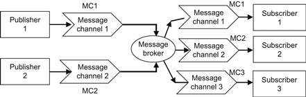
The publisher generates and publishes signals (messages) which are used by the subscriber. The broker is a signal router that monitors every module’s output channel signal and according to the signal type passes it to the input channel of each subscriber. Publishers and subscribers are actually decoupled via the message channels that are configured during the system’s initialization.
To achieve the desired (high) flexibility, implementability, and testability, the perception, planning, localization, and control tasks are decomposed into a set of simple modules. For example, localization using a GPS sensor can be split into the following two modules:
1. GPS reader module, which receives and processes messages from the GPS sensor
2. Localization module, which filters raw sensor data and updates the robot’s state
In this way, there is no need for the localization module to know how to connect and get data from the GPS sensor (i.e., changing the sensor or communication protocol does not influence localization). A typical module has the structure shown in Figure 14.26 [71].
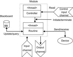
Figure 14.26 The standard module structure (which involves a controller thread and a routine thread).
An overall generic software architecture that uses the above concepts is shown in Figure 14.27 [71].

Figure 14.27 A generic architecture for a mobile robotic system based on publish–subscribe paradigm with a message broker.
The high-level modules A, B, C perform task-specific perception, planning, and control. The low-level modules perform the execution of the commands issued by the high-level modules, accept and process sensor data sending the processed data to high-level modules, and send the proper commands to the robot’s actuators. The data synchronization with each other is achieved through the publish–subscribe pattern and the shared blackboard.
In Ref. [71], the flexibility, extensibility, and testability of the above architecture was tested by constructing and applying a controller for a real automobile followed by a virtual reality model of the car. To this end, the design was based on five principal high-level modules, namely:
1. Localization module (based on a GPS sensor and an electronic compass). An extended Kalman filter was used for sensor fusion and state estimation.
2. Obstacle detection module (using a front-facing monocular camera).
3. Traffic recognition module (using a second monocular camera for the detection of traffic signs via color and shape information).
4. Planning module (which updates the status of wave-points that have been reached and decides what movement to do next).
5. Control module (with steering input set-point found using a fuzzy logic control algorithm).
The simulation experiments were based on the bicycle model of the car and a camera simulator based on the Open GL library for rendering 3D scenes. The car module is an active blackboard storing the current position, orientation, and speed of the car-like robot, while the simulator is running with 1 ms updating period. The direct communication and the publish–subscribe schemes were applied and compared. The dependency diagrams of the above two schemes are shown in Figure 14.28 [71].
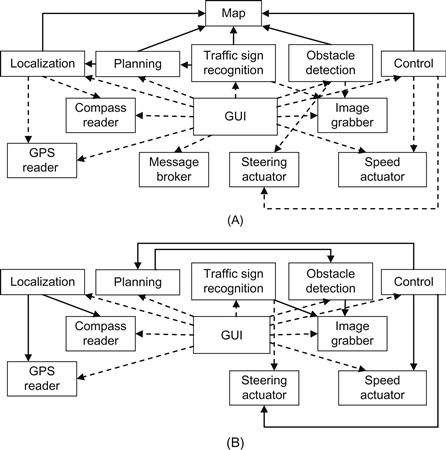
Figure 14.28 (A) Dependency diagram of the publish–subscribe scheme. (B) Dependency diagram in case of direct communication.
The overhead of the publish–subscribe scheme for message payload from 50 up to 1000 bytes was found to be 100 μs. Although it is much higher than the 10-μs overhead of the direct communication scheme, it was proved to be quite acceptable. This is so because the sensor, actuator, and control loop period is much slower.
Two other works devoted to software/middleware architectures using the blackboard concept are described in Refs. [72,73]. A comprehensive review of the middleware work on networked robots, up to 2009, is provided in Ref. [74], and an annotated literature survey with rich comments up to 2012 is given in Ref. [67].
A global picture of the features of 15 robotics middleware frameworks, as summarized in Ref. [67], can be obtained by the following list:
• OpenRTMaist, a modular software structure platform that simplifies the process of building robots by simply combining selected modules
• ASEBA, which allows distributed control and efficient resources utilization of robots with multiprocessors
• MARIE, which creates flexible distributed components that allow sharing, reusing, and integrating new or existing software programs for rapid robotic application development
• RSCA, a real-time support for robotic applications with abstractions that make them both portable and reusable on different hardware platforms
• MRDS, a robotic software platform that supports a wide variety of hardware devices and a set of useful tools facilitating programming and debugging
• OPROS, a component-based generic software platform that enables complicated functions to be developed easily by using the standardized components in the heterogeneous communication network
• CLARAty, a reusable robotic framework that enables integration, maturation, and demonstration of advanced robotic technologies, from multiple institutions on NASA’s rover platforms
• ROS, which provides OS services such as hardware abstraction, low-level device control, message-passing between processes, and package management
• OROCOS, a general-purpose modular framework for robot and machine control
• PYRO, a programming environment for easily exploring advanced topics in artificial intelligence and robotics without having to worry about the low-level details of the underlying hardware
• PLAYER, a development framework that supports different hardware devices and common services needed by different robotic applications
• ORCA, a framework that enables software reuse in robotics using component-based development
• ERSP, which provides cutting edge technologies for vision, navigation, and system development
• WEBOTS, a rapid prototyping environment for modeling, programming, and simulating mobile robots
• ROBOFRAME, a system framework that covers the special needs of autonomous lightweight robots such as dynamical locomotion and stability
Obviously, the selection of a commercial software/middleware platform for a given robotic system or application is a complex problem and needs deep and careful considerations.
References
1. Utz H, Sablantnög S, Euderde E, Kraetzschmar G. Miro-middleware for mobile robot applications. IEEE Trans Robot Autom. 2002;18(4):493–497.
2. Nesnas A, Wright A, Bajiracharya M, Simmons R, Estlin T. CLARAty and challenges of developing interoperable robotic software. Proceedings IEEE/RSJ international conference on intelligent robots and systems (IROS’2003), vol. 3. Las Vegas, NV; 2003. p. 2428–35.
3. Cote C, Brosseau Y, Letourneau D, Raivesty C, Michand F. Robotic software integration using MARIE. Int J Adv Robot Syst. 2006;3(1):55–60.
4. Gerkey B, Vaugham R, Howard A. The player/stage project: tools for multi-robot and distributed sensor systems. Proceeding of eleventh international conference on advanced robotics (ICAR’2003). Coimbra, Portugal; 2003. p. 317–323.
5. Montemerlo M, Roy N, Thrun S. Perspectives on standardization in mobile robot programming: The Carnegie Mellon Navigation (CARMEN) toolkit. Proceedings of IEEE/RSJ international conference on intelligent robotics and systems. Las Vegas, NV; 2003. p. 2436–2441.
6. Fu K-S. Learning control systems and intelligent control systems: an intersection of artificial intelligence and automatic control. IEEE Trans Autom Control. 1971;AC-16(1):70–72.
7. Saridis GN. Toward the realization of intelligent controls. Proc IEEE. 1979;67(8):1115–1133.
8. Saridis GN. Foundations of intelligent controls. Proceedings of IEEE workshop on intelligent control. Troy, NY; 1985. p. 23–8.
9. Antsaklis P, Passino KM, eds. An introduction to intelligent and autonomous systems. Berlin: Kluwer/Springer; 1993.
10. Coste-Maniére E, Simmons R. Architecture, the backbone of robotic systems. Proceedings of IEEE international conference on robotics and automation (ICRA’2000). San Francisco, CA; 2000. p. 67–72.
11. Xie W, Ma J, Yang M, Zhang Q. Research on classification of intelligent robotic architecture. J Comput. 2012;7(2):450–457.
12. Saridis GN. Analytical formulation of the principle of increasing precision and decreasing intelligence for intelligent machines. Automatica. 1989;25(3):461–467.
13. Meystel AM. Architectures of intelligent control. The science of autonomous intelligence. Proceedings of IEEE international symposium on intelligent control. Chicago, IL; 1993. p. 42–8.
14. Meystel AM. Autonomous mobile robots: vehicles with cognitive control Singapore: World Scientific Singapore; 1991.
15. Meystel AM. Multiresolutional hierarchical decision support systems. IEEE Trans Syst Man Cybern-Part C: Appl Rev. 2003;SMR-AR 33:86–101.
16. Albus JS. System description and design architecture for multiple autonomous undersea vehicles. NIST Tech. Note 1251, Washington, D.C.; September 1988.
17. Albus JS, Quintero R. Towards a reference model architecture for real-time intelligent control systems. Robotics and manufacturing. vol. 3 New York, NY: ASME; 1990.
18. Albus JM. Outline for a theory of intelligence. IEEE Trans Syst Man Cybern. 1991;SMC-21(3):473–509.
19. Ayari I, Chatti A. Reactive control using behavior modeling of a mobile robot. Int J Comput, Commun Control. 2007;2(3):217–228.
20. Brooks RA. A robust layered control system for a mobile robot. IEEE J Robot Automn. 1986;RA-2:14–23.
21. Brooks RA. Intelligence without reason. AI Memo. No. 1293, AI Laboratory, MIT; 1991.
22. Arkin RC. Motor schema-based mobile robot navigation. Int J Robot Res. 1989;8(4):92–112.
23. Arkin RC. Cooperation without communication: multi-agent schema based robot navigation. J Robot Syst. 1992;9(2):351–364.
24. Arkin RC. Behavior-based robotics Cambridge, MA: The MIT Press; 1998.
25. Oreback A, Christensen HL. Evaluation of architectures for mobile robots. Auton Robots. 2003;14:33–49.
26. Riehle D, Zullighoven H. Understanding and using patterns in software development. Theory Pract Object Syst. 1996;2(1):3–13.
27. Jawawi D, Deris S, Mamat R. Software reuse for mobile robot applications through analysis patterns. Int Arab J Inf Technol. 2007;4(3):220–228.
28. Canas JM, Matellan V. Integrating behaviors for mobile robots: an ethological approach. Cutting edge robotics Pro Literature Verlag/ARS 2005; p. 311–50.
29. Canas JM, Ruiz-Ayucar J, Aguero C, Martin F. Jde-neoc: component oriented software architecture for robotics. J Phys Agents. 2007;1(1):1–6.
30. Kerry M. Simplifying robot software design layer by layer. National Instruments RTC Magazine. <http://rtcmagazine.com/articles/view/102283>; 2013 [20 AUGUST].
31. Travis J, Kring J. LabVIEW for everyone: graphical programming made easy and fun Upper Saddle River; NJ: Prentice-Hall; 2006.
32. Konolige K., Myers K. The Saphira architecture for autonomous mobile robots. SRI International. <http://www.wv.inf.tu-dresden.de/Teaching/MobileRoboticsLab/Download/Saphira-5.3-Manual.pdf, http://www.cs.jhu.edu/~hager/Public/ICRAtutorial/Konolige-Saphira/saphira.pdf>; 2013 [20 AUGUST].
33. Lindstrom M, Oreback A, Christensen H. BERRA: a research architecture for service robots. Proceedings of IEEE international conference robotics and automation (ICRA’2000). San Francisco, CA; April 24–28, 2000. p. 3278–83.
34. Saffioti A, Ruspini E, Konolige K. Blending reactivity and goal-directness in a fuzzy controller. Proceedings of 2nd IEEE international conference on fuzzy systems. San Francisco, CA; 1993. p. 134–9.
35. Guzzoni D, Cheyer A, Julia A, Konolige K. Many robots make short work. AI Mag. 1997;18(1):55–64.
36. Schmidt DC. The ADAPTIVE communication environment: object-oriented network programming components for developing client/server applications. Proceedings of eleventh and twelveth Sun Users Group conference. San Jose, CA; June 14–17, December 7–9, 1993.
37. Fink GA. Developing HMM-based recognizers with ESMERALDA. Lecture notes in artificial intelligence. vol. 1692 Berlin: Springer; 1999; p. 229–34.
38. Veldhuizen TL. Arrays in Blitz++. Proceedings of second international scientific computing in object-oriented parallel environments: ISCOPE’ 98. Santa Fe. NM, Berlin: Springer; 1998.
39. Kramer J, Scheutz M. Development environments for autonomous mobile robots: a survey. Auton Robots. 2007;22(2):101–132.
40. Qian K, Fu X, Tao L, Xu C-W. Software architecture and design illuminated Burlington, MA: Jones and Bartlett Publishers; 2009.
41. Hirzinger G. Multisensory shared autonomy and telesensor programming: key issues in space robotics. Robot Auton Syst. 1993;11:141–162.
42. Tzafestas SG, Tzafestas ES. Human–machine interaction in intelligent robotic systems: a unifying consideration with implementation examples. J Intell Robot Syst. 2001;32(2):119–141.
43. Nilsson NJ. Shakey the robot. Technical Note No. 323, Al Center. Menlo Park, CA: SRI International; 1984.
44. Sato T, Hirai S. Language-aided robotic teleoperation system (LARTS) for advanced teleoperation. IEEE J Robot Autom. 1987;3(5):476–480.
45. Torrance MC. Natural communication with robots. MScthesis, DEEC. MA: MIT Press; 1994.
46. Heinzmann J. A safe control paradigm for human–robot interaction. J Intell Robot Syst. 1999;25:295–310.
47. Rossmann J. Virtual reality as a control and supervision tool for autonomous systems. In: Remboldt U, ed. Intell Auton Syst. Amsterdam: IOS Press; 1995;344–351.
48. Wang C, Ma H, Cannon DJ. Human–machine collaboration in robotics: integrating virtual tools with a collision avoidance concept using conglomerates of spheres. J Intell Robot Syst. 1997;18:367–397.
49. Laengle T, Remboldt U. Distributed control architecture for intelligent systems. Proceedings of international symposium on intelligent systems and advanced manufacturing. Boston, MA; November 18–22, 1996. p. 52–61.
50. Laengle T, Lueth TC, Remboldt U, Woern H. A distributed control architecture for autonomous mobile robots—implementation of the Karlsruhe multi-agent robot architecture. Adv Robot. 1998;12(4):411–431.
51. Sarkar M. Human robot interaction In-Tech, e-Books 2008.
52. Katevas NI, Sgouros NM, Tzafestas SG, et al. The autonomous mobile robot SENARIO: A sensor-aided intelligent navigation system for powered wheelchairs. IEEE Robot Autom Mag. 1997;4(4):60–70.
53. Katevas NI, Tzafestas SG, Koutsouris DG, Pnevmatikatos CG. The SENARIO autonomous navigation system. In: Tzafestas SG, editors. Mobile robotics technology for health care services. Proceedings of first MobiNet symposium. Athens; 1997. p. 87–99.
54. Ettelt E, Furtwangler R, Hanbeck UD, Schmidt G. Design issues of a semi-autonomous robotic assistant for the health care environment. J Intell Robot Syst. 1998;22(3–4):191–209.
55. Fisher C, Buss M, Schmidt G. Hierarchical supervisory control of service robot using human-robot interface. Proceedings of international conference on intelligent robots and systems (IROS’96). Osaka, Japan; 1996. p. 1408–16.
56. Fischer C, Schmidt G. Multi-modal human-robot interface for interaction with a remotely operating mobile service robot. Adv Robot. 1998;12(4):397–409.
57. Katevas NI, Tzafestas SG. The active kinematic histogram method for path planning of non-point non-holonomically constrained robots. Adv Robot. 1998;12(4):375–395.
58. Brooks A. Toward component-based robotics. Proceedings of IEEE/RSJ international conference on intelligent robots and systems (IROS 2005). Edmonton, Alberta, Canada; August 2–6, 2005. p. 163–8. <http://orca-robotics.sourceforge.net>; 2013 [20 AUGUST].
59. Scholl KU. MCA2-modular controller architecture. <http://mac2.sourceforge.net>; 2013 [20 AUGUST].
60. Brun Y, Edwards G. Engineering heterogeneous robotic systems. Computer. 2011;May:61–70.
61. Taylor RN, Medvidovic N, Dashofy EM. Software architecture: foundations, theory and practice New York, NY: John Wiley & Sons; 2009.
62. Edwards G, Garcia J, Tajalli H, et al. Architecture-driven self-adaption and self-management in robotics systems. Proceedings of international workshop on software engineering for adaptive and self-managing systems (SEAMS’09) Los Angeles, CA: IEEE Computer Society Press; March 2009; p. 142–51.
63. Medvidovic N. A language and environment for architecture based software development and evolution. Proceedings of twentyfirst international conference on software engineering (ICSE’99) IEEE Computer Science Press 1999; p. 44–53.
64. http://sunset.usc.edu/~softarch/Prism; 2013 [20 AUGUST].
65. http://omg.org; 2013 [20 AUGUST].
66. In: http://omg.org/getingstarted/corba.faq.htm.
67. Elkady A, Sobh T. Robotics middleware: a comprehensive literature survey and attributed-based bibliography. J Robot 2012 [Open Access].
68. Miro-middleware for robots. <http://orcarobotics.sourceforge.net>; 2013 [20 AUGUST].
69. Kruger D, Van Lil I, Sunderhauf N, Baumgartl, Protzel P. Using and extending the Miro middleware for autonomous mobile robots. Proceedings of international conference on towards autonomous robotic Systems (TAROS 06). Survey, UK; September 4–6, 2006. p. 90–5.
70. Steinbauer G, Fraser G, Muhlenfeld A, Wotawa A. A modular architecture for a multi-purpose mobile robot. Proceedings of seventeenth conference on industrial and engineering applications of AI and ES (IEA/AIE): innovations of artificial intelligence. Ottawa, Canada; 2004. p. 1007–15.
71. Limsoonthrakul S, Dailey ML, Sirsupundit M. A modular system architecture for autonomous robots based on blackboard and publish-subscribe mechanisms. Proceedings of IEEE international conference on robotics and biomimetics (ROBIO 2009). Bangkok, February, 22–25, 2009. p. 633–38.
72. Schneider S, Ullman M, Chen V. Controlshell: a real-time software framework. Proceedings of IEEE international conference on systems engineering. Fairborn, OH; 1991. p. 129–34.
73. Shafer S, Stentz A, Thorpe C. An architecture for sensor fusion in a mobile robot. Proceedings of IEEE international conference on robotics and automation. San Francisco, CA; April 1986. p. 2002–11.
74. Mohamed N, Al-Jaroodi J, Jawhar I. A review of middleware for networked robots. Int J Comput Sci Netw Secur. 2009;9(5):139–143.
1SENARIO Consortium: Zenon S.A. (GR), National Technical University of Athens (GR), Microsonic GmbH (DE), Reading University (UK), and Montpellier University (FR).