
Chapter 19
Drawing in a Window
WHAT YOU WILL LEARN IN THIS CHAPTER:
- How you can implement Sketcher using the model/view architecture
- How coordinates are defined for drawing on a component
- How you implement drawing on a component
- How to structure the components in a window for drawing
- What kinds of shapes you can draw on a component
- How you implement mouse listener methods to enable interactive drawing operations
In this chapter you look at how you can draw using the Java 2D facilities that are part of the Java Foundation Classes (JFC). You explore how you draw on a component in an applet and in an application. You investigate how you can combine the event-handling capability that you learned about in Chapter 18 with the drawing facilities you explore in this chapter to implement an interactive graphical user interface for creating a sketch.
USING THE MODEL/VIEW ARCHITECTURE
You need to develop an idea of how you’re going to manage the data for a sketch in the Sketcher program before you start drawing a sketch, because this affects where and how you handle events. You already have a class that defines an application window, SketcherFrame, but this class would not be a very sensible place to store the underlying data that defines a sketch. For one thing, you’ll want to save a sketch in a file, and serialization is the easiest way to do that. If you’re going to use serialization to store a sketch, you don’t want all the fields in the implementation of the SketcherFrame class muddled up with the data relating to the sketch you have created. For another thing, it makes the program easier to implement if you separate the basic data defining a sketch from the definition of the GUI. This is along the lines of the Model-View-Controller (MVC) architecture that I first mentioned in Chapter 17, a variant of which is used in the definition of Swing components. Ideally, you should manage the sketch data in a class designed specifically for that purpose. This class is the model for a sketch.
A class that represents a view of the data in the model displays the sketch and handles user interactions, so this class combines viewing methods with a sketch controller. The general GUI creation and operations that are not specific to a view are dealt with in the SketcherFrame class. This is not the only way of implementing the things you want in the Sketcher program, but it’s quite a good way.
The model object contains a mixture of text and graphics that make up a sketch. You can call the model class SketcherModel, and the class that represents a view of the model can have the name SketcherView, although you won’t be adding the view to the program until the next chapter. Figure 19-1 illustrates the relationships between the classes you have in Sketcher.

The application object has overall responsibility for managing links between the other objects involved in the program. Any object that has access to the application object is to communicate with any other object as long as the application class has methods to make each of the objects available. Thus, the application object acts as the communication channel between objects.
Note that SketcherFrame is not the view class — it just defines the application window and the GUI components associated with that. When you create a SketcherView object, you arrange to insert the SketcherView object into the content pane of the SketcherFrame object and manage it using the layout manager for the content pane. By defining the view class separately from the application class, you separate the view of a sketch from the menus and other components that you use to interact with the program. One benefit of this is that the area in which you display a sketch has its own coordinate system, independent of that of the application window.
To implement the foundations for the model/view design in Sketcher, you need to define classes for the model and the view, at least in outline. You can define in skeleton form the class to encapsulate the data that defines a sketch:
import java.io.Serializable;
import java.util.Observable;

public class SketcherModel extends Observable implements Serializable {
  // Detail of the rest of class to be filled in later...
  private final static long serialVersionUID = 1001L;
}
This is going to be Serializable because you want to save a sketch to a file. You obviously have a bit more work to do on this class to make it effective! You add to this as you go along. Because the SketcherModel class extends the Observable class, you are able to register the view class with it as an observer and automatically notify the view of any changes to the model. This facility comes into its own when you have multiple views of a sketch.
You can define the view class as a component by deriving it from the JComponent class. This builds in all the methods for operating as a Swing component and you are able to override any of these when necessary. You will be using Swing components throughout, so when I refer to a component, I mean a Swing component. The view class also needs to implement the Observer interface so that you can register it with the model to receive notification when the model changes. Here’s the outline:
import javax.swing.JComponent;
import java.util.*;

public class SketcherView extends JComponent implements Observer {
  public SketcherView(Sketcher theApp) {
    this.theApp = theApp;
  }

  // Method called by Observable object when it changes
  public void update(Observable o, Object rectangle) {
    // Code to respond to changes in the model...
  }

  private Sketcher theApp;           // The application object
}
Directory "Sketcher 1 drawing a 3D rectangle"
The view needs access to the model to display it, but rather than store a reference to the model in the view, the constructor has a parameter to enable the application object to be passed to it. The view object is able to use the application object to access the model object, and the application window if necessary.
The view is registered as an observer for the model. If a completely different object represents the model because, for example, a new file is loaded, the view object is automatically notified by the model that it has changed and is able to respond by redrawing the view.
To integrate a model and its view into the Sketcher application, you just need to add some code to the Sketcher class that defines the application object:
import javax.swing.*;
import java.awt.*;
import java.awt.event.*;

public class Sketcher {
  public static void main(String[] args) {
   theApp = new Sketcher();                              // Create the application object
   SwingUtilities.invokeLater(new Runnable() {
            public void run() {
                          theApp.createGUI();            // Call GUI creator
            }
        });

  // Method to create the application GUI
  private void createGUI() {
    window = new SketcherFrame("Sketcher", this);    // Create the app window
    Toolkit theKit = window.getToolkit();                // Get the window toolkit
    Dimension wndSize = theKit.getScreenSize();          // Get screen size

    // Set the position to screen center & size to half screen size
    window.setSize(wndSize.width/2, wndSize.height/2);   // Set window size
    window.setLocationRelativeTo(null);                  // Center window
    window.addWindowListener(new WindowHandler());       // Add window listener

    sketch = new SketcherModel();                    // Create the model
    view = new SketcherView(this);                   // Create the view
    sketch.addObserver(view);                        // Register view with the model
    window.getContentPane().add(view, BorderLayout.CENTER);
    window.setVisible(true);
  }

  // Return a reference to the application window
  public SketcherFrame getWindow() {
     return window;
  }

  // Return a reference to the model
  public SketcherModel getModel() {
     return sketch;
  }

  // Return a reference to the view
  public SketcherView getView() {
     return view;
  }

  // Handler class for window events
  class WindowHandler extends WindowAdapter {
    // Handler for window closing event
    @Override
    public void windowClosing(WindowEvent e) {
      // Code to be added here later...
    }
  }

  private SketcherModel sketch;             // The data model for the sketch
  private SketcherView view;                // The view of the sketch
  private static SketcherFrame window;         // The application window
  private static Sketcher theApp;              // The application object
}
Directory "Sketcher 1 drawing a 3D rectangle"
The SketcherFrame constructor that you defined in the previous chapter needs to be modified as follows:
  public SketcherFrame(String title, Sketcher theApp) {
    setTitle(title);                           // Set the window title
     this.theApp = theApp;                   // Save app. object reference
    setJMenuBar(menuBar);                      // Add the menu bar to the window
    setDefaultCloseOperation(EXIT_ON_CLOSE);   // Default is exit the application

    // Rest of the constructor as before...
  }
Directory "Sketcher 1 drawing a 3D rectangle"
You can add a field to the SketcherFrame class that stores the reference to the application object:
private Sketcher theApp; // The application object
There are new methods in the Sketcher class that return a reference to the application window, the model, and the view, so all of these are now accessible from anywhere in the Sketcher application code where you have a reference to the application object available.
After creating the model and view objects in the createGUI() method in the Sketcher class, you register the view as an observer for the model to enable the model to notify the view when any changes occur. You then add the view to the content pane of the window object, which is the main application window. Because you add the view in the center using the BorderLayout manager for the content pane, it occupies all the remaining space in the pane.
You now know roughly the direction in which you are heading, so let’s move on down the road.
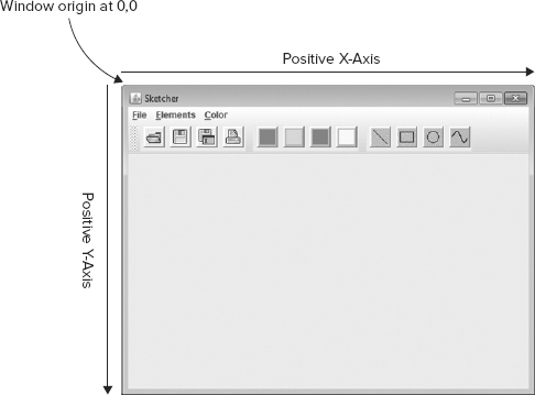
In Chapter 17, you saw how your computer screen has a coordinate system that is used to define the position and size of a window. You also saw how you can add components to a container with their position established by a layout manager. The coordinate system that is used by a container to position components within it is analogous to the screen coordinate system. The origin is at the top-left corner of the container, with the positive x-axis running horizontally from left to right, and the positive y-axis running from top to bottom. The positions of buttons in a JWindow or a JFrame object are specified as a pair of (x,y) coordinates, relative to the origin at the top-left corner of the container object on the screen. In Figure 19-2 you can see the coordinate system for the Sketcher application window.
Of course, the layered pane for the window object has its own coordinate system, with the origin in the top-left corner of the pane, and this is used to position the menu and the content pane. The content pane has its own coordinate system, too, which is used to position the components that it contains.
It’s not just containers and windows that have their own coordinate system: Each JButton object also has its own system, as do JToolBar objects. In fact, every component has its own coordinate system, and an example is shown in Figure 19-3.

The toolbar and the buttons each have their own independent coordinate systems with the origin in the top-left corner. It’s clear that a container needs a coordinate system for specifying the positions of the components it contains. You also need a coordinate system to draw on a component — to draw a line, for example, you need to be able to specify where it begins and ends in relation to the component. Although the coordinate system you use for drawing on a component is similar to that used for positioning components in a container, it’s not exactly the same. It’s more complicated when you are drawing — but for very good reasons. Let’s see how the coordinate system for drawing works.
Before I get into the specifics of how you draw on a Swing component, I will explain the principle ideas behind it. When you draw on a component using the Java 2D capabilities, two coordinate systems are involved. When you draw something — a line or a curve, for example — you specify the line or the curve in a device-independent logical coordinate system called the user coordinate system for the component, or user space. By default, this coordinate system has the same orientation as the system that I discussed for positioning components in containers. The origin is at the top-left corner of the component; the positive x-axis runs from left to right, and the positive y-axis from top to bottom. Coordinates are usually specified as floating-point values, although you can also use integers.
A particular graphical output device has its own device coordinate system, or device space, as illustrated in Figure 19-4. This coordinate system has the same orientation as the default user coordinate system, but the coordinate units depend on the characteristics of the device. Your display, for example, has a different device coordinate system for each configuration of the screen resolution, so the coordinate system when your display is set to a resolution 1024 × 768 pixels is different from the coordinate system for 1920× 1080 pixels.

NOTE Incidentally, the drawing process is often referred to as rendering. Graphical output devices are generally raster devices that display an image as a rectangular array of pixels and drawing elements such as lines, rectangles, text, and so on need to be rendered into a rasterized representation before they can be output to the device.
Having a device-independent coordinate system for drawing means that you can use essentially the same code for writing graphical information to a variety of different devices — to your display screen, for example, or to your printer — even though these devices themselves have quite different coordinate systems with different resolutions. The fact that your screen might have 90 pixels per inch and your printer may have 600 dots per inch is automatically taken care of. Java 2D deals with converting your user coordinates to the device coordinate system that is specific to the output device you are using.
Graphics Contexts
The user coordinate system for drawing on a component using Java 2D is encapsulated in an object of type java.awt.Graphics2D, which is usually referred to as a graphics context. It provides all the tools you need to draw whatever you want on the surface of the component. A graphics context enables you to draw lines, curves, shapes, filled shapes, as well as images, and gives you a great deal of control over the drawing process.
The Graphics2D class is derived from the java.awt.Graphics class and references to graphics contexts are usually passed around as type Graphics, so you need to be aware of it. This is because the Component class defines a getGraphics() method that returns a reference to a graphics context as type Graphics and the Swing component classes, which are subclasses of Component, typically override this method. Note that both the Graphics and Graphics2D classes are abstract classes, so you can’t create objects of either type directly. An object representing a graphics context is entirely dependent on the component to which it relates, so a graphics context is always obtained for use with a particular component.
The Graphics2D object for a component takes care of mapping user coordinates to device coordinates, so it contains information about the device that is the destination for output as well as the user coordinates for the component. The information required for converting user coordinates to device coordinates is encapsulated in objects of three different types that are defined in the java.awt package:
- A GraphicsEnvironment object encapsulates all the graphics devices (as GraphicsDevice objects) and fonts (as Font objects) that are available to a Java application on your computer.
- A GraphicsDevice object encapsulates information about a particular device, such as a screen or a printer, and stores it in one or more GraphicsConfiguration objects.
- A GraphicsConfiguration object defines the characteristics of a particular device, such as a screen or a printer. Your display screen typically has several GraphicsConfiguration objects associated with it, each corresponding to a particular combination of screen resolution and number of displayable colors.
The graphics context also maintains other information necessary for drawing operations, such as the drawing color, the line style, and the specification of the fill color and pattern for filled shapes. You see how to work with these attributes in examples later in this chapter.
Because a graphics context defines the drawing context for a specific component, you must have a reference to the graphics context object for a component before you can draw on the component. For the most part, you draw on a component by implementing the paint() method that is inherited from JComponent. This method is called whenever the component needs to be reconstructed. A reference to an object representing the graphics context for the component is passed as an argument to the paint() method, and you use this object to do the drawing. The graphics context includes all the methods that you use to draw on a component, and I’ll introduce you to many of these in this chapter.
The paint() method is not the only way of drawing on a component. You can obtain a graphics context for a component at any time just by calling its getGraphics() method. You can then use methods for the Graphics object to specify the drawing operations.
There are occasions when you want to get a component redrawn while avoiding a direct call of the paint() method. In such cases you should call repaint() for the component, versions of which are inherited in a Swing component class from the Component and JComponent classes. This situation arises when you make a succession of changes to what is drawn on a component, but want to defer redrawing the component until all the changes have been made. Five versions of the repaint() method are available; here are four of them:
- repaint() causes the entire component to be repainted by calling its paint() method after all the currently outstanding events have been processed.
- repaint(long msec) requests that a call to paint() should occur within msec milliseconds.
- repaint(int msec, int x,int y,int width, int height) adds the region specified by the arguments to the dirty region list if the component is visible. The dirty region list is simply a list of areas of the component that need to be repainted. The component is repainted by calling its paint() method when all currently outstanding events have been processed, or within msec milliseconds. The region is the rectangle at position (x, y), with the width and height as specified by the last two arguments.
- repaint(Rectangle rect) adds the rectangle specified by rect to the dirty region list if the component is visible. The dirty region is the area to be repainted when the component is next redrawn.
You will find that the first and the last methods are the ones you use most of the time.
That’s enough theory for now. It’s time to get a bit of practice. Let’s get an idea of how you can draw on a component by drawing on the SketcherView object that you added to Sketcher. All you need to do is implement the paint() method in the SketcherView class that you added earlier in this chapter.
TRY IT OUT: Drawing in a View
You are going to modify Sketcher temporarily to make it display a 3D rectangle. Add the following implementation of the paint() method to the SketcherView class:
import javax.swing.JComponent;
import java.util.*;
import java.awt.*;

class SketcherView extends JComponent implements Observer {
  // Method to draw on the view
  @Override
  public void paint(Graphics g) {
    // Temporary code to be replaced later...
    Graphics2D g2D = (Graphics2D)g;                  // Get a Java 2D device context

    g2D.setPaint(Color.RED);                         // Draw in red
    g2D.draw3DRect(50, 50, 150, 100, true);          // Draw a raised 3D rectangle
    g2D.drawString("A nice 3D rectangle", 60, 100);  // Draw some text
  }
  // Rest of the class as before...
}
Directory "Sketcher 1 drawing a 3D rectangle"
If you recompile the SketcherFrame.java file and run Sketcher once again, you can see what the paint() method produces. You should see the window shown in Figure 19-5.

Okay, it’s not 3D in the usual sense and you probably can’t see the effect in the book. In this case, the edges of the rectangle are highlighted so that they appear to be beveled and lift from the top left-hand corner (or the coordinate origin).
How It Works
The graphics context is passed as the argument to the paint() method as type Graphics, the base class for Graphics2D, so to use the methods defined in the Graphics2D class you must first cast it to that type.
After you have cast the graphics context object, you set the color in which you draw by calling the setPaint() method for the Graphics2D object with the drawing color as the argument. All subsequent drawing operations are now in the color Color.RED. You can change this with another call to setPaint() whenever you want to draw in a different color.
Next, you call the draw3DRect() method for the Graphics2D object, and this draws the 3D rectangle. The first two arguments are integers specifying the x and y coordinates of the top-left corner of the rectangle to be drawn, relative to the user space origin of the component, which in this case is the top-left corner of the view object in the content pane. The third and fourth arguments are integers specifying the width and height of the rectangle respectively, also in units determined by the user coordinate system. The fifth argument is a boolean value that makes the rectangle appear to be raised when the value is true.
The drawString() method draws the string specified as the first argument at the position determined by the second and third arguments — these are the x and y coordinates in user coordinates of the bottom-left corner of the first letter of the string. The string is drawn by obtaining the glyphs for the current Font object in the device context corresponding to the characters in the string. As I said when I discussed Font objects, the glyphs for a font define the physical appearance of the characters.
However, there’s more to drawing than is apparent from this example. The graphics context has information about the line style to be drawn, as well as the color, the font to be used for text, and more besides. Let’s dig a little deeper into what is going on.
The Drawing Process
A Graphics2D object maintains a whole heap of information that determines how things are drawn. Most of this information is contained in six attributes within a Graphics2D object:
- Paint: Determines the drawing color for lines. It also defines the color and pattern to be used for filling shapes. The paint attribute is set by calling the setPaint(Paint paint) method for the graphics context. java.awt.Paint is an interface that is implemented by the Color class that defines a color. It is also implemented by the java.awt.GradientPaint and java.awt.TexturePaint classes, which represent a color pattern and a texture, respectively. You can therefore pass references of any of these types to the setPaint() method. The default paint attribute is the color of the component.
- Stroke: Defines a pen that determines the line style, such as solid, dashed, or dotted lines, and the line thickness. It also determines the shape of the ends of lines. The stroke attribute is set by calling the setStroke(Stroke s) method for a graphics context. The default stroke attribute defines a square pen that draws a solid line with a thickness of one user coordinate unit. The ends of the line are square, and joins are mitered (i.e., the line ends are beveled where lines join so they fit together). The java.awt.Stroke interface is implemented by the java.awt.BasicStroke class, which defines a basic set of attributes for rendering lines.
- Font: Determines the font to be used when drawing text. The font attribute is set by calling the setFont(Font font) method for the graphics context. The default font is the font set for the component.
- Transform: Defines the transformations to be applied during the rendering process. What you draw can be translated, rotated, and scaled as determined by the transforms currently in effect. There are several methods for applying transforms to what is drawn, as you see later. The default transform is the identity transform, which leaves things unchanged.
- Clip: Defines the boundary of an area on a component. Rendering operations are restricted so that drawing takes place only within the area enclosed by the clip boundary. The clip attribute is set by calling one of the two setClip() methods for a graphics context. With one version of setClip() you define the boundary of the area to be rendered as a rectangle that you specify by the coordinates of its top-left corner and the width and height of the rectangle. The other setClip() method expects the argument to be a reference of type java.awt.Shape. The Shape interface is implemented by a variety of classes in the java.awt.geom package that define geometric shapes of various kinds, such as lines, circles, polygons, and curves. The default clip attribute is the whole component area.
- Composite: Determines how overlapping shapes are drawn on a component. You can alter the transparency of the fill color of a shape so an underlying shape shows through. You set the composite attribute by calling the setComposite(Composite comp) method for the graphics context. The default composite attribute causes a new shape to be drawn over whatever is already there, taking account of the transparency of any of the colors used.
All the objects that represent attributes are stored as references within a Graphics2D object. Therefore, you must always call a setXXX() method to alter an attribute in a graphics context, not try to modify an external object directly. If you externally alter an object that has been used to set an attribute, the results are unpredictable.
NOTE You can also affect how the rendering process deals with “jaggies" when drawing lines. The process to eliminate jaggies on sloping lines is called antialiasing, and you can change the antialiasing that is applied by calling one of the two setRenderingHints() methods for a graphics context. I don’t go into this aspect of drawing further, though.
There’s a huge amount of detail on attributes under the covers. Rather than going into all that here, you explore how to apply new attributes to a graphics context piecemeal where it is relevant to the various examples you create.
Rendering Operations
You have the following basic methods available with a Graphics2D object for rendering various kinds of graphic entities:
- draw(Shape shape) renders a shape using the current attributes for the graphics context. I discuss what a shape is next.
- fill(Shape shape) fills a shape using the current attributes for the graphics context. You see how to do this later in this chapter.
- drawString(String text) renders a text string using the current attributes for the graphics context. You apply this further in the next chapter.
This is very much a subset of the methods available in the Graphics2D class. I concentrate on those that draw shapes and strings that I have identified here. Let’s see what shapes are available; they’ll help make Sketcher a lot more useful.
Classes that define geometric shapes are contained in the java.awt.geom package, but the Shape interface that these classes implement is defined in java.awt. Objects that represent shapes are often passed around as references of type Shape, so you often need to import class names from both packages into your source file. Any class that implements the Shape interface defines a shape, and visually a shape is some composite of straight lines and curves. Straight lines, rectangles, ellipses, and curves are all shapes.
A graphics context knows how to draw objects of a type that implements the Shape interface. To draw a shape on a component, you just need to pass the object defining the shape to the draw() method for the Graphics2D object for the component. To explore this in detail, I split the shapes into three groups: straight lines and rectangles, arcs and ellipses, and freeform curves. First, though, you must take a look at how points are defined.
Classes Defining Points
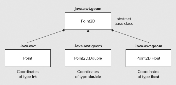
Two classes in the java.awt.geom package define points: Point2D.Float and Point2D.Double. From the class names you can see that these are both inner classes to the Point2D class, which also happens to be an abstract base class for both classes, too. The Point2D.Float class defines a point from a pair of (x,y) coordinates of type float, whereas the Point2D.Double class defines a point as a coordinate pair of type double. The Point class in the java.awt package also defines a point, but in terms of a coordinate pair of type int. The Point class also has Point2D as a base, and the hierarchy of classes that represents points is shown in Figure 19-6.
The Point class actually predates the Point2D class, but the Point class was redefined to make it a subclass of Point2D when Point2D was introduced, hence the somewhat unusual class hierarchy with only two of the subclasses as static nested classes. The merit of this arrangement is that all of the subclasses inherit the methods defined in the Point2D class, so operations on each of the three kinds of point are the same. Objects of all three concrete types that represent points can be passed around as references of type Point2D.
The three subclasses of Point2D define a default constructor that defines the point (0,0) and a constructor that accepts a pair of coordinates of the type appropriate to the class type.
Each of the three concrete point classes inherits the following operations:
1. Accessing coordinate values: The getX() and getY() methods return the x and y coordinates of a point as type double, regardless of how the coordinates are stored. These are abstract methods in the Point2D class, so they are defined in each of the subclasses. Although you get coordinates as values of type double from all three concrete classes via these methods, you can always access the coordinates with their original type directly because the coordinates are stored in public fields with the same names, x and y, in each case.
2. Calculating the distance between two points: You have no less than three overloaded versions of the distance() method for calculating the distance between two points and returning it as type double:
- distance(double x1,double y1, double x2,double y2): This is a static version of the method that calculates the distance between the points (x1, y1) and (x2, y2).
- distance(double xNext,double yNext): This calculates the distance from the current point (the object for which the method is called) and the point (xNext, yNext).
- distance(Point2D nextPoint): This calculates the distance from the current point to the point nextPoint. The argument can be any of the subclass types, Point, Point2D.Float, or Point2D.Double.
Here’s how you might calculate the distance between two points:
Point2D.Double p1 = new Point2D.Double(2.5, 3.5);
Point p2 = new Point(20, 30);
double lineLength = p1.distance(p2);
You can also calculate this distance without creating the points by using the static method:
double lineLength = Point2D.distance(2.5, 3.5, 20, 30);
Corresponding to each of the three distance() methods is a convenience method, distanceSq(), with the same parameter list that returns the square of the distance between two points as a value of type double.
3. Comparing points: The equals() method compares the current point with the point object referenced by the argument and returns true if they are equal and false otherwise.
4. Setting a new location for a point: The setLocation() method comes in two versions. One accepts an argument that is a reference of type Point2D and sets the coordinate values of the current point to those of the point passed as an argument. The other accepts arguments of type double that are the x and y coordinates of the new location. The Point class also defines a version of setLocation() that accepts two arguments of type int to define the new coordinates.
Lines and Rectangles
The java.awt.geom package contains the following classes for shapes that are straight lines and rectangles:
- Line2D: This is an abstract base class defining a line between two points. Two concrete subclasses — Line2D.Float and Line2D.Double — define lines in terms of user coordinates of type float and double, respectively. You can see from their names that the subclasses are nested classes to the abstract base class Line2D.
- Rectangle2D: This is the abstract base class for the Rectangle2D.Double and Rectangle2D.Float classes that define rectangles. A rectangle is defined by the coordinates of the position of its top-left corner plus its width and height. The Rectangle2D class is also the abstract base class for the Rectangle class in the java.awt package, which stores the position coordinates and the height and width as values of type int.
- RoundRectangle2D: This is the abstract base class for the RoundRectangle2D.Double and RoundRectangle2D.Float classes, which define rectangles with rounded corners. The rounded corners are specified by a width and height.
Like the java.awt.Point class, the java.awt.Rectangle class predates the Rectangle2D class, but the definition of the Rectangle class was changed to make Rectangle2D a base for compatibility reasons. Note that there is no equivalent to the Rectangle class for lines defined by integer coordinates. If you are browsing the documentation, you might notice there is a Line interface, but this declares operations for an audio channel and has nothing to do with geometry.
Figure 19-7 illustrates how, lines, rectangles, and round rectangles are defined.

You can define a line by supplying two Point2D objects to a constructor, or two pairs of (x,y) coordinates. For example, here’s how you define a line by two coordinate pairs:
Line2D.float line = new Line2D.Float(5.0f, 100.0f, 50.0f, 150.0f);
This draws a line from the point (5.0, 100.0) to the point (50.0, 150.0). You could also create the same line using Point2D.Float objects, like this:
Point2D.Float p1 = new Point2D.Float(5.0f, 100.0f);
Point2D.Float p2 = new Point2D.Float(50.0f, 150.0f);
Line2D.float line = new Line2D.Float(p1, p2);
You draw a line on a component using the draw() method for a Graphics2D object. For example:
g2D.draw(line); // Draw the line
To create a rectangle, you specify the coordinates of its top-left corner, and the width and height of the rectangle:
float width = 120.0f;
float height = 90.0f;
Rectangle2D.Float rectangle = new Rectangle2D.Float(50.0f, 150.0f, width, height);
The default constructor creates a rectangle at the origin with a zero width and height. You can set the position, width, and height of a rectangle by calling its setRect() method. There are three versions of this method. One of them accepts arguments for the coordinates of the top-left corner and the width and height as values of type float, exactly as in the constructor. Another accepts arguments with the same meaning but of type double. The third setRect() method accepts an argument of type Rectangle2D, so you can pass any type of rectangle object to it.
A Rectangle2D object has getX() and getY() methods for retrieving the coordinates of the top-left corner, and getWidth() and getHeight() methods that return the width and height of the rectangle, respectively.
A round rectangle is a rectangle with rounded corners. The corners are defined by a width and a height and are essentially a quarter segment of an ellipse (I get to the details of ellipses later). Of course, if the corner width and height are equal, then the corner is a quarter of a circle.
You can define a round rectangle using coordinates of type double with the following statements:
Point2D.Double position = new Point2D.Double(10, 10);
double width = 200.0;
double height = 100;
double cornerWidth = 15.0;
double cornerHeight = 10.0;
RoundRectangle2D.Double roundRect = new RoundRectangle2D.Double(
                       position.x, position.y,                      // Position of top-left
                       width, height,                               // Rectangle width & height
                       cornerWidth, cornerHeight);                  // Corner width & height
The only difference between this and defining an ordinary rectangle is the addition of the width and height to be applied for the corner rounding.
Combining Rectangles
You can combine two rectangles to produce a new rectangle that is either the union of the two original rectangles or the intersection. The union of two rectangles is the smallest rectangle enclosing both. The intersection is the rectangle that is common to both. Let’s take a couple of specifics to see how this works. You can create two rectangles with the following statements:
float width = 120.0f;
float height = 90.0f;
Rectangle2D.Float rect1 = new Rectangle2D.Float(50.0f, 150.0f, width, height);
Rectangle2D.Float rect2 = new Rectangle2D.Float(80.0f, 180.0f, width, height);
You can obtain the intersection of the two rectangles with the following statement:
Rectangle2D.Float rect3 = rect1.createIntersection(rect2);
The effect is illustrated in Figure 19-8 by the shaded rectangle. Of course, the result is the same if you call the method for rect2 with rect1 as the argument. If the rectangles don’t overlap, the rectangle that is returned is the rectangle from the bottom right of one rectangle to the top right of the other that does not overlap either of the original rectangles.

The following statement produces the union of the two rectangles:
Rectangle2D.Float rect3 = rect1.createUnion(rect2);
The result is shown in Figure 19-8 by the rectangle with the heavy boundary that encloses the other two.
Testing Rectangles
Perhaps the simplest test you can apply to a Rectangle2D object is for an empty rectangle. The isEmpty() method that is implemented in all the rectangle classes returns true if the Rectangle2D object is empty — which is when either the width or the height (or both) are zero.
You can also test whether a point lies inside any type of rectangle object by calling its contains() method. There are contains() methods for all the rectangle classes that accept either a Point2D argument, or a pair of (x,y) coordinates of a type matching that of the rectangle class: They return true if the point lies within the rectangle and false otherwise. Every shape class defines a getBounds2D() method that returns a Rectangle2D object that encloses the shape.
The getBounds2D() method is frequently used in association with the contains() method to provide an efficient test of whether the cursor lies within a particular shape. Testing whether the cursor is within the enclosing rectangle is a lot faster in general than testing whether it is within the precise boundary of the shape and is good enough for many purposes — for example, when you are selecting a particular shape on the screen to manipulate it in some way.
You also have versions of the contains() method to test whether a given rectangle lies within the area occupied by a rectangle object — this obviously enables you to test whether a shape lies within another shape. You can pass the given rectangle to the contains() method as the coordinates of its top-left corner, and its height and width as type double, or as a Rectangle2D reference. The method returns true if the rectangle object completely contains the given rectangle.
Let’s try drawing a few simple lines and rectangles by inserting some code in the paint() method for the view in Sketcher.
TRY IT OUT: Drawing Lines and Rectangles
Begin by adding an import statement to SketcherView.java for the class names from the java.awt.geom package:
import java.awt.geom.*;
Now you can replace the previous code in the paint() method in the SketcherView class with the following:
  @Override
  public void paint(Graphics g) {
    // Temporary code - to be deleted later...
    Graphics2D g2D = (Graphics2D)g;             // Get a Java 2D device context

    g2D.setPaint(Color.RED);                    // Draw in red

    // Position width and height of first rectangle
    Point2D.Float p1 = new Point2D.Float(50.0f, 10.0f);
    float width1 = 60;
    float height1 = 80;

    // Create and draw the first rectangle
    Rectangle2D.Float rect = new Rectangle2D.Float(p1.x, p1.y, width1, height1);
    g2D.draw(rect);

    // Position width and height of second rectangle
    Point2D.Float p2 = new Point2D.Float(150.0f, 100.0f);
    float width2 = width1 + 30;
    float height2 = height1 + 40;

    // Create and draw the second rectangle
    g2D.draw(new Rectangle2D.Float((float)(p2.getX()), (float)(p2.getY()), width2, height2));
    g2D.setPaint(Color.BLUE);                   // Draw in blue

    // Draw lines to join corresponding corners of the rectangles
    Line2D.Float line = new Line2D.Float(p1,p2);
    g2D.draw(line);

    p1.setLocation(p1.x + width1, p1.y);
    p2.setLocation(p2.x + width2, p2.y);
    g2D.draw(new Line2D.Float(p1,p2));

    p1.setLocation(p1.x, p1.y + height1);
    p2.setLocation(p2.x, p2.y + height2);
    g2D.draw(new Line2D.Float(p1,p2));

    p1.setLocation(p1.x - width1, p1.y);
    p2.setLocation(p2.x - width2, p2.y);
    g2D.draw(new Line2D.Float(p1, p2));

    p1.setLocation(p1.x, p1.y - height1);
    p2.setLocation(p2.x, p2.y - height2);
    g2D.draw(new Line2D.Float(p1, p2));

    g2D.drawString("Lines and rectangles", 60, 250); // Draw some text
  }
Directory "Sketcher 2 drawing lines and rectangles"
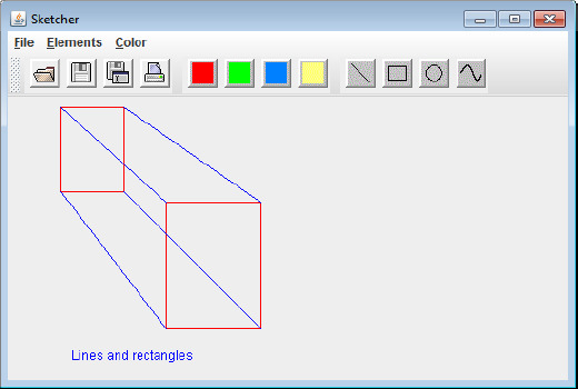
If you type this code in correctly and recompile the SketcherView class, the Sketcher window looks like the one shown in Figure 19-9.
How It Works
After casting the graphics context object that is passed to the paint() method to type Graphics2D, you set the drawing color to red. All subsequent drawing that you do is in red until you change the color with another call to setPaint(). You define a Point2D.Float object to represent the position of the first rectangle, and you define variables to hold the width and height of the rectangle. You use these to create the rectangle by passing them as arguments to the constructor that you saw earlier in this chapter and display the rectangle by passing the rect object to the draw() method for the graphics context, g2D. The second rectangle is defined by essentially the same process, except that this time you create the Rectangle2D.Float object in the argument expression for the draw() method.
Note that you have to cast the values returned by the getX() and getY() members of the Point2D object, as they are returned as type double. It is generally more convenient to reference the x and y fields directly as you do in the rest of the code.
You change the drawing color to blue so that you can see quite clearly the lines you are drawing. You use the setLocation() method for the point objects to move the point on each rectangle to successive corners and draw a line at each position. The caption also appears in blue because that is the color in effect when you call the drawString() method to output the text string.
Arcs and Ellipses
There are shape classes defining both arcs and ellipses. The abstract class representing a generic ellipse is:
- Ellipse2D: This is the abstract base class for the Ellipse2D.Double and Ellipse2D.Float classes that define ellipses. An ellipse is defined by the top-left corner, width, and height of the rectangle that encloses it.
- Arc2D: This is the abstract base class for the Arc2D.Double and Arc2D.Float classes that define arcs as a portion of an ellipse. The full ellipse is defined by the position of the top-left corner and the width and height of the rectangle that encloses it. The arc length is defined by a start angle measured in degrees counterclockwise relative to the horizontal axis of the full ellipse, plus an angular extent measured anticlockwise from the start angle in degrees. You can specify an arc as OPEN, which means the ends are not connected; as CHORD, which means the ends are connected by a straight line; or as PIE, which means the ends are connected by straight lines to the center of the whole ellipse. These constants are defined as static members of the Arc2D class.
Arcs and ellipses are closely related because an arc is just a segment of an ellipse. Constructors for the Ellipse2D.Float and Arc2d.Float classes are shown in Figure 19-10. To define an ellipse you supply the data necessary to define the enclosing rectangle — the coordinates of the top-left corner, the width, and the height. To define an arc you supply the data to define the ellipse, plus additional data that defines the segment of the ellipse that you want. The seventh argument to the arc constructor determines the type, whether OPEN, CHORD, or PIE.

You could define an ellipse with the following statements:
Point2D.Double position = new Point2D.Double(10,10);
double width = 200.0;
double height = 100;
Ellipse2D.Double ellipse = new Ellipse2D.Double(
                         position.x, position.y, // Top-left corner
                         width, height);         // width & height of rectangle
You could define an arc that is a segment of the previous ellipse with this statement:
Arc2D.Double arc = new Arc2D.Double(
                        position.x, position.y,  // Top-left corner
                        width, height,           // width & height of rectangle
                        0.0, 90.0,               // Start and extent angles
                        Arc2D.OPEN);             // Arc is open
This defines the upper-right quarter segment of the whole ellipse as an open arc. The angles are measured counterclockwise from the horizontal in degrees. As shown in Figure 19-10, the first angular argument is where the arc starts, and the second is the angular extent of the arc.
Of course, a circle is just an ellipse for which the width and height are the same, so the following statement defines a circle with a diameter of 150:
double diameter = 150.0;
Ellipse2D.Double circle = new Ellipse2D.Double(
                      position.x, position.y,    // Top-left corner
                      diameter, diameter);       // width & height of rectangle
This presumes the point position is defined somewhere. You often want to define a circle by its center and radius — adjusting the arguments to the constructor a little does this easily:
Point2D.Double center = new Point2D.Double(200, 200);
double radius = 150;
Ellipse2D.Double newCircle = new Ellipse2D.Double(
          center.x-radius, center.y-radius,      // Top-left corner
          2*radius, 2*radius);                   // width & height of rectangle
The fields that stores the coordinates of the top-left corner of the enclosing rectangle and the width and height are public members of Ellipse2D and Arc2D objects. They are x, y, width, and height, respectively. An Arc2D object also has public members, start and extent, that store the angles.
TRY IT OUT: Drawing Arcs and Ellipses
Let’s modify the paint() method in SketcherView.java once again to draw some arcs and ellipses. Replace the code in the body of the paint() method with the following:
  @Override
  public void paint(Graphics g) {
    // Temporary code - to be deleted later...
    Graphics2D g2D = (Graphics2D)g;                      // Get a 2D device context
    Point2D.Double position = new Point2D.Double(50,10); // Initial position
    double width = 150;                                  // Width of ellipse
    double height = 100;                                 // Height of ellipse
    double start = 30;                                   // Start angle for arc
    double extent = 120;                                 // Extent of arc
    double diameter = 40;                                // Diameter of circle

    // Define open arc as an upper segment of an ellipse
    Arc2D.Double top = new Arc2D.Double(position.x, position.y,
                                        width, height,
                                        start, extent,
                                        Arc2D.OPEN);

    // Define open arc as lower segment of ellipse shifted up relative to 1st
    Arc2D.Double bottom = new Arc2D.Double(
                                 position.x, position.y - height + diameter,
                                 width, height,
                                 start + 180, extent,
                                 Arc2D.OPEN);

    // Create a circle centered between the two arcs
    Ellipse2D.Double circle1 = new Ellipse2D.Double(
                                 position.x + width/2 - diameter/2,position.y,
                                 diameter, diameter);

    // Create a second circle concentric with the first and half the diameter
    Ellipse2D.Double circle2 = new Ellipse2D.Double(
                   position.x + width/2 - diameter/4, position.y + diameter/4,
                   diameter/2, diameter/2);

    // Draw all the shapes
    g2D.setPaint(Color.BLACK);                       // Draw in black
    g2D.draw(top);
    g2D.draw(bottom);

    g2D.setPaint(Color.BLUE);                        // Draw in blue
    g2D.draw(circle1);
    g2D.draw(circle2);
    g2D.drawString("Arcs and ellipses", 80, 100);    // Draw some text
  }
Directory "Sketcher 3 drawing arcs and ellipses"
Running Sketcher with this version of the paint() method in SketcherView produces the window shown in Figure 19-11.

How It Works
This time you create all the shapes first and then draw them. The two arcs are segments of ellipses of the same height and width. The lower arc segment is shifted up with respect to the first arc segment so that they intersect, and the distance between the top of the rectangle for the first arc and the bottom of the rectangle for the second arc is diameter, which is the diameter of the first circle you create.
Both circles are created centered between the two arcs and are concentric. Finally, you draw all the shapes — the arcs in black and the circles in blue.
Next time you change the code in Sketcher, you build the application as it should be, so you can now remove the temporary code from the paint() method and, if you haven’t done so already, also remove the code that sets the background color in the ColorAction inner class to the SketcherFrame class.
Curves
There are two classes that define arbitrary curves, one defining a quadratic or second-order curve, and the other defining a cubic curve. These arbitrary curves are parametric curves defined by a sequence of curve segments. A quadratic curve segment is defined by an equation that includes squares of the independent variable, x. A cubic curve is defined by an equation that includes cubes of the independent variable, x. The cubic curve just happens to be a Bézier curve (so called because it was developed by a Frenchman, Monsieur Pierre Bézier, and first applied in the context of defining contours for programming numerically controlled machine tools for manufacturing car body forms).
The classes defining these curves are:
- QuadCurve2D: This is the abstract base class for the QuadCurve2D.Double and QuadCurve2D.Float classes that define a quadratic curve segment. The curve is defined by its end points plus a control point that defines the tangent at each end. The tangents are the lines from the end points to the control point.
- CubicCurve2D: This is the abstract base class for the CubicCurve2D.Double and CubicCurve2D.Float classes that define a cubic curve segment. The curve is defined by its end points plus two control points that define the tangent at each end. The tangents are the lines from the end points to the corresponding control point.
Figure 19-12 illustrates how the control points relate to the curves in each case. In general, there are many other methods for modeling arbitrary curves, but the two defined in Java have the merit that they are both easy to understand, and the effect on the curve segment when you move a control point is quite intuitive.
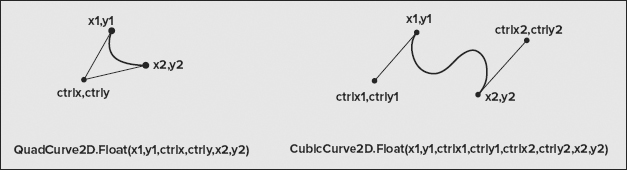
An object of a curve type defines a curve segment between two points. The control points — one for a QuadCurve2D curve and two for a CubicCurve2D curve — control the direction and magnitude of the tangents at the end points. A QuadCurve2D curve constructor has six parameters corresponding to the x and y coordinates of the starting point for the segment, the x and y coordinates of the control point, and the x and y coordinates of the end point. You can define a QuadCurve2D curve from a point start to a point end, plus a control point, control, with the following statements:
Point2D.Double startQ = new Point2D.Double(50, 150);
Point2D.Double endQ = new Point2D.Double(150, 150);
Point2D.Double control = new Point2D.Double(80,100);

QuadCurve2D.Double quadCurve = new QuadCurve2D.Double(
                               startQ.x, startQ.y,       // Segment start point
                               control.x, control.y,     // Control point
                               endQ.x, endQ.y);          // Segment end point
The QuadCurve2D subclasses have public members storing the end points and the control point so you can access them directly. The coordinates of the start and end points are stored in the fields x1, y1, x2, and y2. The coordinates of the control point are stored in ctrlx and ctrly.
Defining a cubic curve segment is very similar — you just have two control points, one for each end of the segment. The arguments are the (x,y) coordinates of the start point, the control point for the start of the segment, the control point for the end of the segment, and finally the end point. You could define a cubic curve with the following statements:
Point2D.Double startC = new Point2D.Double(50, 300);
Point2D.Double endC = new Point2D.Double(150, 300);
Point2D.Double controlStart = new Point2D.Double(80, 250);
Point2D.Double controlEnd = new Point2D.Double(160, 250);

CubicCurve2D.Double cubicCurve = new CubicCurve2D.Double(
                    startC.x, startC.y,              // Segment start point
                    controlStart.x, controlStart.y,  // Control point for start
                    controlEnd.x, controlEnd.y,      // Control point for end
                    endC.x, endC.y);                 // Segment end point
The cubic curve classes also have public members for all the points: x1, y1, x2, and y2 for the end points and ctrlx1, ctrly1, ctrlx2, and ctrly2 for the corresponding control points. You could therefore use the default constructor to create a curve object with all the fields set to 0 and set them yourself. The following statements create the same curve as the previous fragment:
CubicCurve2D.Double cubicCurve = new CubicCurve2D.Double();
cubicCurve.x1 = 50;
cubicCurve.y1 = 300;
cubicCurve.x2 = 150;
cubicCurve.y2 = 300;
cubicCurve.ctrlx1 = 80;
cubicCurve.ctrly1 = 250;
cubicCurve.ctrlx2 = 160;
cubicCurve.ctrly2 = 250;
Of course, you could use the same approach to create a quadratic curve.
You can understand these curve classes better if you try them out. This time let’s do it with an applet.
TRY IT OUT: Drawing Curves
You can define an applet to display the curves that I used as examples in the previous section:
import javax.swing.*;
import java.awt.*;
import java.awt.geom.*;

@SuppressWarnings("serial")
public class CurveApplet extends JApplet {
  // Initialize the applet
  @Override
  public void init() {
    pane = new CurvePane();                    // Create pane containing curves
    Container content = getContentPane();      // Get the content pane

    // Add the pane displaying the curves to the content pane for the applet
    content.add(pane);               // BorderLayout.CENTER is default position
  }

  // Class defining a pane on which to draw
  class CurvePane extends JComponent {
    // Constructor
    public CurvePane() {
      quadCurve = new QuadCurve2D.Double(             // Create quadratic curve
                      startQ.x, startQ.y,             // Segment start point
                      control.x, control.y,           // Control point
                      endQ.x, endQ.y);                // Segment end point

      cubicCurve = new CubicCurve2D.Double(           // Create cubic curve
                      startC.x, startC.y,             // Segment start point
                      controlStart.x, controlStart.y, // Control pt for start
                      controlEnd.x, controlEnd.y,     // Control point for end
                      endC.x, endC.y);                // Segment end point
    }

    @Override
    public void paint(Graphics g) {
      Graphics2D g2D = (Graphics2D)g;                // Get a 2D device context

      // Draw the curves
      g2D.setPaint(Color.BLUE);
      g2D.draw(quadCurve);
      g2D.draw(cubicCurve);
    }
  }

  // Points for quadratic curve
  private Point2D.Double startQ = new Point2D.Double(50, 75);        // Start point
  private Point2D.Double endQ = new Point2D.Double(150, 75);         // End point
  private Point2D.Double control = new Point2D.Double(80, 25);       // Control point

  // Points for cubic curve
  private Point2D.Double startC = new Point2D.Double(50, 150);       // Start point
  private private Point2D.Double endC = new Point2D.Double(150, 150);// End point
  private Point2D.Double controlStart = new Point2D.Double(80, 100); // 1st cntrl pt
  private Point2D.Double controlEnd = new Point2D.Double(160, 100);  // 2nd cntrl pt
  private QuadCurve2D.Double quadCurve;                    // Quadratic curve
  private CubicCurve2D.Double cubicCurve;                  // Cubic curve
  private CurvePane pane = new CurvePane();                // Pane to contain curves
}
Directory "CurveApplet 1"
You need an HTML file to run the applet. The contents can be something like:
<html>
  <head>
  </head>
  <body bgcolor="000000">
    <center>
      <applet
        code = "CurveApplet.class"
        width = "300"
        height = "300"
        >
      </applet>
    </center>
  </body>
</html>
If you run the applet using appletviewer, you get a window that looks like the one shown in Figure 19-13.
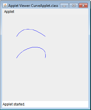
How It Works
To display the curves, you need an object of your own class type so that you can implement the paint() method for it. You define the inner class, CurvePane, for this purpose with JComponent as the base class so it is a Swing component. You create an object of this class (which is a member of the CurveApplet class) and add it to the content pane for the applet using its inherited add() method. The layout manager for the content pane is BorderLayout, and the default positioning is BorderLayout.CENTER so the CurvePane object fills the content pane.
The points defining the quadratic and cubic curves are defined as fields in the CurveApplet class and the fields that store references to the curve objects are used in the paint() method for the CurvePane class to display curves. The fields that store points are used in the CurvePane class constructor to create the objects encapsulating curves. You draw the curves in the paint() method by calling the draw() method for the Graphics2D object and passing a reference to a curve object as the argument. The classes that define curves implement the Shape interface so any curve object can be passed to the draw() method that has a parameter of type Shape.
It’s hard to see how the control points affect the shape of the curve, so let’s add some code to draw the control points.
TRY IT OUT: Displaying the Control Points
You can mark the position of each control point by drawing a small circle around it that I’ll call a marker. You will be able to move a control point around by dragging the marker with the mouse and see the effect on the curve. You can define a marker using an inner class of CurveApplet that you can define as follows:
  // Inner class defining a control point marker
  private class Marker {
    public Marker(Point2D.Double control)  {
      center = control;                  // Save control point as circle center

      // Create circle around control point
      circle = new Ellipse2D.Double(control.x-radius, control.y-radius,
                                    2.0*radius, 2.0*radius);
    }

      // Draw the marker
      public void draw(Graphics2D g2D) {
        g2D.draw(circle);
      }

     // Get center of marker - the control point position
      Point2D.Double getCenter() {
        return center;
    }

    Ellipse2D.Double circle;             // Circle around control point
    Point2D.Double center;               // Circle center - the control point
    static final double radius = 3;       // Radius of circle
  }
Directory "CurveApplet 2 displaying control points"
The argument to the constructor is the control point that is to be marked. The constructor stores this control point in the member center and creates an Ellipse2D.Double object that is the circle to mark the control point. The class also has a method, draw(), to draw the marker using the Graphics2D object reference that is passed to it, so Marker objects can draw themselves, given a graphics context. The getCenter() method returns the center of the marker as a Point2D.Double reference. You use the getCenter() method when you draw tangent lines from the end points of a curve to the corresponding control points.
You can now add fields to the CurveApplet class to define the Marker objects for the control points. These definitions should follow the members that define the points:
   // Markers for control points
   private Marker ctrlQuad = new Marker(control);
   private Marker ctrlCubic1 = new Marker(controlStart);
   private Marker ctrlCubic2 = new Marker(controlEnd);
Directory "CurveApplet 2 displaying control points"
You can now add code to the paint() method for the CurvePane class to draw the markers and the tangents from the end points of the curve segments:
     @Override
     public void paint(Graphics g) {
      // Code to draw curves as before...
      // Create and draw the markers showing the control points
      g2D.setPaint(Color.red);                   // Set the color
      ctrlQuad.draw(g2D);
      ctrlCubic1.draw(g2D);
      ctrlCubic2.draw(g2D);
      // Draw tangents from the curve end points to the control marker centers
      Line2D.Double tangent = new Line2D.Double(startQ, ctrlQuad.getCenter());
      g2D.draw(tangent);
      tangent = new Line2D.Double(endQ, ctrlQuad.getCenter());
      g2D.draw(tangent);

      tangent = new Line2D.Double(startC, ctrlCubic1.getCenter());
      g2D.draw(tangent);
      tangent = new Line2D.Double(endC, ctrlCubic2.getCenter());
      g2D.draw(tangent);
    }
Directory "CurveApplet 2 displaying control points"
If you recompile the applet with these changes, when you execute it again you should see the window shown in Figure 19-14.

How It Works
In the Marker class constructor, the top-left corner of the rectangle enclosing the circle for a control point is obtained by subtracting the radius from the x and y coordinates of the control point. You then create an Ellipse2D.Double object with the width and height as twice the value of radius — which is the diameter of the circle.
In the paint() method, you call the draw() method for each of the Marker objects to draw a red circle around each control point. The tangents to the curves are just lines from the end points of each curve segment to the centers of the corresponding Marker objects.
It would be good to see what happens to a curve segment when you move the control points around. Then you could really see how the control points affect the shape of the curve. That’s not as difficult to implement as it might sound, so let’s give it a try.
TRY IT OUT: Moving the Control Points
You arrange to allow a control point to be moved by positioning the cursor on it, pressing a mouse button, and dragging it around. Releasing the mouse button stops the process for that control point, so the user then is free to manipulate another control point. To implement this functionality in the applet you add another inner class to CurveApplet that handles mouse events:
private class MouseHandler extends MouseInputAdapter {
  @Override
  public void mousePressed(MouseEvent e) {
    // Check if the cursor is inside any marker
    if(ctrlQuad.contains(e.getX(), e.getY())) {
      selected = ctrlQuad;
    }
    else if(ctrlCubic1.contains(e.getX(), e.getY())) {
      selected = ctrlCubic1;
    }
    else if(ctrlCubic2.contains(e.getX(), e.getY())) {
      selected = ctrlCubic2;
    }
  }

  @Override
  public void mouseReleased(MouseEvent e) {
    selected = null;                            // Deselect any selected marker
  }

  @Override
  public void mouseDragged(MouseEvent e) {
    if(selected != null) {                      // If a marker is selected
      // Set the marker to current cursor position
      selected.setLocation(e.getX(), e.getY());
      pane.repaint();                           // Redraw pane contents
    }
  }

  private Marker selected;                      // Stores reference to selected marker
}
Directory "CurveApplet 3 moving the control points"
You need to add two import statements to the beginning of the source file, one because you reference the MouseInputAdapter class and the other because you refer to the MouseEvent class:
import javax.swing.event.MouseInputAdapter;
import java.awt.event.MouseEvent;
Directory "CurveApplet 3 moving the control points"
The mousePressed() method calls a contains() method for a Marker that should test whether the point defined by the arguments is inside the marker. You can implement this in the Marker class like this:
    // Test if a point x,y is inside the marker
    public boolean contains(double x, double y) {
      return circle.contains(x,y);
    }
Directory "CurveApplet 3 moving the control points"
This just calls the contains() method for the circle object that is the marker. This returns true if the point (x,y) is inside the circle, and false if it isn’t.
The mouseDragged() method calls a setLocation() method for the selected Marker object that is supposed to move the marker to a new position, so you need to implement this in the Marker class, too:
    // Sets a new control point location
    public void setLocation(double x, double y) {
      center.x = x;                      // Update control point
      center.y = y;                      // coordinates
      circle.x = x-radius;               // Change circle position
      circle.y = y-radius;               // correspondingly
    }
Directory "CurveApplet 3 moving the control points"
After updating the coordinates of the point center, you also update the position of the circle by setting its data member directly. You can do this because x and y are public members of the Ellipse2D.Double class and store the coordinates of the center of the ellipse.
You can create a MouseHandler object in the init() method for the applet and set it as the listener for mouse events for the pane object:
@Override
public void init() {
  pane = new CurvePane();                   // Create pane containing curves
  Container content = getContentPane();     // Get the content pane

  // Add the pane displaying the curves to the content pane for the applet
  content.add(pane);                 // BorderLayout.CENTER is default position

  MouseHandler handler = new MouseHandler();    // Create the listener
  pane.addMouseListener(handler);               // Monitor mouse button presses
  pane.addMouseMotionListener(handler);         // as well as movement
}
Directory "CurveApplet 3 moving the control points"
Of course, to make the effect of moving the control points apparent, you must update the curve objects before you draw them. You can add the following code to the paint() method to do this:
  @Override
  public void paint(Graphics g) {
    Graphics2D g2D = (Graphics2D)g;                  // Get a 2D device context

    // Update the curves with the current control point positions
    quadCurve.ctrlx = ctrlQuad.getCenter().x;
    quadCurve.ctrly = ctrlQuad.getCenter().y;
    cubicCurve.ctrlx1 = ctrlCubic1.getCenter().x;
    cubicCurve.ctrly1 = ctrlCubic1.getCenter().y;
    cubicCurve.ctrlx2 = ctrlCubic2.getCenter().x;
    cubicCurve.ctrly2 = ctrlCubic2.getCenter().y;
    // Rest of the method as before...
Directory "CurveApplet 3 moving the control points"
You can update the data members that store the control point coordinates for the curves directly because they are public members of each curve class. You get the coordinates of the new positions for the control points from their markers by calling the getCenter() method for each Marker object. You can then use the appropriate data member of the Point2D.Double object that is returned to update the fields for the curve objects.
If you recompile the applet with these changes and run it again you should get something like the window shown in Figure 19-15.

You should be able to drag the control points around with the mouse and see the curves change shape. If you find it’s a bit difficult to select the control points, just make the value of radius a bit larger. Note how the angle of the tangent as well as its length affects the shape of the curve.
How It Works
The mousePressed() method in the MouseHandler class is called when you press a mouse button. In this method you check whether the current cursor position is within any of the markers enclosing the control points. You do this by calling the contains() method for each Marker object and passing the coordinates of the cursor position to it. The getX() and getY() methods for the MouseEvent object supply the coordinates of the current cursor position. If one of the markers does enclose the cursor, you store a reference to the Marker object in the selected member of the MouseHandler class for use by the mouseDragged() method.
In the mouseDragged() method, you set the location for the Marker object referenced by selected to the current cursor position, and call repaint() for the pane object. The repaint() method causes the paint() method to be called for the component, so everything is redrawn, taking account of the modified control point position.
Releasing the mouse button causes the mouseReleased() method to be called. In here you just set the selected field back to null so no Marker object is selected. Remarkably easy, wasn’t it?
Complex Paths
You can define a more complex geometric shape as an object of type GeneralPath. A GeneralPath object can be a composite of lines, Quad2D curves, and Cubic2D curves, or even other GeneralPath objects.
In general, closed shapes such as rectangles and ellipses can be filled with a color or pattern quite easily because they consist of a closed path enclosing a region. In this case, whether a given point is inside or outside a shape can be determined quite simply. With more complex shapes such as those defined by a GeneralPath object, it can be more difficult. Such paths may be defined by an exterior bounding path that encloses interior “holes," and the “holes" may also enclose further interior paths. Therefore, it is not necessarily obvious whether a given point is inside or outside a complex shape. In these situations, the determination of whether a point is inside or outside a shape is made by applying a winding rule. When you create a GeneralPath object, you have the option of defining one of two winding rules that are then used to determine whether a given point is inside or outside the shape. The winding rules that you can specify are defined by static constants that are inherited in the GeneralPath class from Path2D:
- WIND_EVEN_ODD: A point is interior to a GeneralPath object if the boundary is crossed an odd number of times by a line from a point exterior to the GeneralPath to the point in question. When you use this winding rule for shapes with holes, a point is determined to be interior to the shape if it is enclosed by an odd number of boundaries.
- WIND_NON_ZERO: Whether a point is inside or outside a path is determined by considering how the path boundaries cross a line drawn from the point in question to infinity, taking account of the direction in which the path boundaries are drawn.
Looking along the line from the point, the point is interior to the GeneralPath object if the difference between the number of times the line is crossed by a boundary from left to right, and the number of times the line is crossed from right to left, is non-zero. When you use this rule for shapes bounded by more than one contiguous path — with holes, in other words — the result varies depending on the direction in which each path is drawn. If an interior path is drawn in the opposite direction to the outer path, the interior of the inner path is determined as not being interior to the shape.
The way these winding rules affect the filling of a complex shape is illustrated in Figure 19-16.
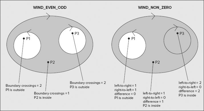
The region of the shape that is determined as being inside the shape is shown shaded in Figure 19-16. The directions in which the boundaries are drawn are indicated by the arrows on the boundaries. As you can see, the region where P3 lies is determined as being outside the shape by the WIND_EVEN_ODD rule, and as being inside the shape by the WIND_NON_ZERO rule.
You have four constructors available for creating GeneralPath objects:
- GeneralPath(): Defines a general path with a default winding rule of WIND_NON_ZERO.
- GeneralPath(int rule): Creates an object with the winding rule specified by the argument. You can specify the argument as WIND_NON_ZERO or WIND_EVEN_ODD.
- GeneralPath(int rule, int capacity): Creates an object with the winding rule specified by the first argument and the number of path segments specified by the second argument. In any event, the capacity is increased when necessary.
- GeneralPath(Shape shape): Creates an object from the Shape object that is passed as the argument.
You can create a GeneralPath object with the following statement:
GeneralPath p = new GeneralPath(GeneralPath.WIND_EVEN_ODD);
A GeneralPath object embodies the notion of a current point of type Point2D from which the next path segment is drawn. You set the initial current point by passing a pair of (x,y) coordinates as values of type float to the moveTo() method for the GeneralPath object. For example, for the object generated by the previous statement, you could set the current point with the following statement:
p.moveTo(10.0f,10.0f); // Set the current point to 10,10
When you add a segment to a general path, the segment is added starting at the current point, and the end of the segment becomes the new current point that is used as the starting point for the next segment. Of course, if you want disconnected segments in a path, you can call moveTo() to move the current point to wherever you want before you add a new segment. If you need to get the current position at any time, you can call the getCurrentPoint() method that returns it as a reference of type Point2D.
You can use the following methods to add segments to a GeneralPath object:
- void lineTo(float x, float y): Draws a line from the current point to the point (x, y).
- void quadTo(float ctrlx, float ctrly, float x2, float y2): Draws a quadratic curve segment from the current point to the point (x2, y2) with (ctrlx, ctrly) as the control point.
- void curveTo(float ctrlx1, float ctrly1, float ctrlx2, float ctrly2, float x2, float y2): Draws a Bezier curve segment from the current point with control point (ctrlx1, ctrly1) to (x2, y2) with (ctrlx2, ctrly2) as the control point.
Each of these methods updates the current point to be the end of the segment that is added. A path can consist of several subpaths because a new subpath is started by a moveTo() call. The closePath() method closes the current subpath by connecting the current point at the end of the last segment to the point defined by the previous moveTo() call.
I can illustrate how this works with a simple example. You could create a triangle with the following statements:
GeneralPath p = new GeneralPath(GeneralPath.WIND_EVEN_ODD);
p.moveTo(50.0f, 50.0f);                      // Start point for path
p.lineTo(150.0f, 50.0f);                     // Line from 50,50 to 150,50
p.lineTo(150.0f, 250.0f);                    // Line from 150,50 to 150,250
p.closePath();                               // Line from 150,250 back to start
The first line segment starts at the current position set by the moveTo() call. Each subsequent segment begins at the end point of the previous segment. The closePath() call joins the latest end point to the point set by the previous moveTo() call — which in this case is the beginning of the path. The process is much the same using quadTo() or curveTo() method calls, and of course you can intermix them in any sequence you like. You can remove all the segments in a path by calling the reset() method for the GeneralPath object. This empties the path.
The GeneralPath class implements the Shape interface, so a Graphics2D object knows how to draw a path. You just pass a reference to a GeneralPath object as the argument to the draw() method for the graphics context. To draw the path, p, that was defined in the preceding example in the graphics context g2D, you would write the following:
g2D.draw(p); // Draw path p
Let’s try an example.
TRY IT OUT: Reaching for the Stars
You won’t usually want to construct a GeneralPath object as I did in the preceding example. You probably want to create a particular shape — a triangle or a star, say — and then draw it at various points on a component. You might think you can do this by subclassing GeneralPath, but the GeneralPath class is declared as final so subclassing is not allowed. However, you can always add a GeneralPath object as a member of your class. You can try drawing some stars using your own Star class. You’ll use a GeneralPath object to create the star shown in Figure 19-17.

Here’s the code for a class that can create a path for a star:
import java.awt.geom.*;

public class Star {
  // Return a path for a star at x,y
  public static GeneralPath starAt(float x, float y) {
    Point2D.Float point = new Point2D.Float(x, y);
    p = new GeneralPath(GeneralPath.WIND_NON_ZERO);
    p.moveTo(point.x, point.y);
    p.lineTo(point.x + 20.0f, point.y - 5.0f);          // Line from start to A
    point = (Point2D.Float)p.getCurrentPoint();
    p.lineTo(point.x + 5.0f, point.y - 20.0f);          // Line from A to B
    point = (Point2D.Float)p.getCurrentPoint();
    p.lineTo(point.x + 5.0f, point.y + 20.0f);          // Line from B to C
    point = (Point2D.Float)p.getCurrentPoint();
    p.lineTo(point.x + 20.0f, point.y + 5.0f);          // Line from C to D
    point = (Point2D.Float)p.getCurrentPoint();
    p.lineTo(point.x - 20.0f, point.y + 5.0f);          // Line from D to E
    point = (Point2D.Float)p.getCurrentPoint();
    p.lineTo(point.x - 5.0f, point.y + 20.0f);          // Line from E to F
    point = (Point2D.Float)p.getCurrentPoint();
    p.lineTo(point.x - 5.0f, point.y - 20.0f);          // Line from F to g
    p.closePath();                                      // Line from G to start
    return p;                                           // Return the path
  }

  private static GeneralPath p;                         // Star path
}
Directory "StarApplet 1"
You can now define an applet that draw stars:
import javax.swing.*;
import java.awt.*;

@SuppressWarnings("serial")
public class StarApplet extends JApplet {
  // Initialize the applet
  @Override
  public void init() {
    StarPane pane = new StarPane();  // Pane containing stars
    getContentPane().add(pane);      // BorderLayout.CENTER is default position
  }

  // Class defining a pane on which to draw
  class StarPane extends JComponent {
    @Override
    public void paint(Graphics g) {
      Graphics2D g2D = (Graphics2D)g;
      float delta = 60f;                         // Increment between stars
      float starty = 0f;                         // Starting y position

      // Draw 3 rows of stars
      for(int yCount = 0; yCount < 3; yCount++) {
        starty += delta;                        // Increment row position
        float startx = 0f;                       // Start x position in a row

        // Draw a row of 4 stars
        for(int xCount = 0; xCount<4; xCount++) {
          g2D.draw(Star.starAt(startx += delta, starty));
        }
      }
    }
  }
}
Directory "StarApplet 1"
The HTML file for this applet could contain:
<html>
  <head>
  </head>
  <body bgcolor="000000">
    <center>
      <applet
        code = "StarApplet.class"
        width = "360"
        height = "240"
        >
      </applet>
    </center>
  </body>
</html>
This is large enough to accommodate our stars. If you compile and run the applet, you should see the Applet Viewer window shown in Figure 19-18.
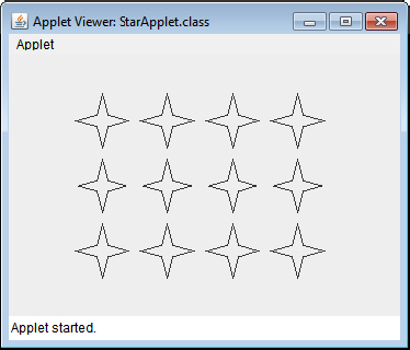
How It Works
The Star class has a GeneralPath object, p, as a static member that references the path for a star. There’s no need to create Star objects as all we are interested in is the path to draw a star.
The static starAt() method creates the path for a star at the position point that is defined by the arguments. The first line is drawn relative to the start point that is set by the call to moveTo() for p. For each subsequent line, you retrieve the current position by calling getCurrentPoint() for p and drawing the line relative to that. The last line to complete the star is drawn by calling closePath(). A reference to the GeneralPath object, p, that results is returned.
The StarApplet class draws stars on a component defined by the inner class StarPane. You draw the stars using the paint() method for the StarPane object, which is a member of the StarApplet class. Each star is drawn in the nested loop with the position specified by (x,y). The y coordinate defines the vertical position of a row, so this is incremented by delta on each iteration of the outer loop. The coordinate x is the position of a star within a row so this is incremented by delta on each iteration of the inner loop.
After you know how to create and draw a shape, filling it is easy. You just call the fill() method for the Graphics2D object and pass a reference of type Shape to it. This works for any shape, but for sensible results the boundary should be closed. The way the enclosed region is filled is determined by the window rule in effect for the shape.
Let’s try it out by modifying the applet example that displayed stars.
TRY IT OUT: Filling Stars
To fill the stars you just need to call the fill() method for each star in the paint() method of the StarPane object. Modify the paint() method as follows:
    @Override
    public void paint(Graphics g) {
      Graphics2D g2D = (Graphics2D)g;
      float delta = 60;                            // Increment between stars
      float starty = 0;                            // Starting y position

      // Draw 3 rows of 4 stars
      GeneralPath star = null;
      for(int yCount = 0 ; yCount<3; yCount++) {
        starty += delta;                           // Increment row position
        float startx = 0;                          // Start x position in a row

        // Draw a row of 4 stars
        for(int xCount = 0 ; xCount<4; xCount++) {
          star = Star.starAt(startx += delta, starty);
          g2D.setPaint(Color.GREEN);            // Color for fill is green
          g2D.fill(star);                        // Fill the star
          g2D.setPaint(Color.BLUE);             // Drawing color blue
          g2D.draw(star);
        }
      }
    }
Directory "StarApplet 2 filled stars"
You also need an import statement for the GeneralPath class name in the StarApplet.java source file:
import java.awt.geom.GeneralPath;
Now the applet window looks something like that shown in Figure 19-19, but in color, of course.


How It Works
You set the color for drawing and filling the stars differently, simply to show that you can get the outline as well as the fill. The stars are displayed in green with a blue boundary. It is important to draw the outline after the fill, otherwise the fill might encroach on the outline. You can fill a shape without drawing a boundary for it — just call the fill() method. You could amend the example to do this by deleting the last two statements in the inner loop. Now all you get is the green fill for each shape — no outline.
Gradient Fill
You are not limited to filling a shape with a uniform color. You can create a java.awt.GradientPaint object that represents a graduation in shade from one color to another and pass that to the setPaint() method for the graphics context. There are four GradientPaint class constructors:
- GradientPaint(Point2D p1, Color c1, Point2D p2, Color c2)
Defines a gradient from point p1 with the color c1 to the point p2 with the color c2. The color varies linearly from color c1 at point p1 to color c2 at point p2
- GradientPaint(float x1, float y1, Color c1, float x2, float y2, Color c2)
By default the gradient is acyclic, which means the color variation applies only between the two points. Beyond either end of the line the color is the same as the nearest end point.
- GradientPaint(Point2D p1, Color c1, Point2D p2, Color c2, boolean cyclic)
This does same as the previous constructor but with the points specified by their coordinates. With cyclic specified as false, this is identical to the first constructor. If you specify cyclic as true, the color gradation repeats cyclically off either end of the line — that is, you get repetitions of the color gradient in both directions.
- GradientPaint(float x1, float y1,Color c1, float x2, float y2,Color c2, boolean cyclic)
This is the same as the previous constructor except for the explicit point coordinates.
Points that are off the line defining the color gradient have the same color as the normal (that is, right-angle) projection of the point onto the line. This stuff is easier to demonstrate than to describe, so Figure 19-20 shows the output from the example you’re going to try out next.

You can see that points along lines at right angles to the line defined by p1 and p2 have the same color as the point on the line. The window shows both cyclic and acyclic gradient fill.
TRY IT OUT: Color Gradients
You will create an example similar to the star applet except that the applet draws rectangles with GradientPaint fills. Here’s the complete code:
import javax.swing.*;
import java.awt.*;
import java.awt.geom.*;

@SuppressWarnings("serial")
public class GradientApplet extends JApplet {
  // Initialize the applet
  @Override
  public void init() {
    GradientPane pane = new GradientPane(); // Pane contains filled rectangles
    getContentPane().add(pane);             // BorderLayout.CENTER is default position
  }

  // Class defining a pane on which to draw
  class GradientPane extends JComponent {
    @Override
    public void paint(Graphics g) {
      Graphics2D g2D = (Graphics2D)g;

      Point2D.Float p1 = new Point2D.Float(150.f, 75.f); // Gradient line start
      Point2D.Float p2 = new Point2D.Float(250.f, 75.f); // Gradient line end
      float width = 300;
      float height = 50;
      GradientPaint g1 = new GradientPaint(p1, Color.WHITE,
                                           p2, Color.DARK_GRAY,
                                           true);        // Cyclic gradient
      Rectangle2D.Float rect1 = new Rectangle2D.Float(p1.x-100, p1.y-25, width,height);
      g2D.setPaint(g1);                                  // Gradient color fill
      g2D.fill(rect1);                                    // Fill the rectangle
      g2D.setPaint(Color.BLACK);                         // Outline in black
      g2D.draw(rect1);                                   // Fill the rectangle
      g2D.draw(new Line2D.Float(p1, p2));
      g2D.drawString("Cyclic Gradient Paint", p1.x-100, p1.y-50);
      g2D.drawString("p1", p1.x-20, p1.y);
      g2D.drawString("p2", p2.x+10, p2.y);

      p1.setLocation(150, 200);
      p2.setLocation(250, 200);
      GradientPaint g2 = new GradientPaint(p1, Color.WHITE,
                                           p2, Color.DARK_GRAY,
                                           false);       // Acyclic gradient
      rect1.setRect(p1.x-100, p1.y-25, width, height);
      g2D.setPaint(g2);                                  // Gradient color fill
      g2D.fill(rect1);                                    // Fill the rectangle
      g2D.setPaint(Color.BLACK);                         // Outline in black
      g2D.draw(rect1);                                   // Fill the rectangle
      g2D.draw(new Line2D.Float(p1, p2));
      g2D.drawString("Acyclic Gradient Paint", p1.x-100, p1.y-50);
      g2D.drawString("p1", p1.x-20, p1.y);
      g2D.drawString("p2", p2.x+10, p2.y);

    }

  }
}
Directory "GradientApplet 1"
If you run this applet with the following HTML, you should get the window previously shown in Figure 19-20:
<html>
  <head>
  </head>
  <body bgcolor="000000">
    <center>
      <applet
        code = "GradientApplet.class"
        width = "400"
        height = "280"
        >
      </applet>
    </center>
  </body>
</html>
Note that to get a nice smooth color gradation, your monitor needs to be set up for at least 16-bit colors (65536 colors), and preferably 24-bit colors (16.7 million colors).
How It Works
The applet displays two rectangles, and they are annotated to indicate which is which. The applet also displays the gradient lines, which lie in the middle of the rectangles. You can see the cyclic and acyclic gradients quite clearly. You can also see how points off the gradient line have the same color as the normal projection onto the line.
The first block of code in the paint() method creates the upper rectangle where the GradientPaint object that is used is g1. This is created as a cyclic gradient between the points p1 and p2, and varying from white to dark gray. I chose these shades because the book is printed in black and white, but you can try the example with any color combination you like. To set the color gradient for the fill, you call setPaint() for the Graphics2D object and pass g1 to it. Any shapes that are drawn and/or filled subsequent to this call use the gradient color, but here you just fill the rectangle, rect1.
To make the outline and the annotation clearer, you set the current color back to black before calling the draw() method to draw the outline of the rectangle and the drawString() method to annotate it.
The code for the lower rectangle is essentially the same as that for the first. The only important difference is that you specify the last argument to the constructor as false to get an acyclic gradient fill pattern. This causes the colors of the ends of the gradient line to be the same as the end points. You could have omitted the boolean parameter here, getting an acyclic gradient by default.
The applet shows how points off the gradient line have the same color as the normal projection onto the line. This is always the case, regardless of the orientation of the gradient line. You could try changing the definition of g1 for the upper rectangle to:
GradientPaint g1 = new GradientPaint(p1.x, p1.y - 20, Color.WHITE,
                                     p2.x, p2.y + 20, Color.DARK_GRAY,
                                     true);               // Cyclic gradient
You also need to draw the gradient line in its new orientation:
g2D.draw(rect1);                                      // Fill the rectangle
//g2D.draw(new Line2D.Float(p1, p2));
g2D.draw(new Line2D.Float(p1.x, p1.y - 20, p2.x, p2.y + 20));
The annotation for the end points also have to be moved:
g2D.drawString("p1",p1.x - 20,p1.y - 20);
g2D.drawString("p2",p2.x + 10,p2.y + 20);
If you run the applet with these changes, you can see in Figure 19-21 how the gradient is tilted and how the color of a point off the gradient line matches that of the point that is the orthogonal projection onto it.

When you create shapes in Sketcher, you have no idea of the sequence of shape types that will occur. This is determined totally by the person using the program to produce a sketch. You therefore need to be able to draw shapes and perform other operations on them without knowing what they are — and of course polymorphism can help here.
You don’t want to use the shape classes defined in java.awt.geom directly because you want to add your own attributes such as color or line style for the shapes and store them as part of your shape objects. You could consider using the shape classes as base classes for your shapes, but you couldn’t use the GeneralPath class in this scheme of things because, as I said earlier, the class has been defined as final and therefore cannot be subclassed. You could define an interface that all your shape classes would implement. However, some methods have a common implementation in all your shape classes, which would mean that you would need to repeat this code in every class.
Taking all of this into account, the easiest approach might be to define a common base class for the Sketcher shape classes and include a member in each class to store a java.awt.geom shape object of one kind or another. You are then able to store a reference to any of your shape class objects as the base class type and get polymorphic behavior.
You can start by defining a base class, Element, from which you derive the classes defining specific types of shapes for Sketcher. The Element class has data members that are common to all your shape types, and contains all the methods that you want to be able to execute polymorphically. Each shape class that is derived from the Element class might need its own implementation of some or all of these methods.
Figure 19-22 shows the initial members that you define in the Element base class. The class is serializable because you want to write a sketch to a file eventually. There are three fields: the color member to store the color of a shape, the position member to store the location of a shape, and the serialVersionUID member for serialization. The getBounds() method returns a rectangle that completely encloses the element. This is for use in paint operations. The draw() method draws an element. The getBounds() and draw() methods are abstract here because the Element class is not intended to define a shape. They need to be included in the Element class to be able to call them polymorphically for derived class objects. You can implement the getColor() and getPosition() methods in this class though.
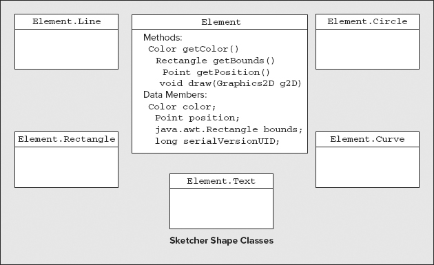
Initially, you define the five classes shown Figure 19-22 that represent shapes, with the Element class as a base. They provide objects that represent straight lines, rectangles, circles, freehand curves, and blocks of text. These classes inherit the fields that you define for the Element class and they are serializable.
As you can see from the names of the Sketcher shape classes in Figure 19-22, they are all nested classes to the Element class. The Element class serves as the base class, as well as housing the shape classes. This helps to avoid any possible confusion with other classes in the Java libraries that might have the same names. Because there are no Element objects around, you declare the inner shape classes as static members of the Element class.
You can now define the base class, Element. This won’t be the final version because you will add more functionality in later chapters. Here’s the code for Element.java:
import java.awt.*;
import java.io.Serializable;

public abstract class Element implements Serializable {
  protected Element(Point position, Color color) {
    this.position = position;
    this.color = color;
  }

  public Color getColor() {
    return color;
  }

  public Point getPosition() {
    return position;
  }

  public java.awt.Rectangle getBounds() {
    return bounds;
  }

  public abstract void draw(Graphics2D g2D);
  public abstract void modify(Point start, Point last);

  protected Point position;                             // Position of a shape
  protected Color color;                                // Color of a shape
  protected java.awt.Rectangle bounds;                  // Bounding rectangle
  private final static long serialVersionUID = 1001L;
}
Directory "Sketcher 4 drawing sketch line and rectangle elements"
Put this file in the same directory as Sketcher.java. You have defined a constructor to initialize the color and position data member and the get methods to provide access to these. The bounds member is created by the subclasses and it also has a get method. The member and return type must be qualified by the package name to distinguish it from the inner class type Rectangle. The constructor is protected because it is only called by inner class constructors.
The return type for the getBounds() method that makes the bounding rectangle for an element available is fully qualified by the package name. This is to avoid confusion with your own Rectangle class that you add as an inner class later in this chapter.
There are two abstract methods that must be implemented by the subclasses. This means that the Element class must be declared as abstract. An implementation of the draw() method draws an element using the Graphics2D object that is passed to it. The modify() method alters the definition of an element using the Point objects that are passed to it as defining points.
Storing Shapes in the Model
Even though you haven’t defined the classes for the shapes that Sketcher creates, you can implement the mechanism for storing them in the SketcherModel class. You’ll store all of them as objects of type Element, so you can use a LinkedList<Element> collection class object to hold an arbitrary number of Element objects. The container for Element references needs to allow deletion as well as additions to the contents, and you will want to remove items and rearrange the order of items, too. This makes a linked list the best choice. A map container just doesn’t apply to Sketcher data. An ArrayList<> or a Vector<> container doesn’t really fit the bill. Neither is it very efficient when you want to remove items on a regular basis whereas deleting a shape from a linked list is fast.
You can add a member to the SketcherModel class that you defined earlier in the Sketcher program to store elements:
import java.io.Serializable;
import java.util.*;

public class SketcherModel extends Observable implements Serializable {
  // Detail of the rest of class to be filled in later...
  protected LinkedList<Element> elements = new LinkedList<>();
  private final static long serialVersionUID = 1001L;
}
You definitely want methods to add and delete Element objects. It is also very useful if the SketcherModel class implements the Iterable<Element> interface because that allows a collection-based for loop to be used to iterate over the Element objects stored in the model. Here’s how the class looks to accommodate that:
import java.io.Serializable;
import java.util.*;

public class SketcherModel extends Observable
                                   implements Serializable, Iterable<Element> {
  //Remove an element from the sketch
  public boolean remove(Element element) {
    boolean removed = elements.remove(element);
    if(removed) {
      setChanged();
      notifyObservers(element.getBounds());
    }
    return removed;
  }

  //Add an element to the sketch
  public void add(Element element) {
    elements.add(element);
    setChanged();
    notifyObservers(element.getBounds());
  }

  // Get iterator for sketch elements
  public Iterator<Element> iterator() {
    return elements.iterator();
  }

  protected LinkedList<Element> elements = new LinkedList< >();
  private final static long serialVersionUID = 1001L;
}
Directory "Sketcher 4 drawing sketch line and rectangle elements"
All three methods make use of methods that are defined for the LinkedList<Element> object, elements, so they are very simple. When you add or remove an element, the model is changed, so you call the setChanged() method inherited from Observable to record the change and the notifyObservers() method to communicate this to any observers that have been registered with the model. The observers are the views that display the sketch. You pass the java.awt.Rectangle object that is returned by getBounds() for the element to notifyObservers(). Each of the shape classes defined in the java.awt.geom package implements the getBounds() method to return the rectangle that bounds the shape. You are able to use this in the view to specify the area that needs to be redrawn.
In the remove() method, it is possible that the element was not removed — because it was not there, for example — so you test the boolean value that is returned by the remove() method for the LinkedList<Element> object. You also return this value from the remove() method in the SketcherModel class, as the caller may want to know if an element was removed or not.
The iterator() method returns an iterator of type Iterator<Element> for the linked list that holds the elements in the sketch. This can be used to iterate over all the elements in a sketch. It also allows an element to be removed using the remove() method that is declared in the Iterator<> interface.
Even though you haven’t defined any of the element classes that Sketcher supports, you can still make provision for displaying them in the view class.
Drawing Shapes
You draw the shapes in the paint() method for the SketcherView class, so if you haven’t already done so, remove the old code from the paint() method now. You can replace it with code for drawing Sketcher shapes like this:
import javax.swing.JComponent;
import java.util.*;
import java.awt.*;

class SketcherView extends JComponent implements Observer {
  public SketcherView(Sketcher theApp) {
    this.theApp = theApp;
  }

  // Method called by Observable object when it changes
  public void update(Observable o, Object rectangle) {
    // Code to respond to changes in the model...
  }

  @Override
  public void paint(Graphics g) {
    Graphics2D g2D = (Graphics2D)g;            // Get a 2D device context
    for(Element element: theApp.getModel()) {  // For each element in the model
      element.draw(g2D);                       // ...draw the element
    }
  }

  private Sketcher theApp;                         // The application object
}
Directory "Sketcher 4 drawing sketch line and rectangle elements"
The getModel() method that you implemented in the Sketcher class returns a reference to the SketcherModel object, and because SketcherModel implements the Iterable<> interface, you can use it in a collection-based for loop to iterate over all the Element objects in the sketch. For each element, you call its draw() method with g2D as the argument. This draws any type of element because the draw() method is polymorphic. In this way you draw all the elements that are stored in the model. You should be able to compile Sketcher successfully, even though the Element class does not have any inner classes defined for elements.
It’s time you put in place the mechanism for creating Sketcher elements. This determines the data that you use to define the location and dimensions of an element.
You’ve drawn shapes in examples just using data internal to a program so far. The Sketcher program must be able to draw a shape from user input and then store the finished shape in the model. You provide mechanisms for a user to draw any shape using the mouse.
Ideally, the process should be as natural as possible, so to achieve this you will allow a user to draw by pressing the left mouse button (more accurately, button 1 — if you have a left-handed setup for the mouse it is the right button, but still button 1) and dragging the cursor to draw the selected type of shape. So for a line, the point where you depress the mouse button is the start point for the line, and the point where you release the button is the end point. This process is illustrated in Figure 19-23.

As the user drags the mouse with the button down, Sketcher displays the line as it looks at that point. Thus, the line is displayed dynamically all the time the mouse cursor is being dragged with the left button pressed. This process is called rubber-banding.
You can use essentially the same process of pressing the mouse button and dragging the cursor for all four of the geometric shapes you saw when I discussed the Element class. Two points define a line, a rectangle, or a circle — the cursor position where the mouse button is pressed and the cursor position where the mouse button is released. For a line the two points are the end points, for a rectangle they are opposite corners, and for a circle they are the center and a point on the circumference. This implies that the constructors for these have three parameters, corresponding to the two points and the color. A curve is a little more complicated in that many more than two points are involved, so I’m deferring discussion of that until later.
All the operations that deal with the mouse in your program involve handling events that the mouse generates. Let’s look at how you handle mouse events to make drawing lines, rectangles, and circles work.
Handling Mouse Events
Because all the drawing operations for a sketch are accomplished using the mouse, you must implement the process for creating elements within the methods that handle the mouse events. The mouse events you’re interested in originate in the SketcherView object because the mouse events that relate to drawing shapes originate in the content pane for the application window, which is the view object. You make the view responsible for handling all its own events, which includes events that occur in the drawing process as well as interactions with existing shapes.
Drawing a shape, such as a line, interactively involves you in handling three different kinds of mouse event. Table 19-1 is a summary of what they are and what you need to do in Sketcher when they occur:
TABLE 19-1: Mouse Events for Drawing Shapes
| EVENT | ACTION |
| Button 1 Pressed | Save the cursor position somewhere as the starting point for the shape. This is the first point on a line, a corner of a rectangle, or the center of a circle. You store this in a data member of the inner class to SketcherView that you create to define listeners for mouse events. |
| Mouse Dragged | Save the current cursor position somewhere as the end point for a shape. This is the end of a line, the opposite corner of a rectangle, or a point on the circumference of a circle. Erase any previously drawn temporary shape, and create a new temporary shape from the starting point that was saved initially. Draw the new temporary shape. |
| Button 1 Released | If there’s a reference to a temporary shape stored, add it to the sketch model and redraw it. |
The shape that is created is determined by the value stored in the elementType member of the SketcherFrame class. The color of the shape is the color stored in the elementColor member. Both can be changed by the user at any time using the menu items and toolbar buttons you added in the previous chapter.
Remember from Chapter 18 that there are two mouse listener interfaces: MouseListener, which has methods for handling events that occur when any of the mouse buttons are pressed or released, and MouseMotionListener, which has methods for handling events that arise when the mouse is moved. Also recall that the MouseInputAdapter class implements both, and because you need to implement methods from both interfaces, you add an inner class to the SketcherView class that extends the MouseInputAdapter class.
Because there’s quite a lot of code involved in this, you first define the bare bones of the class to handle mouse events and then continue to add the detail incrementally until it does what you want.
Implementing a Mouse Listener
Add the following class outline as an inner class to SketcherView:
import javax.swing.JComponent;
import java.util.*;
import java.awt.*;
import java.awt.event.MouseEvent;
import javax.swing.event.MouseInputAdapter;

class SketcherView extends JComponent implements Observer {
  // Rest of the SketcherView class as before...

  class MouseHandler extends MouseInputAdapter {
    @Override
    public void mousePressed(MouseEvent e)  {
      // Code to handle mouse button press...
    }

    @Override
    public void mouseDragged(MouseEvent e) {
      // Code to handle the mouse being dragged...
    }

    @Override
    public void mouseReleased(MouseEvent e) {
      // Code to handle the mouse button being release...
    }

    private Point start;                     // Stores cursor position on press
    private Point last;                      // Stores cursor position on drag
    private Element tempElement;             // Stores a temporary element
  }
  private Sketcher theApp;                   // The application object
}
Directory "Sketcher 4 drawing sketch line and rectangle elements"
You have implemented the three methods that you need to create an element.
The mousePressed() method will store the position of the cursor in the start member of the MouseHandler class, so this point is available to the mouseDragged() method that is called repeatedly when you drag the mouse cursor with the button pressed.
The mouseDragged() method creates an element using the current cursor position together with the position previously saved in start. It stores a reference to the element in the tempElement member. The last member of the MouseHandler class is used to store the cursor position when mouseDragged() is called. Both start and last are of type Point because this is the type that you get for the cursor position, but remember that Point is a subclass of Point2D, so you can always cast a Point reference to Point2D when necessary.
The mouseReleased() method is called when you release the mouse button. This method stores the element in the sketch and cleans up where necessary.
An object of type MouseHandler is the listener for mouse events for the view object, so you can put this in place in the SketcherView constructor. Add the following code at the end of the existing code:
  public SketcherView(Sketcher theApp) {
    this.theApp = theApp;
    MouseHandler handler = new MouseHandler();     // create the mouse listener
    addMouseListener(handler);                     // Listen for button events
    addMouseMotionListener(handler);               // Listen for motion events
  }
Directory "Sketcher 4 drawing sketch line and rectangle elements"
You call the addMouseListener() and addMotionListener() methods and pass the same listener object as the argument to both because the MouseHandler class deals with both types of event. Both methods are inherited in the SketcherView class from the Component class, which also defines an addMouseWheelListener() method for when you want to handle mouse wheel events.
Let’s go for the detail of the MouseHandler class now, starting with the mousePressed() method.
Handling Mouse Button Press Events
First, you need to find out which button is pressed. It is generally a good idea to make mouse button operations specific to a particular button. That way you avoid potential confusion when you extend the code to support more functionality. The getButton() method for the MouseEvent object that is passed to a handler method returns a value of type int that indicates which of the three mouse buttons changed state. The value is one of four constants that are defined in the MouseEvent class:
BUTTON1 BUTTON2 BUTTON3 NOBUTTON
On a two-button mouse or a wheel mouse, BUTTON1 for a right-handed user corresponds to the left button and BUTTON2 corresponds to the right button. BUTTON3 corresponds to the middle button when there is one. NOBUTTON is the return value when no button has changed state.
You can record the button state in the handler object. First add a member to the MouseHandler class to store the button state:
private int buttonState = MouseEvent.NOBUTTON; // Records button state
You can record which button is pressed by using the following code in the mousePressed() method:
public void mousePressed(MouseEvent e) {
  buttonState = e.getButton();            // Record which button was pressed
  if(buttonState == MouseEvent.BUTTON1) {
    // Code to handle button 1 press...
  }
}
By recording the button state, you make it available to the mouseDragged() method. The button state won’t change during a mouse dragged event so if you don’t record it when the mouse pressed event occurs, the information about which button is pressed is lost.
The MouseEvent object that is passed to all mouse handler methods records the current cursor position, and you can get a Point reference to it by calling the getPoint() method for the object. For example:
public void mousePressed(MouseEvent e) {
  start = e.getPoint();                   // Save the cursor position in start
  buttonState = e.getButton();               // Record which button was pressed
  if(buttonState == MouseEvent.BUTTON1) {
    // Code to handle button 1 press...
  }
}
The mouseDragged() method is going to be called very frequently, and to implement rubber-banding of the element, the element must be redrawn each time so it needs to be very fast. You don’t want to have the whole view redrawn each time, as this carries a lot of overhead. You need an approach that redraws just the element.
Using XOR Mode
One way to implement rubber-banding is to draw in XOR mode. You set XOR mode by calling the setXORMode() method for a graphics context and passing a color to it — usually the background color. In this mode the pixels are not written directly to the screen. The color in which you are drawing is combined with the color of the pixel currently displayed together with a third color that you specify, by exclusive ORing them together, and the resultant pixel color is written to the screen. The third color is usually set to be the background color, so the color of the pixel that is written is the result of the following operation:
resultant_Color = foreground_color^background_color^current_color
If you remember the discussion of the exclusive OR operation back in Chapter 2, you realize that the effect of this is to flip between the drawing color and the background color. The first time you draw a shape, the result is in the current element color. When you draw the same shape a second time, the result is the background color so the shape disappears. Drawing a third time makes it reappear.
Based on the way XOR mode works, you can now implement the mousePressed() method for the MouseHander class like this:
public void mousePressed(MouseEvent e) {
      start = e.getPoint();                           // Save the cursor position in start
      buttonState = e.getButton();                    // Record which button was pressed
      if(buttonState == MouseEvent.BUTTON1) {
        g2D = (Graphics2D)getGraphics();          // Get graphics context
        g2D.setXORMode(getBackground());          // Set XOR mode
  }
}
The getGraphics() method that you call in this method is for the view object; the MouseHandler class has no such method. The method is inherited in the SketcherView class from the Component class. If button 1 was pressed, you obtain a graphics context for the view and store it in g2D, so you must add g2D as a field in the MouseHandler class:
private Graphics2D g2D = null; // Temporary graphics context
You pass the color returned by the getBackground() method for the view object to the setXORMode() method for g2D. This causes objects that you redraw in a given color to switch between the origin color and the background color. You are able to use this mode in the mouseDragged() method to erase a previously drawn shape.
With the code in place to handle a button pressed event, you can have a go at implementing mouseDragged().
Handling Mouse Dragged Events
You obtain the cursor position in the mouseDragged() method by calling getPoint() for the event object that is passed as the argument, so you could write:
last = e.getPoint(); // Get cursor position
But you want to handle drag events only for button 1, so you make this conditional upon the buttonState field having the value MouseEvent.BUTTON1.
When mouseDragged() is called for the first time, you won’t have created an element. In this case you can just create one from the points stored in start and last and then draw it using the graphics context saved by the mousePressed() method. The mouseDragged() method is called lots of times while you drag the mouse though, and for every occasion other than the first, you must redraw the old element so that you effectively erase it before creating and drawing the new one. Because the graphics context is in XOR mode, drawing the element a second time displays it in the background color, so it disappears from the view. Here’s how you can do all that:
    public void mouseDragged(MouseEvent e) {
      last = e.getPoint();                            // Save cursor position

      if(buttonState == MouseEvent.BUTTON1) {
        if(tempElement == null) {                     // Is there an element?
          tempElement = Element.createElement(        // No, so create one
                                 theApp.getWindow().getElementType(),
                                 theApp.getWindow().getElementColor(),
                                 start, last);
        } else {
          tempElement.draw(g2D);                      // Yes - draw to erase it
          tempElement.modify(start, last);            // Now modify it
        }
        tempElement.draw(g2D);                        // and draw it
      }
    }
Directory "Sketcher 4 drawing sketch line and rectangle elements"
This method is only called when a button is pressed, and if button 1 is pressed, you are interested. You first check for an existing element by comparing the reference in tempElement with null. If it is null, you create an element of the current type by calling a createElement() method that you will add to the Element class in a moment. You save a reference to the element that is created in the tempElement member of the listener object. You pass the element type and color to the createElement() method. You obtain these using the application object to access the application window so you can then call methods for the SketcherFrame object to retrieve them. These methods don’t exist in SketcherFrame yet, but it’s not difficult to implement them:
  // Return the current drawing color
  public Color getElementColor() {
    return elementColor;
  }

  // Return the current element type
  public int getElementType() {
    return elementType;
  }
Directory "Sketcher 4 drawing sketch line and rectangle elements"
If tempElement is not null in the mouseDragged() method, an element already exists, so you draw over it in the application window by calling its draw() method. Because you are in XOR mode, this effectively erases the element. You then modify the existing element to incorporate the latest cursor position by calling the method modify() for the element object. Finally, you draw the latest version of the element that is referenced by tempElement.
You can implement the createElement() method as a static member of the Element class. The parameters for the method are the current element type and color and the two points that are used to define each element. Here’s the code:
  public static Element createElement(int type, Color color, Point start, Point end) {
    switch(type) {
      case LINE:
        return new Line(start, end, color);
      case RECTANGLE:
         return new Rectangle(start, end, color);
      case CIRCLE:
        return new Circle(start, end, color);
      case CURVE:
        return new Curve(start, end, color);
      default:
       assert false;                     // We should never get to here
    }
    return null;
  }
Directory "Sketcher 4 drawing sketch line and rectangle elements"
Because you refer to the constants that identify element types here, you must import the static members of the SketcherConstants class that you defined in the Constants package into the SketcherView.java source file. Add the import statement to the Element class file:
import static Constants.SketcherConstants.*;
The createElement() method returns a reference to a shape as type Element. You determine the type of shape to create by retrieving the element type ID stored in the SketcherFrame class by the menu item listeners that you put together in the previous chapter.
The switch statement in the createElement() method selects the constructor to be called, and as you see, they are all essentially of the same form. If the code falls through the switch with an ID that you haven’t provided for, you return null. Of course, none of these shape class constructors exists in the Sketcher program yet, so if you want to try compiling the code you have so far, you need to comment out each of the return statements. Because you are calling the constructors from a static method in the Element class, the element classes must be static, too. You implement these very soon, but first let’s add the next piece of mouse event handling that’s required — handling button release events.
Handling Button Release Events
When the mouse button is released, you have created an element. In this case all you need to do is to add the element that is referenced by the tempElement member of the MouseHandler class to the SketcherModel object that represents the sketch. One thing you need to consider, though: someone might click the mouse button without dragging it. In this case there won’t be an element to store. In this case you just clean up the data members of the MouseHandler object:
    public void mouseReleased(MouseEvent e) {
      if(e.getButton() == MouseEvent.BUTTON1) {
        buttonState = MouseEvent.NOBUTTON;     // Reset the button state

        if(tempElement != null) {              // If there is an element...
          theApp.getModel().add(tempElement);  // ...add it to the model...
          tempElement = null;                  // ...and reset the field
        }
        if(g2D != null) {                      // If there's a graphics context
          g2D.dispose();                       // ...release the resource...
          g2D = null;                          // ...and reset field to null
        }
        start = last = null;                   // Remove any points
      }
    }
Directory "Sketcher 4 drawing sketch line and rectangle elements"
When button 1 for the mouse is released it changes state, so you can use the getButton() method here to verify that this occurred. Of course, once button 1 is released, you should reset buttonState.
If there is a reference stored in tempElement, you add it to the model by calling the add() method that you defined for the SketcherModel class and set tempElement back to null. It is most important that you set tempElement back to null here. Failing to do that would result in the old element reference being added to the model when you click the mouse button.
Another important operation that the mouseReleased() method carries out is to call the dispose() method for the g2D object. Every graphics context makes use of system resources. If you use a lot of graphics context objects and you don’t release the resources they use, your program consumes more and more resources. When you call dispose() for a graphics context object, it can no longer be used, so you set g2D back to null to be on the safe side.
When you add the new element to the model, the view is notified as an observer, so the update() method for the view object is called. You can implement the update() method in the SketcherView class like this:
  public void update(Observable o, Object rectangle) {
    if(rectangle != null) {
      repaint((Rectangle)rectangle);
    } else {
      repaint();
    }
  }
Directory "Sketcher 4 drawing sketch line and rectangle elements"
If the reference passed to update() is not null, then you have a reference to a Rectangle object that was provided by the notifyObservers() method call in the add() method for the SketcherModel object. This rectangle is the area occupied by the new element, so when you pass this to the repaint() method for the view object, just this area is added to the area to be redrawn on the next call of the paint() method. The rectangle needs to completely enclose what you want painted. In particular, points on the right and bottom boundaries of the rectangle are not included. If rectangle is null, you call the version of repaint() that has no parameter to redraw the whole view.
You have implemented the three methods that you need to draw shapes. You could try it out if only you had a shape to draw, but before I get into that I’m digressing briefly to introduce another class that you can use to get information about where the mouse cursor is. This is just so you know about this class. You aren’t using it in any examples.
Using MouseInfo Class Methods
The java.awt.MouseInfo class provides a way for you to get information about the mouse at any time. The MouseInfo class defines a static method, getPointerInfo(), that returns a reference to an object of type java.awt.PointerInfo, which encapsulates information about where the mouse cursor was when the method was called. To find the location of the mouse cursor from a PointerInfo object you call its getLocation() method. This method returns a reference to a Point object that identifies the mouse cursor location. Thus you can find out where the mouse cursor is at any time like this:
Point position = MouseInfo.getPointerInfo().getLocation();
After executing this code fragment, the position object contains the coordinates of the mouse cursor at the time you call the getPointerInfo() method. Note that the PointerInfo object that this method returns does not get updated when the mouse cursor is moved, so there’s no point in saving it. You must always call the getPointerInfo() method each time you want to find out where the cursor is.
When you have two or more display devices attached to your computer, you can find out which display the mouse cursor is on by calling the getDevice() method for the PointerInfo object. This returns a reference to a java.awt.GraphicsDevice object that encapsulates the display that shows the cursor.
The MouseInfo class also defines a static method getNumberOfButtons(), which returns a value of type int that specifies the number of buttons on the mouse. This is useful when you want to make your code adapt automatically to the number of buttons on the mouse. You can make your program take advantage of the second or third buttons on the mouse when they are present, and adapt to use alternative GUI mechanisms when they are not available — by using an existing mouse button combined with keyboard key presses to represent buttons that are absent, for example.
Most of the time you will want to find the cursor location from within a mouse event-handling method. In these cases you find it is easiest to obtain the mouse cursor location from the MouseEvent object that is passed to the method handling the event. However, when you don’t have a MouseEvent object available, you still have the MouseInfo class methods to fall back on.
Now, I return to the subject of how you can define shapes.
DEFINING YOUR OWN SHAPE CLASSES
All the classes that define shapes in Sketcher are static nested classes of the Element class. As I said earlier, as well as being a convenient way to keep the shape class definitions together, this also avoids possible conflicts with the names of standard classes such as the Rectangle class in the java.awt package.
It will be helpful later if each shape class defines a shape with its own origin, like a Swing component. The process for drawing a shape in a graphics context is to move the origin of the graphics context to the position recorded for the shape and then draw the shape relative to the new origin. You can start with the simplest type of Sketcher shape — a class representing a line.
Defining Lines
A line is defined by two points and its color. The origin is the first point on the line, so all line objects have their first point as (0,0). This is used in all the shape classes in Sketcher, so add a new member to the Element class:
static final Point origin = new Point();
The default constructor for Point creates a point at the origin.
You can define the Line class as a nested class in the base class Element as follows:
import java.awt.*;
import java.io.Serializable;
import static Constants.SketcherConstants.*;
import java.awt.geom.*;

public abstract class Element implements Serializable {
  // Code defining the base class...
  // Nested class defining a line
  public static class Line extends Element {
    public Line(Point start, Point end, Color color) {
      super(start, color);

      line = new Line2D.Double(origin.x,            origin.y,
                               end.x - position.x , end.y - position.y);
      bounds = new java.awt.Rectangle(
                     Math.min(start.x ,end.x),    Math.min(start.y, end.y),
                     Math.abs(start.x - end.x)+1, Math.abs(start.y - end.y)+1);
    }

    // Change the end point for the line
    public void modify(Point start, Point last) {
      line.x2 = last.x - position.x;
      line.y2 = last.y - position.y;
      bounds = new java.awt.Rectangle(
                   Math.min(start.x ,last.x),    Math.min(start.y, last.y),
                   Math.abs(start.x - last.x)+1, Math.abs(start.y - last.y)+1);
    }

    // Display the line
    public  void draw(Graphics2D g2D) {
     g2D.setPaint(color);                           // Set the line color
     g2D.translate(position);                       // Move origin
     g2D.draw(line);                                // Draw the line
     g2D.translate(-position.x, -position.y);       // Move context origin back
   }

    private Line2D.Double line;
    private final static long serialVersionUID = 1001L;
  }
  // Abstract methods & fields in Element class...
}
Directory "Sketcher 4 drawing sketch line and rectangle elements"
The Line constructor has three parameters: the two end points of the line as type Point and the color. You use type Point because all the points you work with originate from mouse events as type Point. Calling the base class constructor records the position and color of the line in the members of the Line class inherited from Element. You create the line shape as a Line2D.Double object in the Line class constructor using the Line2D.Double constructor that accepts the coordinates of the two points that define the line. You then store the reference in the line member of the class. The coordinates of the first point on the line is the origin point so you must adjust the coordinates of the second point to be relative to origin at (0,0). You can easily do this by subtracting the x and y coordinates of position from the corresponding coordinates of end.
The constructor creates the bounds rectangle from the two points that define the line. The position of the rectangle is the top-left corner. This is the point corresponding to the minimum x and minimum y of the two defining points. The rectangle width and height are the differences between the x and the y coordinates, respectively. However, when an area specified by a rectangle is painted, the pixels that lie on the right and bottom edges of the rectangle are not included. To ensure that the entire line lies within the rectangle you add 1 to the width and height.
The modify() method is called when an end point of the line changes when the mouse is being dragged to define the line. The end point of a Line2D.Double object is stored in its public members, x2 and y2. The modify() method updates these by subtracting the corresponding members of last to adjust for the first point being at origin. The method then updates the bounds member to accommodate the new end point.
The draw() method sets the line color in the device context by passing it to the setPaint() method and then moves the origin of the device context to position by calling its translate() method. It then draws a line relative to the new origin by calling draw() for the g2D object. You call translate() once more to reset the origin back to its original state at position. It is essential to do this because the mouseDragged() method executes many times and calls draw() using the same device context. If you don’t reset the origin for the device context, it is moved further and further each time you draw another instance of an element.
NOTE The translate() method you are using here to move the origin of the device context has two parameters of type int. The Graphics2D class defines another version of this method that has two parameters of type double and has a slightly different role in drawing operations. I’ll introduce you to the second version of translate() in Chapter 20.
Defining Rectangles
The interactive mechanism for drawing a rectangle is similar to that for a line. When you are drawing a rectangle, the point where the mouse is pressed defines one corner of the rectangle, and as you drag the mouse, the cursor position defines an opposite corner, as illustrated in Figure 19-24.

Releasing the mouse button establishes the final rectangle shape to be stored in the model. As you can see, the cursor position when you press the mouse button can be any corner of the rectangle. This is fine from a usability standpoint, but our code needs to take account of the fact that a Rectangle2D object is always defined by the top-left corner, plus a width and a height.
Figure 19-24 shows the four possible orientations of the mouse path as it is dragged in relation to the rectangle drawn. The top-left corner has coordinates that are the minimum x and the minimum y from the points at the ends of the diagonal. The width is the absolute value of the difference between the x coordinates for the two ends, and the height is the absolute value of the difference between the y coordinates. From that you can define the Rectangle class for Sketcher.
TRY IT OUT: The Element.Rectangle Class
Here’s the definition of the class for a rectangle object:
import java.awt.*;
import java.io.Serializable;
import static Constants.SketcherConstants.*;
import java.awt.geom.*;

class Element implements Serializable {
  // Code for the base class definition...

  // Nested class defining a line...

  // Nested class defining a rectangle
  public static class Rectangle extends Element {
    public Rectangle(Point start, Point end, Color color) {
      super(new Point(
                  Math.min(start.x, end.x), Math.min(start.y, end.y)), color);
      rectangle = new Rectangle2D.Double(
       origin.x, origin.y,                                   // Top-left corner
       Math.abs(start.x - end.x), Math.abs(start.y - end.y));// Width & height
      bounds = new java.awt.Rectangle(
                    Math.min(start.x ,end.x),    Math.min(start.y, end.y),
                    Math.abs(start.x - end.x)+1, Math.abs(start.y - end.y)+1);
    }

    // Display the rectangle
    public  void draw(Graphics2D g2D) {
      g2D.setPaint(color);                          // Set the rectangle color
      g2D.translate(position.x, position.y);        // Move context origin
      g2D.draw(rectangle);                          // Draw the rectangle
      g2D.translate(-position.x, -position.y);      // Move context origin back
    }

    // Method to redefine the rectangle
    public void modify(Point start, Point last) {
      bounds.x = position.x = Math.min(start.x, last.x);
      bounds.y = position.y = Math.min(start.y, last.y);
      rectangle.width = Math.abs(start.x - last.x);
      rectangle.height = Math.abs(start.y - last.y);
      bounds.width = (int)rectangle.width +1;
      bounds.height = (int)rectangle.height + 1;
    }

    private Rectangle2D.Double rectangle;
    private final static long serialVersionUID = 1001L;
  }
  // Abstract methods & fields in Element class...
}
Directory "Sketcher 4 drawing sketch line and rectangle elements"
If you comment out the lines in the createElement() method that creates circles and curves you should be able to recompile the Sketcher program and draw rectangles as well as lines — in various colors, too. A typical high-quality artistic sketch that you are now able to create is shown in Figure 19-25.
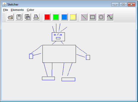
How It Works
The code that enables lines and rectangles to be drawn work in essentially the same way. You can drag the mouse in any direction to create a rectangle or a line. Both types rubber-band as you drag the mouse with button 1 down.
The type of element that is created is determined as a line by default, but you can select Rectangle from the Element menu. When you are creating a rectangle, the constructor sorts out the correct coordinates for the top-left corner. This is necessary because the rectangle is being defined from any of its diagonals, because the rectangle is always displayed from the point where the mouse button was pressed to the current cursor position. The point where the mouse button is pressed can be at any of the four corners of the rectangle. Because the top-left corner always defines the position of a Rectangle2D object, you have to work out where that is.
The getBounds() method in the Element.Rectangle class calls the getBoundingRectangle() method inherited from the base class, Element. You can see why it is necessary to increase the width and height of the bounding rectangle if you temporarily comment out the statements that do this. You see that rectangles are drawn with the right and bottom edges missing.
Defining Circles
The most natural mechanism for drawing a circle is to make the point where the mouse button is pressed the center, and the point where the mouse button is released the end of the radius — that is, on the circumference. You need to do a little calculation to make it work this way.
Figure 19-26 illustrates the drawing mechanism for a circle. Circles are drawn dynamically as the mouse is dragged, with the cursor position being on the circumference of the circle. You have the center of the circle and a point on the circumference available in the methods that handle the mouse events, but the Ellipse2D class that you use to define a circle expects it to be defined by the coordinates of the point on the top-right corner of the rectangle that encloses the circle plus its height and width. This means you have to calculate the position, height, and width of the rectangle from the center and radius of the circle.
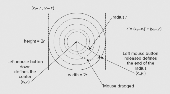
Pythagoras’ theorem provides the formula that you might use to calculate the radius of the circle from the point at the center and any point on the circumference, and this is shown in Figure 19-26. The formula may look a little complicated, but Java makes this easy. Remember the distance() method defined in Point2D class? That does exactly what is shown here, so you are able to use that to obtain the radius directly from the two defining points. When you have the radius, you can then calculate the coordinates of the top-left point by subtracting the radius value from the coordinates of the center. The height and width of the enclosing rectangle for the circle are just twice the radius.
TRY IT OUT: Adding Circles
Here’s how this is applied in the definition of the Element.Circle class:
import java.awt.*;
import java.io.Serializable;
import static Constants.SketcherConstants.*;
import java.awt.geom.*;

public abstract class Element implements Serializable{
  // Code defining the base class...
  // Nested class defining a line...
  // Nested class defining a rectangle...
  // Nested class defining a circle
  public static class Circle extends Element {
    public Circle(Point center, Point circum, Color color) {
      super(color);

      // Radius is distance from center to circumference
      double radius = center.distance(circum);
      position = new Point(center.x - (int)radius, center.y - (int)radius);
      circle = new Ellipse2D.Double(origin.x, origin.y, 2.*radius, 2.*radius);
      bounds = new java.awt.Rectangle(position.x, position.y,
                                  1 + (int)circle.width, 1+(int)circle.height);
    }

    // Display the circle
    public  void draw(Graphics2D g2D) {
      g2D.setPaint(color);                          // Set the circle color
      g2D.translate(position.x, position.y);        // Move context origin
      g2D.draw(circle);                             // Draw the circle
      g2D.translate(-position.x, -position.y);      // Move context origin back
    }

    // Recreate this circle
    public void modify(Point center, Point circum) {
      double radius = center.distance(circum);
      circle.width = circle.height = 2*radius;
      position.x = center.x - (int)radius;
      position.y = center.y - (int)radius;
      bounds = new java.awt.Rectangle(position.x, position.y,
                                  1 + (int)circle.width, 1+(int)circle.height);
    }

    private Ellipse2D.Double circle;
    private final static long serialVersionUID = 1001L;
  }
  // Abstract methods & fields in Element class...
}
Directory "Sketcher 5 drawing sketch circle elements"
You can’t use the base class constructor that requires two arguments because you have to calculate the position for a circle first. A base class constructor call must appear as the first statement in the body of the derived class constructor. Add the following constructor to the Element class:
  protected Element(Color color) {
    this.color = color;
  }
Directory "Sketcher 5 drawing sketch circle elements"
This just initializes the color member.
If you amend the createElement() method in the MouseHandler class by uncommenting the line that creates Element.Circle objects and recompile the Sketcher program, you are ready to draw circles. You are now equipped to produce artwork of the astonishing sophistication shown in Figure 19-27.

How It Works
The circle is generated by the button down point defining the center and the cursor position while dragging as a point on the circumference. A circle is a special case of an ellipse, and a shape that is an ellipse is defined by the top-left corner and the width and height of the rectangle that encloses it. The distance() method that is defined in the Point2D class calculates the radius, and this value is used to calculate the coordinates of the top-left corner of the enclosing rectangle, which is stored in position. The width and height of the rectangle enclosing the circle are just twice the radius value, so the circle is stored as an Ellipse2D.Double object at origin with a width and height as twice the radius.
Because of the way a circle is drawn, the modify() method has to recalculate the position coordinates as well as the width and height. The other methods in the Element.Circle class are much the same as you have seen previously.
Drawing Curves
Curves are a bit trickier to deal with than the other shapes. You want to be able to create a freehand curve by dragging the mouse, so that as the cursor moves the curve extends. This needs to be reflected in how you define the Element.Curve class. Let’s first consider how the process of drawing a curve is going to work and define the Element.Curve class based on that.
The QuadCurve2D and CubicCurve2D classes are not very convenient or easy to use here. These are applicable when you have curves that you define by a series of points together with control points that define tangents to the curve. A curve in Sketcher is going to be entered freehand, and the data that you get is a series of points that are relatively close together, but you don’t know ahead of time how many there are going to be; as long as the mouse is being dragged you collect more points. You won’t have any control points either. This gives us a hint as to an approach you could adopt for creating a curve that keeps it as simple as possible. Figure 19-28 illustrates the approach you could take.

Successive points that define the freehand curve are quite close together, so you could create a visual representation of the curve by joining the points to form a series of connected line segments. Because the lengths of the line segments are short, it should look like a reasonable curve.
Implementing this looks like a job for a GeneralPath object. A GeneralPath object can handle any number of segments, and you can add to it. You can construct an initial path as soon as you have two points — which is when you process the first MOUSE_DRAGGED event. You can extend the curve by calling the modify() method to add another segment to the path using the point that you get for each of the subsequent MOUSE_DRAGGED events.
TRY IT OUT: The Element.Curve Class
The approach described in the previous section means that the outline of the Curve class is going to be the following:
import java.awt.*;
import java.io.Serializable;
import static Constants.SketcherConstants.*;

public abstract class Element implements Serializable {
  // Code defining the base class...
  // Nested class defining a line...
  // Nested class defining a rectangle...
  // Nested class defining a circle...
  // Nested class defining a curve
  public static class Curve extends Element {
    public Curve(Point start, Point next, Color color) {
      super(start, color);
      curve = new GeneralPath();
      curve.moveTo(origin.x, origin.y);       // Set current position as origin
      curve.lineTo(next.x - position.x, next.y - position.y);  // Add segment
      bounds = new java.awt.Rectangle(
                   Math.min(start.x ,next.x),    Math.min(start.y, next.y),
                   Math.abs(next.x - start.x)+1, Math.abs(next.y - start.y)+1);
    }

    // Add another segment
    public void modify(Point start, Point next) {
      curve.lineTo(next.x - position.x, next.y - position.y);  // Add segment
      bounds.add(new java.awt.Rectangle(next.x,next.y, 1, 1)); // Extend bounds
    }

    // Display the curve
    public  void draw(Graphics2D g2D) {
     g2D.setPaint(color);                           // Set the curve color
     g2D.translate(position.x, position.y);         // Move context origin
     g2D.draw(curve);                               // Draw the curve
     g2D.translate(-position.x, -position.y);       // Move context origin back
    }

    private GeneralPath curve;
    private final static long serialVersionUID = 1001L;
  }
  // Abstract methods & fields in Element class...
}
Directory "Sketcher 6 drawing sketch curve elements"
The Curve class constructor creates a GeneralPath object and adds a single line segment to it by moving the current point for the path to start by calling moveTo() and then calling the lineTo() method for the GeneralPath object with next as the argument. You compute an initial bounding rectangle here that encloses the first two points. As always, the height and width of the rectangle are increased by one to ensure all points are enclosed.
Additional curve segments are added by the modify() method. This calls lineTo() for the GeneralPath member of the class with the new point, next, as the argument. This adds a line from the end of the last segment that was added to the new point. The bounding rectangle is extended, if necessary, by adding a 1× 1 rectangle at next to bounds. Adding a 1× 1 rectangle, rather than just the next point, is necessary to ensure that the new point lies within bounds and not on its boundary.
Of course, you need to uncomment the line creating an Element.Curve object in the createElement() method in the MouseHandler inner class to SketcherFrame. Then you’re ready to roll again. If you recompile Sketcher you are able to give freehand curves a whirl and produce elegant sketches such as that in Figure 19-29.

How It Works
Drawing curves works in essentially the same way as drawing the other elements. The use of XOR mode is superfluous with drawing a curve because you only extend it, but it would be quite a bit of work to treat it as a special case. This would be justified only if drawing curves were too slow and produced excessive flicker.
You might be wondering if you can change from XOR mode back to the normal mode of drawing in a graphics context. Certainly you can: Just call the setPaintMode() method for the graphics context object to get back to the normal drawing mode.
Figure 19-29 is mainly curves. In the next chapter you add a facility for adding text to a sketch. Don’t draw too many masterpieces yet. You won’t be able to preserve them for the nation and posterity by saving them in a file until Chapter 21.
As a last flourish in this chapter, you can make the cursor change to a crosshair cursor in the content pane of the window. All that is necessary to do this is to implement the mouseEntered() and mouseExited() methods in the MouseHandler inner class to the SketcherView class:
    @Override
    public void mouseEntered(MouseEvent e) {
      setCursor(Cursor.getPredefinedCursor(Cursor.CROSSHAIR_CURSOR));
    }

    @Override
    public void mouseExited(MouseEvent e) {
      setCursor(Cursor.getDefaultCursor());
    }
Directory "Sketcher 7 with a crosshair cursor"
The mouseEntered() method is called each time the mouse cursor enters the area occupied by a component, the view in this case. You set the cursor to the crosshair cursor by calling setCursor() for the view object. The argument is the Cursor object returned by the static getPredefinedCursor() method in the Cursor class. For the mouseExited() method that is called when the mouse cursor leaves a component, you set the cursor back to the default cursor. With these changes, you should have a crosshair cursor available when you are drawing shapes.
In this chapter you learned how to draw on components and how you can use mouse listeners to implement a drawing interface. You saw how you can derive your own class from the Component class and add it to the content pane for a window to allow text and geometric shapes to be displayed.
The easy way to deal with mouse events is to derive your own class from an adapter class. When you do that, you should use the @Override annotation for each method that you implement to make sure that your method matches the signature of a method in the adapter class.
EXERCISES
You can download the source code for the examples in the book and the solutions to the following exercises from www.wrox.com.
1. Add code to the Sketcher program to support drawing an ellipse.
2. Modify the Sketcher program to include a button for switching fill mode on and off.
3. Extend the classes defining rectangles, circles, and ellipses to support filled shapes.
4. Extend the curve class to support filled shapes.
5. (Harder — for curve enthusiasts!) Implement an applet to display a curve as multiple CubicCurve2D objects from points on the curve entered by clicking the mouse. The applet should have two buttons — one to clear the window and allow points on the curve to be entered and the other to display the curve. Devise your own scheme for default control points.
6. (Also harder!) Modify the previous example to ensure that the curve is continuous — this implies that the control points on either side of an interior point, and the interior point itself, should be on a straight line. Allow control points to be dragged with the mouse, but still maintain the continuity of the curve.
7. Modify Sketcher so that the mouse cursor changes to a hand cursor when it is over any of the toolbar buttons.
• WHAT YOU LEARNED IN THIS CHAPTER
| TOPIC | CONCEPT |
| Device Context | A Graphics2D object represents the drawing surface of a component when the component is displayed on a device such as a display or printer. This is called a device context. |
| Drawing on a Component | You draw on a component by calling methods provided by its Graphics2D object. |
| Implementing paint() | You normally draw on a component by implementing its paint() method. The paint() method is passed a Graphics2D object that is the graphics context for the component but as type Graphics. You must cast the Graphics object to type Graphics2D to be able to access the Graphics2D class methods. The paint() method is called whenever the component needs to be redrawn, |
| Drawing Coordinate Systems | The user coordinate system for drawing on a component has the origin in the top-left corner of the component by default, with the positive x-axis from left to right, and the positive y-axis from top to bottom. This is automatically mapped to the device coordinate system, which is in the same orientation. |
| Obtaining a Graphics Context | You can’t create a Graphics2D object. If you want to draw on a component outside of the paint() method, you can obtain a Graphics2D object for the component by calling its getGraphics() method. |
| Drawing Modes | There is more than one drawing mode that you can use. The default mode is paint mode, where drawing overwrites the background pixels with pixels of the current color. Another mode is XOR mode, where the current color is combined with the background color. This is typically used to alternate between the current color and a color passed to the setXORMode() method. |
| Defining Geometric Shapes | The java.awt.geom package defines classes that represent 2D shapes. |
| Drawing Geometric Shapes | The Graphics2D class defines methods for drawing outline shapes as well as filled shapes. |
| Drawing Using the Mouse | You can create mechanisms for drawing on a component using the mouse by implementing methods that handle mouse events. |
