6
Understanding Optics
Introduction
Optics as a science and a technology covers a tremendous range of material. Fortunately, only a limited subset of this material is essential to the field of laser safety. With a few exceptions, this chapter concentrates on the narrower field of geometrical optics, which is the branch of optics that deals with lenses, mirrors, and optical instruments that use lenses and mirrors. After a brief discussion of the nature of light and the relation of geometrical optics to the more comprehensive fields of physical optics and quantum optics, the fundamentals of the behavior of rays within the geometrical optics formalism are presented. Next, how the behavior of rays can be used to make lenses that focus light and produce images is addressed. The eye is one optical system that is important for laser safety personnel to understand, and it is discussed next. Finally, some optical devices that are commonly encountered in laser research and development laboratories are described.
Nature Of Light
To set the stage for the following treatment of geometrical optics, it is helpful to provide an outline of the more comprehensive modern understanding of the nature of light. Concepts such as the relation between wavelength and color are frequently referred to in geometrical optics but are best introduced as part of the wave theory. Furthermore, in some situations, such as the behavior of very-high-quality optical systems or the propagation of laser beams, the geometrical theory is not completely adequate, and some concepts from the wave theory are required. Finally, some of the common optical components that are discussed in the final section can only be understood by referring to the quantum theory of light.
Because vision is so central to our perception of the world, it is not surprising that people since the beginning of recorded history have tried to understand the nature of light and vision. The concept of a line of sight and the observation of shadows have from ancient times suggested that light is something that travels in straight lines. We can introduce the somewhat abstract concept of a ray of light based on this as shown in Figure 6.1. A ray is a single geometric line of light that originates at some light source, like a point on the candle in the figure, and proceeds until it is stopped at some object. The candle emits rays of light in all directions and from each part of the flame. The rays can be different colors. Some rays from the candle are yellow; others are blue or orange. In this view of the nature of light, the reason we can see the candle is that some of the rays from the candle travel to our eyes. This seemingly simple concept that we perceive visual objects only when rays of light enter our eyes can be very helpful in understanding optical phenomena.
This concept of light as some form of energy traveling in straight lines originating at a source explains many observations regarding the behavior of light, but early in the eighteenth century scientists began to discover cases in which the behavior of light was more complicated. In the phenomenon called interference, when two light rays strike the same point the amount of light energy at the point can be more or less than the total energy in the two rays. Another phenomenon called diffraction is observed in which light energy from a source can reach locations where no straight-line path from the source exists.
Figure 6.1
The light emitted by a candle can be thought of as a collection of rays that travel outward from each point on the flame in straight lines in all directions.

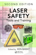
Figure 6.2
Water waves bend (diffract) around an obstacle. The distance between successive peaks is the wavelength.
These effects were explained by the wave theory of light. In this view, light is a wave similar to water waves or sound waves, which are familiar to everyone. The process of interference occurs with waves because when two waves come together they can add up to a larger wave if the crests and troughs of the waves occur in the same location or cancel each other if the crest of one wave coincides with the trough of the other. Diffraction of waves is also readily observed in water waves. If a barrier such as a rock is placed in the path of a wave, the wave can spread around it, as shown in Figure 6.2. As we all know, sound waves commonly go around barriers, so we do not need a straight line of sight from a speaker to our ear to hear a person speaking. An important parameter of a wave is the distance from one wave crest to another, called the wavelength.
Another important parameter is the frequency of the wave. Imagine a cork floating on top of the water. As waves go past it, the cork bobs up and down. The rate at which the cork goes up and down is the frequency. For example, if the cork completes two up-and-down cycles in 1 second, the frequency would be 2 inverse seconds. The unit of an inverse second is also called a hertz. There is a very close connection between wavelength and frequency for any wave. If the wavelength increases, the frequency decreases. In fact, the product of wavelength and frequency is always equal to the speed of the wave.
Of course, light is not a water wave. Rather, it is an electromagnetic wave as are radio and television waves and x-rays. Because other familiar waves travel in some medium (e.g., water waves in water or sound waves in air), scientists initially believed that there must be some medium through which light waves travel. Eventually, however, it was shown that light can travel in a medium consisting of only free space.
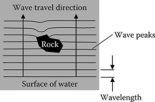
The wave theory of light clarified several other mysteries about the nature of light. First, the color of light was found to depend on the wavelength, the distance from one wave crest to the next. The wavelength of light is very small. The shortest wavelength of visible light is about 0.0004 mm or 400 nm. This corresponds to deep purple light. The longest wavelength is about 0.0007 mm or 700 nm. This long wavelength is a deep red. Each wavelength corresponds to a single primary (rainbow) color, as seen in Figure 6.3. Any color that is not a primary color consists of a mixture of waves with various wavelengths. Figure 6.3 only shows the range of visible light. Although the human eye is not sensitive to wavelengths outside this range, electromagnetic waves with shorter or longer wavelengths do exist. Fundamentally, electromagnetic waves of any wavelength behave just like light in the visible range. When the wavelength is not too far outside the visible range, the technology for generating, propagating, and detecting the radiation is very similar to the technology used in the visible range. Therefore, radiations with wavelengths a little shorter than visible (ultraviolet) or a little longer (infrared) are sometimes referred to as light somewhat loosely. Many lasers emit wavelengths outside the visible range, and this has important consequences in laser safety. The hazard is more severe because it cannot be seen. As with all waves, as the wavelength increases the frequency decreases. The frequency for light at 400 nm is about 750 terahertz (TH; tera = million million, i.e., 1012), and the frequency for light at 700 nm is about 430 TH.
Figure 6.3
Each wavelength of light in the visible range from 400 to 700 nm is perceived as a single primary color. All other colors are combinations of multiple wavelengths.
Radio waves are also electromagnetic waves with a much longer wavelength than visible light. Gamma rays are electromagnetic waves with a much shorter wavelength. These types of radiations propagate through free space just like visible light; but they interact with matter in very different ways, and their associated technologies are very different.
In all these electromagnetic waves, the things that are going up and down in analogy to the surface of water in a water wave are really abstract objects, the electric field and the magnetic field. These are both forces. The electric field is usually the more important. It is oriented to push an electrically charged particle in a direction perpendicular to the direction that the wave is traveling. This is analogous to a cork bobbing up and down in a water wave. The motion of the cork is perpendicular to the direction of travel of the wave. The electromagnetic wave in three-dimensional space can exert a force in any direction that is perpendicular to the direction of travel. If the direction is always the same throughout the wave, it is called linear polarization. Circular and elliptical polarizations are also possible. Any polarization can be described in terms of two special linear polarizations. Often, these two special polarizations correspond to the electric field as horizontal or vertical.
The wave theory can be used to determine the speed at which light travels. In free space, it travels about 300 million m/s. Light can travel through other media as well, for example, water or glass. When it goes through other media, it travels at a slower rate.
Wave theory at first glance seems so different from the geometrical ray point of view that it may seem impossible that both theories are describing the same phenomenon. However, some similarities can be seen by thinking again about water waves. A wave in the open ocean travels in a straight line. The wave peaks are perpendicular to the direction in which the wave travels. So, we could talk about rays for water waves as the direction of travel. A wave encountering a large island, for example, does not bend around it so there is a shadow of the island. It is only when there are multiple waves that can interfere or smaller objects for which the bending of waves is observed that describing waves in terms of rays breaks down. This is exactly the situation encountered in the wave theory of light. All of geometrical optics can be derived from the wave theory as an approximation that is perfectly adequate in many situations. In this chapter, with a few exceptions, we need only this approximation.
The wave theory of light has been very successful in predicting the behavior of light with high accuracy. Nevertheless, there is still more to the story of light. Near the beginning of the twentieth century, a number of observations of the interaction of light with atoms and electrons were inconsistent with the wave theory. This led to the quantum theory of light. In this theory, light is composed of tiny particles of energy called photons. Although it might seem that photons and waves are completely different concepts, the quantum theory shows that they are very closely related. Just like the ray theory can be shown to be an approximation of the wave theory, the wave theory itself is an approximation of the quantum theory. The quantum theory of light is beyond the scope or needs of this book. A few concepts from this theory are discussed in the final section of this chapter, regarding typical optical devices in laser laboratories.
Scattering, Absorption, Reflection, And Refraction Of Rays
With this background of how scientists today understand light, let us return to the ray picture, which is also called geometrical optics, and study the behavior of rays after they leave the source that generates them. Other than simply traveling in a straight line forever, there are only a few other fates that can befall a ray within the geometrical optics model. The principle of conservation of energy dictates that all of the energy carried by a ray must be accounted for by one of the processes discussed next.
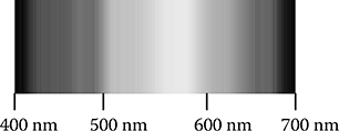
Consider again the candle discussed when the concept of rays was introduced. If the candle is in a dark room, we notice that when it is lit other objects in the room become visible. This is due to a phenomenon known as scattering, which is illustrated in Figure 6.4. One of the rays from the candle strikes the picture on the wall. The ray from the candle stops, but it causes new rays to be emitted from the point where it struck the picture. Rays traveling in all directions are generated. If some of these new rays travel to our eyes, we can see the picture by the light of the candle.
Certain parts of the scattering object are more efficient at scattering blue light, and other parts are more efficient at scattering green. If the illumination contains many colors, then the areas that scatter the most blue light will appear blue. However, the scattering object does not change the color of the rays. That is why in a room illuminated by a red light, everything looks red.
For rays of colors that are not strongly scattered by the object, some of the rays simply cease to exist. They are absorbed by the object. How much is absorbed and how much is scattered depend on the nature of the object and on the color of the ray.
Because energy is conserved, the energy that disappears from the light rays must turn into energy in some other form. In this case, it turns into heat in the illuminated object. With ordinary room lights this heat may not even be perceptible, although with bright floodlights the heating due to absorbed light may be very noticeable. If the light source is a powerful laser, the absorbed energy can generate enough heat to melt or burn the object. The scattering from a surface discussed in this section is sometimes called diffuse reflection.
Figure 6.4
Light originating at the candle can scatter from objects. This scattered light can then be detected by the eye. This is the scientific explanation of how we see something by the light of the candle. A scattered ray has the same wavelength as the ray that induced the scattering.
Notice that the scattered light from the picture is in many ways similar to the light originally coming from a source like the candle that actually generates light. In particular, light rays emerge from the picture in all directions with various colors and energies. When some reach our eyes, we can see the picture just as we see the candle. So, for many purposes we can consider the picture to be a light source just like the candle even though it is only scattering light rather than generating it. We refer to either of these as an object, a word used frequently in geometrical optics to refer to something that provides the rays that propagate through an optical system.
In addition to the picture in the room, suppose there is a smooth shiny surface, say, a mirror. In this case, another phenomenon in addition to scattering and absorption can be observed. We see in the mirror what appears to be a second candle. This is due to the process of reflection. When a ray strikes the mirror, the ray stops, but a new ray is generated. In scattering rays are generated in all directions, but in reflection each ray generates only a single new ray. The new ray has the same color as the original ray but goes in a direction determined by the law of reflection as illustrated in Figure 6.5. First, draw a line perpendicular to the mirror surface at the point where the ray strikes the mirror. This is called the surface normal. The reflected ray leaves the mirror at the same angle from the surface normal that the incident ray comes in but on the opposite side of the normal.
How does this law of reflection lead to the appearance of an image? This is illustrated in Figure 6.6. In this figure, light rays are generated by something called a point source. Like the light rays, a point source is an idealized, abstract concept, but it is used so frequently in geometrical optics that it is important to understand. A point source is a single point from which light rays emerge in all directions. It can be thought of as a single point on the candle, the picture, or some other object. It is used because it can illustrate the concept of imaging much more easily than trying to explain the behavior of all the rays from a more realistic object.
Figure 6.5
The law of reflection states that the angle of reflection equals the angle of incidence.

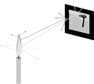
Figure 6.6
By applying the law of reflection to all the rays from the point source, which strike the mirror, it can be seen that an image of the point source appears behind the mirror.
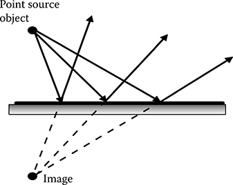
The rays from the point source that do not strike the mirror behave just as discussed. They might travel in a straight line forever, or they might strike some other object and scatter or be absorbed. The rays of interest here are the ones that strike the mirror; a few are illustrated in Figure 6.6. Each of these rays obeys the law of reflection. So the ones that strike the surface at a small angle generate a reflected ray at a small angle, and the ones that strike the surface at a larger angle generate reflected rays at larger angles. The reflected rays begin at the surface of the mirror. However, if these rays were to be continued backward, as shown by the dotted lines in the figure, they would intersect in a single point that is directly behind the mirror from the point source at the same distance behind as the point source is in front. This point is called the image point.
How does this explain what we see when we look at a mirror? Remember that what we see depends only on the light that gets into our eyes. If we are looking at the mirror, the rays entering our eyes are exactly the same as if there is no mirror but instead there is a point source at the location of the image. For interpreting the meaning of the light falling on our eyes, our brain takes no account of the fact that these rays do not originate behind the mirror. Thus, we see the image.
To complete the description of imaging by a mirror, note that for some extended sources such as the candle the rays from every point on the object behave just like those from the one point source discussed. Each forms an image directly behind the mirror surface. Therefore, when looking into the mirror the rays reaching the eye are just the same as that would reach the eye if a candle were located behind the mirror. The brain interprets the rays as a candle behind the mirror.
The fourth process that a ray can undergo, refraction, is a little more complex. It occurs when a ray traveling in one medium enters a different medium. As mentioned, a light ray travels at a slower speed when it is traveling in a transparent medium other than free space. The speed that it travels with depends on what the medium is and the wavelength of the ray. In water, the speed of a green ray is about 225 million m/s. The speed is determined by a property of the medium called the refractive index, usually symbolized by the letter n. The larger the refractive index, the slower the light travels in the medium. The refractive index of free space is 1. All other materials have a larger refractive index. Although the index of refraction of air, as of any material, is larger than 1, it is so close to 1 (1.0003) that in most cases the difference is ignored.
Figure 6.7
When a ray goes from one medium to another with a different refractive index, the ray’s direction changes. If, as shown here, the second medium has a larger refractive index, the ray bends toward the surface normal.
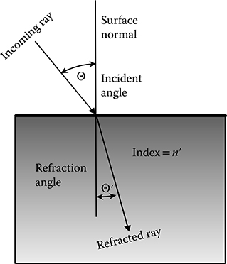
When a ray traveling in one medium encounters a new medium, in addition to changing its speed it also changes direction, as shown in Figure 6.7. In this figure, a light ray is traveling in a medium with an index of refraction n and crosses a plane interface where it begins to travel in a medium with a different index of refraction, n’. As in reflection, the change in direction is mathematically characterized by a change in the angle the ray makes with the surface normal. The change in direction follows a law of refraction similar to the law of reflection. If the second medium has a larger refractive index than the first, the angle gets smaller, as shown in the figure. If the second medium has a lower index, the angle gets larger. Also, the larger the incident angle, the more the ray bends. If the incidence angle is zero, normal incidence, the ray does not bend at all, although its speed does slow down. The mathematical form of this law, usually called Snell’s law, is not needed in this presentation. The interested reader can find it in the bibliography. A commonly encountered case is when one of the two media is air, which for most practical purposes has the same refractive index as the vacuum of free space.
Figure 6.8
Rays from an object in a low-index medium refract at the plane interface with a higher index material. An image is formed that appears farther from the interface than the object.
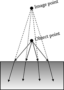
As in the case of reflection, instead of a single ray we consider a point source. Figure 6.8 shows a point source in a low-index medium for which some of the rays travel into a higher index medium. All the rays bend toward the normal to make the refracted angle smaller than the incident angle, but the ones with a higher incidence angle bend more. The result is that to an observer below, in the high-index medium the rays reaching the observer’s eye appear to come from a point farther away than the object point. Again, if the source is an extended source composed of many, many point sources, each forms an image in the same way. The observer will perceive an image of the extended source at a distance farther from him or her than the actual source. Nothing will be perceived as existing at the actual object location because no rays that seem to originate from this location reach the eye.
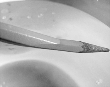
When the object is in the high-index medium, the opposite happens. That is, the image appears closer than the object. This can be seen in the photograph shown in Figure 6.9. The tip of the pencil is in water, and the camera is above in air. By following the outline of the part of the pencil above water, you can see that the apparent position of the pencil tip is closer to the surface of the water than the actual tip. The rays from the parts of the pencil that are under water refract when they leave the water. Since these rays are the only way in which the camera, or an eye, can detect the pencil, it appears as if the pencil is located where the refracted rays diverge. If you put your finger in the water and try to touch the tip of the pencil where it appears to be, you will find that it is not there at all. It is, of course, located where you would expect it by continuing the lines of the pencil part that is not in water.
Figure 6.9
When the object is in a higher index material as the tip of the pencil is in this figure, the image appears to be closer than the object.
I have discussed all the processes that can occur to light rays but so far only mentioned scattering and absorption on surfaces. These two processes can occur in bulk, meaning that they occur within the medium that the light travels. Before concluding this section on the behavior of light rays, I discuss these subjects.
When a light ray travels through a medium other than free space, its energy may decrease as it travels. This can be caused either by bulk scattering or by bulk absorption. In bulk scattering, new light rays going in all directions are generated at each point of the ray’s path through the medium. A simple experiment can illustrate bulk scattering. If you shine a flashlight or a laser pointer into pure water, the beam is difficult to see. Pure water does not scatter light very well. If a small amount of powdered milk is dissolved in the water, the beam becomes easily visible. It is important to understand that the light that enters your eye allowing you to see the beam is from the scattered light and not from the beam directly. If you shine the same flashlight through the air, which has negligible scattering, again you do not see the beam. Bulk absorption differs from bulk scattering in that the energy from the ray decreases without generating any new rays. According to the law of conservation of energy, this lost energy must turn into energy in another form. The lost energy in ordinary absorption turns into heat in the medium, which then increases the temperature. Figure 6.10 shows how an incoming ray can undergo all these processes in a material. Usually, all the light rays that are generated have the same wavelength as the incident ray. This is called the regime of linear optics. In nonlinear optics, discussed separately, new wavelengths can be generated.
One special reflection mechanism should be mentioned as it is important for both optical devices and laser safety. This is the phenomenon of Fresnel reflection, named after the French scientist who studied it in the eighteenth century. If light is incident on an interface between two materials with different refractive indexes, some of the light is reflected and some is transmitted. The amount reflected depends on the two refractive indexes, angle of incidence, and direction of the electric field (polarization). This Fresnel reflection is why you see a reflection in a pane of glass. For ordinary glass, in the visible range of wavelengths at normal incidence the amount reflected is about 4%. This is important in laser safety because Fresnel reflection often leads to stray beams. Sometimes, it is important to reduce Fresnel reflection. This is done using a thin antireflection coating on the interface surface.
Figure 6.10
By conservation of energy, all the energy of an incident light ray must be reflected, transmitted (refracted), scattered, or absorbed. The process of absorption converts the light into heat. The other processes change the incident ray into other light rays traveling in different directions.

Again, I stray from the geometrical view of light to discuss a topic that is becoming important in many situations in laser safety. The topic of saturated absorption requires knowledge of the quantum theory of light to fully explain, but a qualitative sketch can be given here. Usually, absorption is just a property of the material and the wavelength of the ray. On an atomic scale, what is happening is that atoms (or molecules in some cases, but I just say atoms to avoid repeatedly saying atoms and molecules) in certain states can transition to states with higher energies when exposed to light with the right wavelength. Next, an atom or molecule can convert that absorbed energy into heat. Only once has it done that can it absorb more energy. Conversion of the absorbed energy into heat can happen very quickly. However, some lasers today emit very short pulses, as short as a few femtoseconds (one-billionth of a millionth of a second). These pulses, although short, can be extremely intense during the time that they are on. It can then happen that during the time that the pulse is on the intensity is so high that all the available atoms make the transition to the higher energy state and the pulse is so short that they do not have time to convert that energy into heat. No atoms will be available to absorb any more of the energy in the pulse. If this occurs, then any additional energy in the pulse will not be absorbed at all. The absorption is said to be saturated. The amount of energy absorbed by saturated absorption may be several orders of magnitude less than that which would be absorbed normally.
Why is this important for laser safety? Most laser-protective eyewear uses absorption to reduce the amount of laser light to which the eye could potentially be exposed. If an ultrashort pulse laser is used, the absorption in the laser eyewear could become saturated. The degree of protection afforded by the eyewear may then be insufficient to mitigate the hazard. When specifying laser eyewear for use with short-pulse lasers, it is necessary to ensure that the eyewear has been tested to verify its suitability at the pulse length used.
Lenses And Optical Imaging
In the preceding section, the laws of reflection and refraction were introduced to show how they operate at a plane interface. Both these laws work exactly the same for curved surfaces, with one important difference. For both reflection and refraction at a plane interface, the surface normal was used to define both the incident ray and the reflected or refracted ray. The surface normal is different at each position on a curved surface. For curved surfaces, the surface normals used in the laws of reflection and refraction must be those at the position where the ray strikes the surface.
To illustrate how refraction works at a curved surface, the operation of a simple plano-convex lens is described. The object in the center of Figure 6.11 is the lens. It is a piece of glass with one surface ground into the shape of a sphere and the other surface flat. This is an example of a positive lens. Negative lenses are introduced later.
The rays entering the lens are all parallel to the symmetry axis of the lens. This is called a plane wave. Recall that in wave optics the wave peaks are perpendicular to the rays, so the wave peaks here form planes that are perpendicular to the rays. The waves in Figure 6.2 are plane waves before bending around the rock. Another way to think about this is as rays coming from a point source at a large distance to the left of the lens. The rays from the point source fan out in all directions, but the only rays that reach a distant location must be the ones that are traveling in the right direction to reach that location. A familiar example of a point source at a large distance is starlight. The plane wave is important in laser safety because, in many cases, a laser beam can be considered to be a plane wave.
Even though the rays are traveling in the same direction, they strike the first surface at different incidence angles because that surface is curved. The ray in the center enters the lens at normal incidence, and therefore it does not bend at all. The rays farther from the center enter at larger angles the farther they are from the center and therefore bend more. At the flat surface of the lens, the rays bend again when they go from the glass back into air. As a result of these two refractions, the rays that come from the point source traveling in the same direction converge after passing through the lens. In fact, they converge in just such a way that they intersect at a single point called the focal point of the lens. The distance from the lens to the focal point is called the focal length of the lens.
Figure 6.11
Refraction at a curved surface can focus a plane wave to a point.

Consider the ray paths after they pass through the focal point. They fan out from the focal point just as the rays fan out from a point source. They are not traveling in all directions, though, because the lens only collected a limited number of the rays from the source. However, for an observer in the path of those rays the rays are just as if the point source were located at the focal point. Recall that the brain interprets vision based only on the light that enters the eye, so the perception is exactly as if the point source were located at the focal point. Therefore, we call the focal point the image of the point source at infinity (i.e., at a very large distance). The ability to essentially take an object at one location and transform it into an image at another location is very useful and is the basis for many optical instruments, such as telescopes, microscopes, and cameras.
It is at this point that a traditional optics tutorial begins to get quite complex with numerous cases derived from different curvatures, different object locations, and multielement optical systems. The specialized terminology alone can be daunting to the uninitiated. Fortunately for the readers of this chapter, there is not enough space to go into all of this. However, a few more concepts are needed to treat issues arising in the context of laser safety. The first is that of imaging of an extended object rather than a point source and not necessarily at a large distance. Then, I briefly return to the wave nature of light to discuss the role of diffraction in imaging. Finally, I mention negative lenses and virtual images.
In Figure 6.12, the same lens discussed for Figure 6.11 is shown. The object is an extended object. The object can be anything; for example, it could be the candle discussed in the preceding section. For purposes of illustration, the object is just represented as an arrow. The object is not at a large distance from the lens. The effect of the lens on the rays is found by considering each point on the object as a point source. A full picture of what happens can be obtained by considering only two of these points.
First, consider the rays from the base of the arrow. Just as in the case of the distant point source, all the rays come together after passing through the lens to form an image of the base of the arrow. The image, however, is not at the focal point but at a point farther from the lens than the focal point. This is because the rays incident on the lens are not parallel but diverging. The lens bends the rays by just about the same amount as in the previous case; but because they start out diverging, this amount of bending does not give them as much convergence as previously, so they intersect farther from the lens.
Figure 6.12
Imaging of an extended object at a finite distance from a lens can be understood by tracing rays from two points on the object.

Now, consider the rays from the tip of the arrow shown in the diagram. The symmetry axis of the lens is called the optical axis. Therefore, the tip of the arrow is called an off-axis object point. After passing through the lens, these rays also converge, but they converge to an off-axis image point in the same plane as the base of the arrow. The rays from intermediate points on the object also converge to the corresponding points in the image. Imagine that there is a screen located at the plane of the image. A screen is a material that does a good job of scattering light of all colors equally. A person looking at the screen will have light scattered into his or her eye from each location where rays from the object strike the screen. The only light coming from the screen will be from where the light that passed through the lens strikes it. This pattern of light will be in the shape of the object, so an image of the object will appear on the screen. Any image that can be projected onto a screen like this is called a real image. Notice that the image is upside down, or inverted, from the original object.
The image can be larger or smaller than the object. The ratio of the size of the image to the size of the object is the magnification of the optical system. As the object is brought closer to the lens, the magnification becomes larger and the image moves farther away from the lens. When the object is exactly one focal length in front of the lens, the image moves to an infinite distance.
Sometimes, the wave theory of light cannot be ignored when discussing imaging. In fact, the effect of diffraction has important consequences for laser safety. So far, it has been stated that all the rays from a point source converge to a single point. This suggests that a point source would have an image on a screen that is just a point. It turns out that, due to the wave nature of light, the image of a point source is not quite a point but is smeared out into a diffraction spot. The size of this spot increases if the diameter of the lens gets smaller, if the focal length gets larger, or if the wavelength gets larger. There is also the case that the lens may not perfectly converge the rays to a spot. In this case, we say the lens has aberrations. In some cases, the aberrations cause more smearing than the diffraction, in which case the diffraction can usually be ignored. On the other hand, if there are aberrations but they cause much less smearing than diffraction, the aberrations can be ignored and the lens is referred to as diffraction limited.
Figure 6.13
A negative lens forms a virtual focus.

Another type of lens and another type of image are illustrated in Figure 6.13. Notice that one surface of the lens is concave. The object is again a point source at a large distance from the left edge of the page. The first surface that the rays encounter is flat, and all the rays strike it at normal incidence. Therefore, the rays do not bend. At the second surface, the rays strike at different angles. Because they are going from a higher index to a lower index, their angle of refraction is greater than their angle of incidence. The result is that rays farther from the lens’ center diverge more and, to an observer of the light passing through the lens, they appear to come from a point on the other side of the lens. This point from which the rays diverge is called the focal point of the lens. Because the focal point is on the opposite side of the lens compared to the positive lens, this is called a negative lens.
Notice that the rays never actually pass through the focal point; they only appear to come from it. Therefore, this image of the point source cannot be projected onto a screen. For this reason, this type of image is called a virtual image. Virtual images can also occur with positive lenses when the object is closer than the focal length. A magnifying glass is a positive lens used in this way. When looking through a magnifying glass, you are seeing a virtual image of the object that is larger than the object.
Mirrors with curved surfaces are also common in laser technology. Just as with lenses, because the rays from a plane wave strike various points on a curved mirror at different incidence angles, the rays can be brought to a focus for a concave mirror or diverge from a virtual focus for a convex mirror.
Complex optical systems such as camera lenses or the setups in laser research laboratories consist of combinations of the lenses and mirrors discussed. When more than one optical element is used, the system is analyzed by considering each element in turn in the order that light strikes it. The image produced by the first element, whether it is real or virtual, becomes the object for the second element, and so on until the last element produces the final image.
Eye
Once the basics of imaging are understood, a wide array of optical instruments can be demonstrated: the telescope, the microscope, the camera, and so on. Details of the construction and operation of these optical instruments can be found in the bibliography at the end of this chapter. For purposes of laser safety, the most important optical instrument is the human eye; therefore, this one instrument is discussed here.
A highly simplified model of the eye is shown in Figure 6.14. The eye is a nearly round globe about 1 in. in diameter. Most of the eyeball is filled with a fluid called the vitreous humor, which has an index of refraction close to that of water. There is in addition a lens, which has material with various indices somewhat higher than that of water. The outermost part of the eye is the cornea. The cornea is the interface between the air and the fluid inside the eye. It is one of the few places on the body where living cells are exposed to the environment. There is also an iris, which controls how much light enters the eye. At the back of the eye is an area called the retina, which consists of light-sensitive cells that convert light to electrical impulses that are transmitted to various parts of the brain via the optic nerve. There are many other features of the eye: muscles, aspheric surfaces, structures to reduce light scattering, different types of light-sensitive cells, and other fluids. The ones pointed out here are all that are required to understand the functioning of the eye.
Figure 6.14
The eye is a very complex optical instrument. The drawing shows only a basic summary of the important parts of the eye.
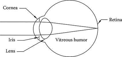
Light arriving at the eye from a distant point source is shown in Figure 6.14. The rays are bent due to several curved surfaces at which there is a change in index of refraction. This is a multielement lens. Most of the bending is done at the cornea, but the small amount of bending at the lens is also very important. In the figure, the distant source is imaged on the retina. If the source were closer, we have learned that the image would move farther away from the lens and would not fall on the retina. However, muscles in the eye are able to bend the lens and change its curvatures. This has the effect of shortening the focal length and thus moving the image back to the retina.
The lens can only be deformed by a limited amount. If the object is brought in so close that the lens cannot be deformed enough to bring the image back to the retina, then the object cannot be clearly imaged. The closest location that an object can be placed and still be clearly imaged is called the near point. In young people, this is approximately 25 cm. As the eye ages, the lens becomes less flexible and the near point moves farther away. Reading glasses are positive lenses that make up for the reduction in focusing power.
The light-sensitive cells on the retina are remarkably sensitive. However, if the amount of light reaching them is too small, they will not be activated. The amount of light can be increased by increasing the size of the pupil, which is the opening in the iris. On the other hand, in a very brightly lit room there may be too much light. Then, the pupil will get smaller to reduce the amount of light entering the eye.
The figure indicates that the distant point forms a point image on the retina, but as mentioned, due to the wave nature of light, the image is not a point but a diffraction spot. The eye is very close to a diffraction-limited optical system.
The complicated operation of the eye, including the change in the lens’ shape, opening and closing of the iris, and processing of the information sent to the brain, is mostly controlled by the unconscious mind. This highly sophisticated optical system can function for as much as a century. It is very remarkable.
Eye And Laser Safety
The laser today is ubiquitous. There is one in every CD and DVD drive. They are used in communications, in store checkout counters, as laser pointers in presentations, and in land surveying. In all of these applications in which the general public makes use of lasers, lasers are either configured in such a way that they are not hazardous or completely enclosed within an inaccessible beam. In industrial and research and development applications, however, this is not always the case. High-power and even relatively low-power lasers can potentially cause severe, irreversible eye damage.
There are a number of different mechanisms by which lasers can cause damage to the eye. The most common one can be understood simply by looking again at Figure 6.14. Suppose that the plane wave incident on the eye is not from a distant point source but from a laser emitting a visible wavelength (400–700 nm). The eye will focus the light onto the retina just as if the laser beam is starlight, but the amount of optical energy involved is many orders of magnitude larger. As with the point source, this energy is absorbed by the light-sensitive cells. However, as discussed, absorption changes the light energy into heat energy. If the heat generated causes temperature to rise too much, the light-sensitive cells will be destroyed. The area over which the temperature rises can be larger than the spot itself due to heat conduction. If this occurs on the part of the retina associated with peripheral vision and if the laser is not too powerful, this could cause a blind spot in the field of vision. However, if it occurs in the small region of the retina that is used for detailed viewing, the result could be partial or complete blindness. With short laser pulses, the damage may be caused not by heat but by ablation, in which parts of the cells are essentially exploded. In the blue and green regions of the spectrum, laser light can also break chemical bonds in the cells and cause damage even if there is not enough increase in temperature to destroy the cells.
The light-sensitive cells in the retina are not sensitive to light with a wavelength longer than about 700 nm. However, the lens, the vitreous humor, and other parts of the eye are still transparent to rays with wavelengths as long as 1400 nm. This means that lasers with wavelengths in this range can cause the same injuries described. This presents a very dangerous situation because the light from these lasers cannot be seen. In the visible range, the hazard due to laser eye exposure is mitigated to some extent by the natural aversion response (blink), which limits the amount of time that the light illuminates the retina. Of course, there is no such aversion response with invisible light. The wavelength range from 400 to 1400 nm is called the retinal hazard zone.
For wavelengths longer than 1400 nm, little energy is transmitted to the retina. The radiation is absorbed in the lens or other parts of the eye depending on the wavelength. Although the absorbed energy will still cause heating, the temperature rise will be smaller because the energy is absorbed over a large volume rather than in a small spot on the retina. Also, the delicate light-sensitive cells are not heated. The spectral range with wavelengths greater than 1400 nm is sometimes called the eye-safe region. It is only eye safe in the sense that the maximum permissible exposures (MPEs) in this region are orders of magnitude higher than those in the retinal hazard zone. There are certainly lasers with wavelengths in this range that can cause serious eye injury.
For lasers with wavelengths shorter than 400 nm (ultraviolet), a similar situation occurs. Again, the eye is not transparent to the radiations. However, there are two important differences between the far-infrared and the ultraviolet wavelengths. First, the eye absorbs most of the radiation very close to the front of the cornea. Second, unless the laser intensity is very high any damage to the cornea is due to chemical changes such as those caused by sunburn. This is the same injury that can happen when viewing nonlaser ultraviolet sources. This injury, called welder’s flash, is very painful but usually causes no permanent injury because the cells on the cornea naturally replace themselves quickly. Of course, this exposure can also increase the risk of cancer. For these reasons, the ultraviolet region of the spectrum is not considered eye safe even though there is no retinal hazard. In fact, for certain wavelengths and exposure durations the MPE for ultraviolet can be lower than the MPE in the retinal hazard region of the infrared range.
Figure 6.15
Diffusely scattered laser light is less hazardous than direct exposure to a laser beam because only a small fraction of the light enters the eye. Under some circumstances, the spot size on the retina can also be larger, which further reduces the hazard.
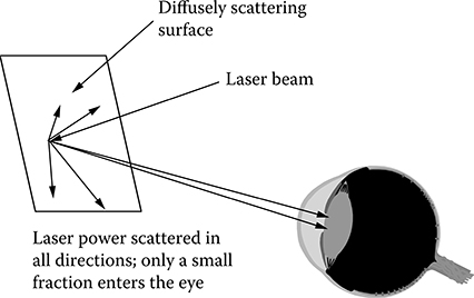
Next the difference between direct laser exposure and exposure to diffusely scattered laser light is discussed. Figure 6.15 shows a laser beam impinging on a diffusely scattering surface. As discussed, all the laser energy is carried off by the scattered rays (unless there is some absorption also). Therefore, most of the radiation is harmlessly directed away from the eye. Only a few rays get into the eye. For this reason, diffusely scattered light is much less hazardous than direct laser light. In fact, except for class 4 lasers diffusely scattered laser light is not a hazard. Notice that the farther the eye from the diffuse reflection, the fewer the rays that enter the eye. Therefore, the diffuse hazard decreases with distance in contrast to the hazard of direct laser exposure, which is nearly independent of distance.
There is another way that diffusely scattered light may be less hazardous than direct laser light in some cases, but not always. Sometimes, the laser spot is large enough that when it is imaged by the eye onto the retina the image is large enough to spread out the heat deposited on the retina. This reduces the rise in temperature. This is the reason for the correction factor CE in American National Standards Institute (ANSI) Z136.1.
Optics In A Laser Research Laboratory
An industrial laser safety officer (LSO) may encounter lasers in a wide variety of settings. The evaluation of all the hazards may be very simple or very complex. In some modern laser research laboratories, the task may be daunting just due to the variety of components and systems that may be encountered. This section presents a sampling of the types of equipment that may be present in a laser laboratory along with some comments about the associated laser safety issues. The list is not necessarily exhaustive.
Lasers and Laser Amplifiers
The laser is a device that is difficult to explain without good knowledge of the quantum theory. Fortunately, the principles of laser operation are not very important for laser safety considerations. The central part of a laser oscillator is some sort of a gain medium, with a crystalline or glass rod, tube of ionized gas, jet of dye, and p–n semiconductor junction being the most common. The gain medium is excited by an energy source called a pump. The pump may be an electrical current, a flash lamp, or even another laser. After being excited by the pump, the gain medium emits light, which is recirculated through the gain medium by a resonator until it reaches the desired energy, after which it leaves the resonator through either an output coupler or an electro-optical switch. This then is the output laser beam.
Most lasers emit a narrow beam of light. High-power lasers may emit a beam that is not narrow. Commercial solid-state lasers generally have a beam diameter less than a centimeter, but custom-built, high-power lasers in research facilities may have dimensions of tens of centimeters. Some laser diodes and laser diode arrays emit light that has such a large divergence that it is not really a beam. Many lasers emit rays with exactly one wavelength; others emit several wavelengths, sometimes simultaneously. Still others can be tuned to emit at any desired wavelength within a range.
There are, of course, a great variety of lasers. Commercial lasers exist with wavelengths from 157 nm to 12 million nm. Powers of commercial lasers can be as high as 30 kW. Pulse lengths can be as short as 10 femtoseconds. Custom-built lasers can stretch the parameter range even further.
This large variety of specifications means that the LSO must carefully read the specifications of any potentially hazardous laser. For example, if a laser is capable of emitting several different wavelengths, is the selected wavelength the only wavelength that will be emitted? If even a small amount of another wavelength leaks out, it may be sufficient to pose a hazard. For tunable lasers, does the laser eyewear cover the entire tuning range of the laser?
Some laser systems include laser amplifiers to increase the energy in the beam. The amplifiers may be embedded in a commercial laser along with the oscillator or may be mounted outside the oscillator. A laser amplifier is similar to an oscillator in that it consists of a gain medium and a pump, but usually there is no resonator; the light generated by the oscillator (or a previous amplifier stage) is passed through the gain medium. In some cases, the beam is sent through an amplifier several times. Many times, the beam size is increased as it is sent from one amplifier stage to the next.
Laser Beam Transport Optics
Mirrors and lenses are used to convey a laser beam from where it is generated to where it will do something useful. Flat mirrors are the most commonly used elements in laser systems. They are nearly always made reflective using a thin-film, multilayer dielectric coating. Dielectric coatings use interference of light to enhance the reflectivity of a surface. They can be tailored to provide nearly any desired reflection characteristic, such as very high reflectivity at the laser wavelength. Unlike silvered mirrors, though, the reflectivity at wavelengths other than the laser wavelength may be small. For a laser operating in the infrared or ultraviolet range, the reflectivity throughout the visible range may be small. To someone unfamiliar with these mirrors, it can be hard to realize that what appears to be just a transparent piece of glass actually reflects 99.9% of the laser light.
Also unlike silvered mirrors, the portion of the laser beam that is not reflected from the mirror is not absorbed; rather, it is transmitted. If, as is sometimes the case, the back of the mirror is polished, the leakage beam will be transmitted out through the back of the mirror. This is one of the many sources of stray beams in laser laboratories. Even if this is only 0.1% of the energy of the original beam, it can easily be a hazardous beam. As the coating ages or as the humidity in the room changes, the amount of transmitted light can increase. If the reflectivity falls to 99%, the loss in the reflected beam might not even be noticed, but the stray beam transmission would increase by an order of magnitude to 1%. Also, the amount of light transmitted can dramatically increase if the coating is scratched or otherwise damaged. For these reasons, it is best practice to locate an opaque beam block behind the mirror and never to count on the reflectivity of the mirror for protection against laser hazards.
One particular hazard of mirrors is that they can create upwardly directed beams. Most of the time, laser beams are directed parallel to the surface of an optical table that is kept below eye level. However, occasionally it is necessary to change the level of the beam. This is done with a pair of mirrors in a periscope configuration in which one mirror directs the beam up and the other then directs it again parallel to the table but at a higher level. If the system becomes misaligned so that the beam misses the upper mirror, the beam travels upward until it encounters something that stops it. In several unfortunate incidents, the upward-traveling beam was stopped by a worker’s eye. Extra caution is required whenever upward-directed beams or beams at or near eye level are employed.
Lenses are also used to transport laser beams. One might think that a laser beam propagates a long distance without changing, but diffraction can greatly change the profile of a laser beam. A beam that is created to have a very uniform intensity over its cross section can develop hot spots after propagating some distance. This is undesirable if a flat intensity is needed for the application and if the hot spots are intense enough to cause damage to some of the optical elements in the system. A telescope consisting of two (or occasionally more) lenses can project an image of the flat-intensity beam to another location. The telescope can also be used to change the size of the beam, perhaps to increase the beam size for a following amplifier stage. In most telescopes, the laser beam is brought to a small focal spot between the two lenses. With high-power lasers, the intensity in this small spot can be large enough to cause air to ionize, creating something like a small ball of lightning. When the beam passes through this ionized air, the beam is distorted. For this reason, the beam transport telescopes for high-power lasers are enclosed in a vacuum tube. These long, skinny tubes with lenses as vacuum seals and a vacuum hose coming out of them are ubiquitous in laser research laboratories.
Lenses also frequently have their surfaces coated with a thin-film dielectric coating. The purpose of this coating is to reduce reflectivity. The glass that is the lens material will reflect several percent of the laser beam. This may not seem like very much, but a complex laser system can have dozens of lenses, and laser light can be very expensive. The dielectric coating can reduce the reflectivity to a small fraction of a percent.
Even if dielectric coatings reduce reflectivity, there is still some reflection from each surface of the lens. These reflections from the lens are usually called ghosts, and they are another source of stray beams in a laser laboratory. They can be more problematic than those from mirrors for a number of reasons. There are more of them. In addition to one from each surface, there can be secondary ghosts in which the light reflected from one surface reflects again after hitting another surface. Often, these reflections cannot be blocked because they are in the beam path. Because the reflections can be from curved surfaces or may pass through curved surfaces, they can be divergent or convergent. The convergent beams, in addition to being an eye safety concern, can cause damage to the laser if they cause a small focus to form on the laser optics. Like the focus in the beam transport telescope, they can sometimes cause air to ionize. The divergent beams (and the convergent beams after passing through focus) can become large and difficult to block. As they get larger, of course, they become less hazardous, but determining the nominal hazard zone of these beams can be very difficult. Often, prudence requires that they all be considered hazardous. This is a major reason why laser eyewear should always be required in a laser laboratory even if the workers are sure that they cannot be exposed to the main beam.
Setting up or realigning a laser beam transport system can be one of the most hazardous operations involving lasers. When first locating a mirror or lens on a table, the laser beam may initially stray far away from the path it is supposed to take. Low-power alignment lasers should be used as much as possible. Part of setting up a laser laboratory should always be locating all the stray beams and blocking them if possible. In a complex system with lasers outside the visible range, this can be a difficult task. The stray beams may take some unexpected paths. Sometimes, building an opaque enclosure around the laser system may be the best way to control these hazards.
Laser beam transport systems frequently include beam splitters. Beam splitters can be of several types. The simplest is a mirror that reflects only a portion of the light and allows the rest to be transmitted. In some cases, such as for interferometry or holography, the transmitted and reflected beams have about the same intensity. In other cases, the majority of the beam is reflected and a small portion is transmitted, often for use in a diagnostic measurement device. Alternatively, the transmitted beam may be the small-intensity beam used for diagnostics, whereas the reflected beam contains the majority of the energy. Uncoated beam splitters fall into this last category. These use Fresnel reflection to generate the reflected beam. This has several advantages. It does not require any coating of the surface, the amount reflected can be very accurately predicted, and the uncoated surface can be much more resistant to laser damage than a coated surface.
Other types of beam splitters are used as well. A dichroic beam splitter transmits some wavelengths and reflects others. This is useful in frequency conversion, discussed separately, since there usually is some unconverted light that must be removed. Finally, polarizing beam splitters transmit one linear polarization and reflect the other.
Nonlinear Optical Devices
All the events that were previously said to be the potential fate of a ray involved either the generation of new rays with the same wavelength or the disappearance of the ray. In the quantum theory of light, it is possible to generate new rays with different wavelengths. Components that do this are frequency conversion devices. Another device that works on the same principle can increase the energy of a beam at one wavelength at the expense of a beam at another wavelength. This is called optical parametric amplification. Components that always produce rays of the same wavelength as the incident beam belong to the realm of linear optics. The devices in this section are called nonlinear optics.
One very common example of the first process is a harmonic generator. It consists of a special crystal that a laser beam is directed through in a certain direction. Part of the laser beam is converted to a wavelength exactly half of the original wavelength. In other words, a laser beam with a wavelength of 1000 nm would be converted to a wavelength of 500 nm. It is possible but less common to generate other harmonics, such as one-third or one-fourth of the original wavelength, in a single crystal. Instead, these harmonics are generated using the closely related process of sum-frequency generation. To obtain the third harmonic (wavelength one-third of the original), a frequency doubler first converts some of the light to half the wavelength. Next, the unconverted light and the second harmonic are combined in another crystal to produce the third harmonic.
Usually in harmonic generation, the harmonic beam travels along the same path as the original beam. Even if the harmonic generation is very efficient, there will be some residual unconverted light. Unless the residual is removed completely, the hazards of both wavelengths need to be taken into account for safety considerations. This is why it was mentioned that for lasers emitting multiple wavelengths the possibility of more than just the desired wavelength being present must be considered. Lasers emitting multiple wavelengths usually have harmonic generators inside them.
Another nonlinear optical device is the optical parametric amplifier. It is also based on a crystal illuminated by two laser beams of different wavelengths. Of the two, the longer wavelength is called the pump and the shorter is called the signal. In this process, some of the energy of the pump is extracted and goes into producing more energy in the signal beam. In the process, a third beam is also produced, called the idler. Because the energy taken from the pump goes into both the signal and the idler, the signal can at most be increased by half the energy in the pump. Sometimes the idler beam itself is desired, in which case this same process is another frequency conversion process called difference frequency generation.
There are many other nonlinear optical processes as well, with Raman scattering and Brillouin scattering being two of the more common ones. In Raman scattering, light is scattered from atoms and molecules. I have discussed scattering of light from atoms and molecules, but in that case the scattered light had the same wavelength as the incoming ray and the atoms were left in the same state as before the scattering. If the atoms change to another energy state during a scattering, the wavelength of the scattered light changes. In Brillouin scattering, light scatters from a sound wave. The change in wavelength in Brillouin scattering is very small. Brillouin scattering is the basis for a device sometimes found in high-power laser laboratories called a phase conjugator. A phase conjugator acts like a mirror with a very unusual law of reflection. The reflected ray retraces the path of the incident ray. If there are any aberrations on the beam, the phase-conjugated reflection has exactly the opposite aberration. When the reflected beam retraces its path through the system that produced the aberrations, the aberrations on the beam are cancelled, resulting in a high-quality beam with no aberrations.
Whenever nonlinear optical devices are used, it is important to ensure that all potential wavelengths are included in the safety analysis. Most nonlinear devices must be carefully aligned to work properly. Therefore, the energies of the various wavelengths to be used for safety calculations must always be the worst-case numbers to allow for misalignments or damage to the nonlinear devices.
Diagnostics
Much of the optical and nonoptical equipment in a laser research laboratory consists of devices to measure and record characteristics of lasers or of the experiments for which lasers are used. Some typical measurement equipment includes power and energy meters, photodiodes for pulse width measurements, cameras, interferometers, and spectrometers.
To diagnose the laser beam itself, a sample of the beam must be obtained. There are two ways of doing this. A mirror in the beam transport system can be given a coating that is not highly reflective but has a transmission of a few percent. Then, the beam transmitted through the mirror can be used for diagnostics. Alternately, a diagnostic beam splitter can be used. This is a piece of glass with two flat surfaces that reflects a portion of the beam for diagnostics. The reflectivity of an uncoated piece of glass is 3% to 4%, depending on the type of glass and the wavelength. A dielectric coating can be used to increase or decrease this value, depending on the need. Of course, both surfaces of the beam splitter reflect light. Often, the beam splitter will be wedged (the two surfaces are not exactly parallel to each other) so that the two reflections can be separated. Both of the beams may separately be used for different diagnostics. If only one of the reflections is used, the second becomes another stray beam that must be blocked.
Good diagnostics can be an important aspect of laser hazard management. If the important parameters of a laser can be monitored with remote diagnostics and displayed on oscilloscopes, monitors, or other display devices and, if needed, adjustments can also be performed remotely, the need to access the laser beam can be minimized. Occasionally, diagnostics can also introduce optical hazards. The absorbing surfaces of energy meters are often smooth and can generate specular reflections, which can be hazardous. Similar to many laboratory hazards, this one tends to cause problems primarily during the initial alignment procedure.
Conclusions
Some of the most basic principles of optics have been discussed in this chapter. By mastering these basics, a better appreciation of the functions of various devices and setups likely to be found in laser research and development laboratories can be obtained. It is important for an LSO to know the right questions to ask to get a realistic assessment of all the optical hazards in a laboratory. Some of these can be very subtle and may not be appreciated by the workers in the laboratory. Being knowledgeable about the equipment in a laboratory and its common uses also enhances the LSO’s appreciation of the work that is being done in the laboratory. Solutions to laser safety issues that are developed with an understanding of the scientific purposes for which the equipment is used are more likely to not hamper the work in the laboratory while still mitigating hazards.
Of course, the discussion here only involved the basics of this vast field. To learn more, there are several references given to some of the standard books on several aspects of geometrical and wave optics and to laser technology.
BIBLIOGRAPHY
Fowles, Grant R., Introduction to Modern Optics, Second Edition, 1989. Dover: New York.
Hecht, Eugene., Optics, Fourth Edition, 2001. Addison-Wesley: New York.
Jenkins, Francis A. and White, Harvey E., Fundamentals of Optics, Fourth Edition, 1976. McGraw-Hill: New York.
Johnson, B.K., Optics and Optical Instruments, 1960. Dover: New York.