
19
Power and Energy Meters
From Sensors to Displays
Calibrating Devices
This approach was good for tweaking lasers for maximum output, but then calibration became an issue. How could one calibrate these devices to read the correct power? This is still a valid topic today as applications require higher degrees of accuracy and precision.
The National Institute of Standards (NIST) in Boulder, Colorado and Gaithersburg, Maryland have developed gold standards that quantify the uncertainty of products that are used to measure laser power and energy. Manufacturers send their equipment to NIST to have them measure uncertainty values at various wavelengths where they have developed primary standards based on physical constants. In the case of Boulder, they use a water calorimeter and measure the temperature rise of water, a known constant. This calorimeter approach is used to determine the uncertainty of a measured value of laser power at very specific power and/or energy levels.
These products then become the manufacturer’s gold standards, which are used to calibrate silver standards and then working standards. Working standards are used on a daily basis to calibrate production volumes of detector heads that are sold to many users of lasers in a broad array of laser applications.
Some manufacturers, such as Gentec-EO, use gold standards to directly calibrate production sensor heads to increase the accuracy, and decrease the uncertainty of measurements traceable to NIST. NIST-traceable spectrophotometers are used to characterize the reflection across a broad spectrum, that is 300–2500 nm. This information can be stored in the E-Prom of the sensor head and used with a smart instrument that can then apply a factor for wavelengths that are not calibrated individually with a laser source.
As lasers progressed and developed other characteristics, like repetitive pulsing, variable pulse widths, high power, more wavelengths, and so on, pyroelectric sensors were developed to measure the energy output whereas variations of form and factor were created to handle the widening array of lasers being developed for new and exciting applications. Measuring precise laser power and/or energy became an important issue in the world that now included semiconductor manufacturing, uVia drilling, dermatology, and ophthalmic applications such as LASIK vision correction.
In the following sections, we will review the basic sensor types—thermopile, pyroelectric, and silicon photodiode—and cover the instruments that are used to display the power and/or energy of the lasers. We will explore what parameters one must look at to determine the best detector head for a particular laser and then match it up with a readout. This chapter will give some historical perspective on the evolution of power and energy meters and what the future holds.
Determining Sensor Type
One of the first things you need to do to select the correct sensor head is look at the laser parameter. Determine whether the laser is continuous wave (CW) or pulsed. If the laser is CW, then just finding out the minimum and maxim power that is expected tells you whether you will need to use a photodiode- or thermopile-type sensor head to measure it. Of course, the wavelength of the laser may be the first consideration as photodiodes have a limited wavelength range. Thermopile sensor heads have a very broad wavelength response.
If your laser is pulsed, then you may want to consider a pyroelectric sensor to measure pulse-to-pulse energy in joules. In addition, they typically allow you to convert joules to average power in watts and measure the pulse repetition frequency when used with a display instrument that supports such functionality.
If you are just measuring the output of the laser to tweak it up or adjust optics, a thermopile (series of thermocouples) power meter works just fine. They are less expensive than pyroelectric energy sensors and meters, and their associated processing electronics are much simpler than pyros. If you want to know the stability of the laser on a pulse-to-pulse basis, a pyroelectric or silicon sensor head allows you to measure every pulse up to 250 kHz pulse repetition frequency.
Let us take a closer look at the details of thermopile sensors, pyroelectric sensors, and photodiodes.
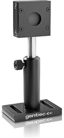
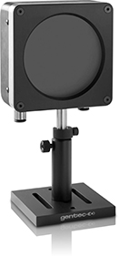
Thermopiles
Thermopile theory and parameters:
Generate voltage when there is a temperature difference at junction between two dissimilar metals, an array of thermocouples.
A thermopile is an array of thermocouples.
Broadband spectral response: deep ultraviolet (DUV) to far-infrared (IR).
Dynamic range is from 50 μW to 25 kW.
Used to measure average laser power, such as for CW and repetitively pulsed sources.
Can be used in single-pulse mode in which a single pulse of energy is measured. There is a time delay between pulses of ~3–5 seconds whereas the algorithm and electronics integrate the pulse and the sensor head cools sufficiently between pulses.
Diameters of the sensing area range from 10 to 210 mm.
There are two basic types of thermopiles:
Axial flow
Heat flows along the axis; these have long time constants, from tens of seconds to minutes.

Radial flow
Heat flows from the center to the edges, shorter time constants (in seconds) unless probe has very large area.
With radial flow thermopiles DC voltage is generated when heat flows from hot to cold junctions between two dissimilar metals.
Most companies today use thermopiles that are radial flow (primarily because of their faster speed of response).
Disks are made of aluminum for powers to 300 W and copper for kilowatts sensor heads.

There are two basic types of absorbers:
Surface absorbers
The laser light is absorbed in the front surface of the sensor.
Optical black paint: 500 W/cm2, 50 mJ/cm2 at 10 nanoseconds
High-temperature ceramic: up to 45 kW/cm2, 600 mJ/cm2 at 10 nanoseconds
Typically used for CW lasers and some pulsed lasers
Volume absorbers
The laser light is absorbed in a bulk material and then conducted to the metal disk. Typical lasers include Q-switched relative high energy Nd:YAG, Ruby, Alexandrite, and Erbium lasers with energy >100 mJ.
Colored glass: good for high peak power, 10 J/cm2 at 1064 nm, but low average power threshold at 50 W/cm2.
Combination of glass/ceramic: good for high peak power and moderate average power.
All volume absorbers are typically used for high-energy short pulse width lasers.
Diffusers: They will diffuse and scatter the light before reaching absorbing surface.
Thermopile sensors heads are cooled in one of three ways:
Air cooled
Water cooled
Fan cooled
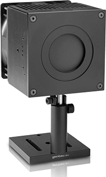
Generally, air-cooled sensors have a larger physical size and have fins to use convection to get rid of the heat. If one needs a smaller physical size, then either a sensor with a built-in fan or a sensor with water channels to get rid of the heat would be considered.
When choosing a particular model of thermopile sensor, one needs to consider various laser parameters and match one up that meets those parameters:
Maximum power
Minimum power
Beam spot size
Does one need a surface absorber or volume absorber?
Are there any size constraints?
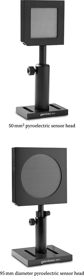
Pyroelectrics
Pyroelectric sensors are suitable for measuring pulse-to-pulse energy from nearly any type of pulsed laser. They are spectrally broadband, from x-ray to millimeters, so measuring lasers from DUV (i.e., 157 nm) to far-IR (i.e., 10.6 μm) to THz is not a problem. They can measure single pulses and repetitive pulses to hundreds of kilohertz.
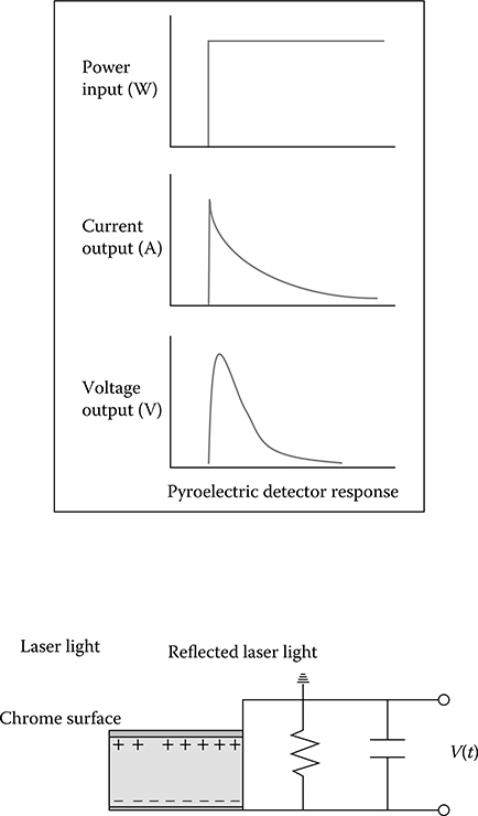
Pyroelectric theory and parameters:
Respond to the rate of change of temperature, the source must be pulsed, chopped, or modulated.
When designed as a joulemeter sensor, they essentially act like capacitors in that they integrate pulses and produce an AC signal whose peak voltage is proportional to the energy in the pulse.
Very fast, up to 250 kHz per pulse, possible at 1 MHz and beyond in the future.
Broadband DUV to far-IR.
Dynamic range from sub microjoules to joules.
A sensor made from a pyroelectric material is an AC thermal detector.
Ideal for measuring chopped or pulsed light sources (lasers).
The current output from the sensor is proportional to the rate of change of temperature.
Broadest band sensor known, x-ray to millimeters.
All must be surface absorbers, as any type of volume absorber would add heat dissipation time making them virtually useless as fast temporal sensors.
Four decades of range from a single detector.
1–100 mm diameter active areas.
Silicon Photodiodes
A silicon photodiode is a solid-state device that converts incident light into an electric current. It consists of a shallow diffused p–n junction.
A photodiode sensor produces a current proportional to light intensity and has a high degree of linearity over a large range of light power levels—from fractions of a nanowatt to about 2 mW. Above that light level, corresponding to a current of about 1 mA, the electron density in the photodiode becomes too great and its efficiency is reduced causing saturation and a lower reading. Some manufacturers have sensors with a built-in filter that reduces the light level on the detector and allows measurement up to 30 mW without saturation. In addition, another removable filter allows measurement to 300 mW or all the way up to 3 W.
Photodiode theory and parameters:
Spectral range from 190 to 1100 nm for silicon.
Dynamic range from sub nanowatts to milliwatts, 3 W with filters.
A response time of 50 milliseconds for power and average power measurements.
Can measure CW power, and average power of repetitive pulses.
Can be designed to measure energy per pulse up to 250 kHz (with Gentec-EO Mach6).
Diameters of sensors are typically 5–10 mm.
Displays
When power meters were first developed, they were typically used with just one type of sensor. There was one type of display that you could plug into one type of sensor: pyroelectric, thermopile, or photodiode. This was well before the advent of microprocessors and E-PROMs. One had to use dials and screws to adjust the gain and correction factors for each head.
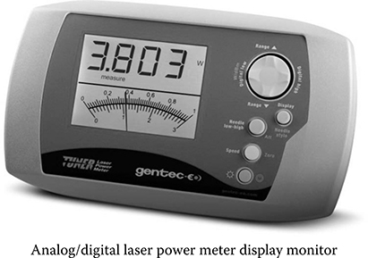
Initially most displays were analog meters, which worked for tweaking or tuning lasers. To read the actual laser power, one then had to look at the ticks on the analog dial to take the reading. As readouts evolved, so did the way they displayed their readings.
With the coming digital and computer electronics transformation, displays got a lot smarter. Almost overnight, displays had small computer chips and heads had E-PROMs. A display could read the contents of the E-PROM of each individual sensor head, know what type it was, and what dynamic range it had so that it would set range limits. One could even program each individual head’s discrete calibration points and obtain a complete spectral curve. This revolutionized the world of power and energy meters. Meters and sensors became plug-and-play. All three sensor types could be used with one display. This not only made life much easier for users of power and energy meters, but also reduced the cost of ownership as one meter could be used with multiple heads.
With LCDs and, later on, dot matrix displays, one could more easily read laser power, although many people still liked to use analog meters for tweaking and tuning because of their fast response and easy trend displays, up or down. Some manufacturers started making instruments with both analog and digital displays, and some simulated an analog meter movement with a dot matrix display (see photo of analog/digital monitor).
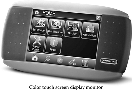
Riding on the coattails of the display technology evolution, with the proliferation of color screen devices like PDAs, GPSs, and cell phones, the power and energy meter manufacturers can now afford to put color screens on their displays producing vivid vibrant displays that can be altered for color depending on the type of laser used and the glasses needed. For this technology the future has arrived. Some are now like dedicated mini touch screen hand-held tablets (see photo of Maestro).
As part of the computer revolution, the ability to record data became easier. With older analog displays, some had analog outputs that could be connected to an analog recorder that then plotted on paper a record of the meter’s recordings. Then along came direct computer connectivity. The first was a serial interface, RS-232, and then a parallel interface, IEEE-488 (GPIB). Computer programs were created to collect and analyze the data on a computer.
Some instruments, such as Gentec-EO’s Maestro, have a built-in USB flash drive that record as much data as the flash drive can hold, in addition to RS-232, analog output, and the first of its kind, an Ethernet port.
Today, RS-232 and GPIB seem to be fading. The connector of choice is now USB. Who knows what it evolves to into the future.
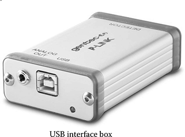
PC Options
Sometimes one just wants to control the sensor and record the output data via a PC. They do not need a meter with an analog needle of digital display. Everything would be handled remotely from the PC. And while you are at it, can you make them more than one channel, and a version that I can connect to Ethernet and therefore read if from nearly everywhere in the world? Well, that is here now, with USB interface boxes like the P-LINK below, that are available in 1, 2, or 4 channels. And the S-Link below has either a USB or a USB and Ethernet connection in 1 or 2 channels.
Into The Future
Recently introduced instruments into the marketplace are built-in USB sensor heads. These completely do away with the meter and even the PC USB interface box. They have the conditioning electronics all imbedded in the sensor head cable that terminates into a standard USB 2 connector. This simplifies everything; no extra box to plug into, that then connects to the PC. Just plug the sensor head cable, which has USB 2 connector on the end, straight into your PC or laptop. The included software then recognizes it and guides us through all the measurement parameters.
Who knows what other developments may occur in the future? I, for one, am looking for the unobtainium and indestructium materials that will be able to stand up to the most powerful lasers ever developed with nary a burn mark or fracture or pit in the absorbing surface. The data will be instantly analyzed and transmitted anywhere in the world in picoseconds and displayed on some kind of four-dimensional interactive display. The possibilities are endless.
Maybe there will be an application that works with Google Glasses, which collect the data wirelessly from the sensor head and allows the user to look to the side, up, or down, for measurement readings while adjustments to the laser are made.