
8
How to Select Optical Mounts
Getting the Most Out of Optical Mounts (Understanding Optical Mounts)
Introduction
When choosing optics, a common mistake among many engineers is overlooking the integration of optical mounts into their system. There are a variety of mounts available for holding lenses, prisms, mirrors, filters, and other common optical components. Some examples include bar-type mounts, gimbal mounts, adjustable kinematic mounts, fixed mounts, and jaw clamp mounts. When cost is a deciding factor, simple fixed mounts will be more than adequate. However, for applications that require fine positioning, adjustable, stable, kinematic mounts are essential to the integrity of a precision optical system.
Optical Mounts Specifics
A three-dimensional rigid body has exactly six degrees of freedom (DOF): X, Y, and Z are translational DOF, and Rx, Ry, and Rz are rotational DOF. A mount is considered kinematic if all six DOF are fully constrained. Most laboratory kinematic optical mounts use the classic cone, groove, and flat constraint system, as illustrated in Figure 8.1, and use two or three adjustment screws. Two adjustment screws, at the groove and the flat, can be used to adjust the rotational DOF. Because the axis of rotation is behind the optic, there will be a slight translation of the optic when an adjustment is made. A third screw can be placed over the cone to compensate for unwanted translation. The three-screw configuration enables the optic to be rotated as needed using the first two adjustments screws and then returned to its original position along the Z-axis with the third.
Figure 8.1
Top plate and adjustment screws of 1-in. kinematic mount.
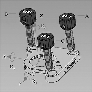
Table 8.1 Contributions of Individual Errors and Root Sum Square (RMS) Total Error
Movement | Beam 1 (µm) | Beam 2 (µm) |
1 | 1 | 1 |
2 | 2.4 | 1.6 |
3 | 0 | 0 |
4 | 0 | 3.6 |
5 | 1 | 1 |
RSS | 2.14 | 4.19 |
RSS, root sum square. |
|
|
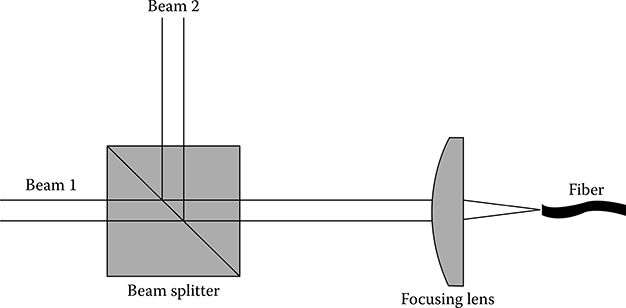
To illustrate the importance of choosing the right optical mounts, consider an application that consists of a 25-mm cube beam splitter and a 12-mm focal length lens to combine and couple two 3-mm beams into a 0.12 numbered aperture fiber. To ensure the highest coupling efficiency, assume that both focused spots need to be centered on the fiber to within ±2 µm.
Each component will contribute to the overall positioning error in the system, which can be calculated by the root sum square (RSS) (see Table 8.1). Because each element potentially has six DOF, there are many combinations of movement that can occur. For simplicity, only the following movements are considered:
Translation along the optical axis of the lens by 1 µm
Rotation of 400 µrad of the focusing lens about a point 4 mm from its nodal point
Translation along the optical axis of the beam splitter by 2 µm
Rotation of 150 µrad of the beam splitter about the optical axis
Translation along the optical axis of the fiber by 1 µm
Clearly, the system in Figure 8.2 undergoes too much movement for beam 2 to maintain the ±2 µm required for high coupling efficiency. Factors that may contribute to misalignment are mount resolution and instability from thermal effects, vibration, and gravity (often referred to as pointing stability).
Resolution of kinematic mounts is typically classified into two categories: linear resolution and angular resolution. The thread pitch of the adjustment screws determines the linear resolution, whereas the placement and thread pitch of the adjustment screws provide the angular resolution; 80–100 TPI (turns per inch) adjustment screws are the industry standard. Although higher resolution can be obtained by simply using adjustment screws with a larger TPI count, this is not always optimal because finer threads are easily damaged.
Sensitivity is another parameter, often provided by manufacturers, that is related to resolution. Because most kinematic mounts are manually driven, it is helpful to know the minimum obtainable movement of the optic. In general, fingertips are sensitive enough to resolve a 1° turn of the screw. The movement of the optic that corresponds to a 1° turn is what is used to define sensitivity.
Thermal stability indicates how well the mount will perform when subjected to changes in temperature. For minimum deflection from thermal effects, the mount’s coefficient of thermal expansion should be matched to that of the optic. Certain types of stainless steel match up very well to glass and are the preferred choice when thermal stability is of utmost importance. Although aluminum has a higher thermal expansion coefficient, kinematic mounts made from it still perform well in typical laboratory environments.
In addition to movement from thermal conditions, the effects of gravity over time will contribute to the overall misalignment error. Pointing stability is the measure of this error, specified as an angular movement, and is defined at a certain temperature, time lapse, and applied load.
Figure 8.2
Fiber coupling system.
Vibration can also degrade optical system performance. Misalignment from low-level vibration will lead to blur in the image plane. Attempting to image with a high-power microscope objective without using a vibration isolation platform will result in this phenomenon. Materials with higher stiffness values have greater fundamental or natural frequencies and faster settling times, resulting in less vibration disturbance.
A big drawback of many mounts is having to drop, rather than place, the optic into position. With the steep cost of precision optics, it is highly undesirable to drop them into place even if it is only from a few millimeters. Choosing a mount with finger cuts incorporated into the design allows for guided placement of the optic, which will reduce chances of chipping and fracture.
Conclusion
The key to successfully choosing an optical mount is to prioritize the surrounding requirements. When critical alignment is of primary importance, the user should choose kinematic mounts that offer high resolution and excellent position stability. Thermal stability is increased when all connecting components are constructed from the same material. In the majority of setups, this would consist of stainless steel hardware as most optical benches have stainless steel tops. However, a setup constructed entirely from stainless steel components can prove costly. When cost is more of a concern and alignment is less critical, aluminum is a perfectly suitable alternative.