15
Room Access Interlocks and Access Controls
Introduction
In a perfect world, all persons working with or around laser systems would be aware of, and respect, every hazard. In this perfect world, every laser system would be enclosed for Class 1 operation, and opening the door to a room containing a laser would not jeopardize the safety of personnel in the hallway. In many cases, the laser safety officer (LSO) can work with the researchers to actually create this perfect world. In other cases, the nature of laser research requires a flexibility that enclosed laser systems cannot provide. In either case, the LSO will need to understand the principles of laser interlocks and access controls.
By definition, the LSO is granted the authority to monitor and enforce the control of laser hazards. This can place the LSO in an uncomfortable position. An LSO has the authority to implement the safety controls, but may have little experience in electrical safety engineering. When he or she mentions the word interlock, the laser users will often put up their defenses with thoughts of intrusion, sacrifice, and expense. The intrusion is the feeling that the LSO is placing new demands on the users that they have thus far avoided. The sacrifice is a thought that they must give up flexibility when implementing the safety interlock system and a fear that their experiment will be ruined when the system is tripped. The expense is the monetary cost of the system that takes away from funds that can be used for other research components. These concerns are valid, but not impossible to overcome. It is rare for a newly introduced safety protocol to be greeted with open arms; however, time after time we have observed cases for which the first room interlock installation was fought tooth and nail by the researcher, but after gaining experience with a well-designed system, the other researchers were waiting in line for their own systems to be installed.
Budgeting For Engineered Safety
The safety dollar is a rare coin in many facilities. Given this limited resource, the LSO should make every effort to spend it wisely. At the same time, the LSO should realize that the researcher who complains about not having $3000 to $5000 for enhancing safety will easily spend that same amount on a new laser power meter or a single optics translation stage. It really just boils down to priorities.
If a facility wants to use lasers, it must also budget for their safety. When possible, the funding for safety should be placed in the control of the LSO for dedicated safety expenditures. This funding may indeed be taken off the top of funds that were granted to a researcher, but in doing so, the LSO needs to actually spend this money for the benefit of the researcher. This benefits the LSO, the laser researcher, and the facility. The following case is a typical scenario.
Case 1
The LSO approaches Bob (the researcher) and informs him that the facility is adopting a new safety standard. “Bob, to comply with this standard, you’re going to have to buy laser eyewear, laser safety signs, curtains, and an access control system. I’ll be back in 1 month to check on your progress.”
Obviously, this is creating an adversarial relationship between the LSO and the researcher. Even if worded differently, the message is the same. It is also fostering an unhealthy attitude about safety. Every time the researcher hears about some new safety protocol, the first response will be to think, “How much is this going to cost me?”
Case 2
The same LSO approaches Bob and informs him of the new safety standard. “And here’s what I’m going to do for you. To get this going, I’m going to buy you some new eyewear, safety signs, curtains, and an access control system. I’m going to arrange to have this installed and train your people. If you ever need a new sign or safety label, just call me, and I’ll have one printed for you. If you ever need new prescription safety eyewear, do the same.”
Do you see the difference? This is, of course, an idealized case, but this approach will make the safety pill much easier to swallow. It is important to realize that the largest safety expense is an up-front onetime expense that will likely last for decades, so a safety budget should be padded at the front end to account for this.
Creating The Perfect World, One Laser At A Time
Clearly, whenever possible, it is preferable to create a Class 1 enclosure around a laser system. Once enclosed, the laser can operate day in and day out without a need for external safety protocols, protective eyewear, warnings, and so on. The up-front expense of the enclosure may seem high, but the long-term benefit and risk reduction make it a wise investment.
The availability of modern extruded aluminum construction hardware makes the design and construction of an enclosure quite simple. One name brand product known as 80/20®, produced by 80/20 Incorporated, uses the registered slogan: The Industrial Erector Set. Indeed, this product can be used by the everyday researcher to build an enclosure without the need for cutting, drilling, or welding. The manufacturer provides hardware cut to the length specified, and an enclosure can be assembled with a simple hex screwdriver. Anodized aluminum panels slide effortlessly into the slots of the extruded structure, forming a light-tight enclosure. The construction of an enclosure does not completely alleviate the responsibility of meeting other safety standards. There are labeling and simple panel interlock requirements that must also be fulfilled. These are generally well within the capabilities of the end user. Of course, there will be scenarios for which the power levels of the laser system exceed the burn-through characteristics of the aluminum. There are laser consultants available to help with these cases.
The large rectangular enclosure that completely surrounds an apparatus is not always the best design. As Figure 15.1 shows, a high-power laser-manufacturing apparatus can be created, which provides Class 1 safety but allows a product to move freely through the process while personnel are free to work in the immediate proximity without danger of exposure.
Figure 15.1
An industrial Class 4 laser operating in Class 1 conditions. A, Product delivery and take-up spools; B, enclosed laser and beam delivery tubes; C, a shroud made of a safety filter material that completely blocks diffuse and specular reflections above MPE levels; D, a beam dump immediately beneath product. Beam is safely dumped even if product is removed.

Interlocks
Definition
The term interlock refers to a hardware device that, when activated, will immediately reduce the laser emission below maximum permissible exposure (MPE) levels. This device may be a mechanically or electrically activated shutter, or it may be an electrical trip of the laser system power source. The interlock is often broadly defined as a room interlock system, by which access controls, door or floor sensors, or motion detectors are interconnected to cause a rapid reduction in laser emission below the MPE when activated.
The interlock is not always obvious. For example, a technician removing an interior cover plate of a common DVD player may release a spring-loaded switch that prevents operation of the laser. This is a hardware-engineered safety interlock designed to protect the technician who has reached the dangerous portion of the machine, but it typically goes unnoticed by the average consumer.
Reasons for Interlocks
When dealing with Class 3B and Class 4 lasers, the danger is real, not just a sign on the door. The American National Standards Institute (ANSI) Z136.1 (Section 4.3.9.2, p. 31) definition of the use of the Danger sign reads: “‘DANGER’ indicates an imminently hazardous situation which, if not avoided, will result in death or serious injury. This signal word is to be limited to the most extreme conditions.”
All too often we find the word is overused, leading to a false sense of the meaning and a relaxed attitude. One could even argue that the use of the word is overprescribed within the ANSI standard itself. Clearly, there are differing levels of danger. Something can be dangerous when misused, such as the common laser pointer, or it may be extremely dangerous in its normal operation, such as a high-power laser research experiment. Unfortunately, we have only one danger posting.
Engineered safety interlocks and entryway controls are a method of ensuring that seriously dangerous systems (Class 4) are contained and respected. Proper implementation of the interlocks will limit the laser access to qualified, trained individuals and help prevent harm to those who are not properly trained on the operation and safe use of the laser.
One of the most difficult tasks an LSO will perform is the accurate calculation of the nominal hazard zone (NHZ) for a laser system. To make matters worse, the laser layout in a research or an educational setting can change with every experiment. The release of ANSI Z136.1-2007 has now simplified this task. In lieu of performing the calculations, the LSO can simply declare the entire room as a laser area and provide adequate controls at the perimeter of the room. These controls are most often implemented using interlocks and engineered access controls.
Laser Manufacturing Requirements
The U.S. Food and Drug Administration’s Center for Devices and Radiological Health mandates are released as federal code in Title 21 of the Code of Federal Regulations (21CFR). The subsections of this title list the required elements to which manufacturers must comply if they are offering a product for sale in the United States.
The following is a summary of 21CFR chapters related to laser products:
21CFR1000–1005: Broad-scope list of devices regulates the records and reports that must be produced and retained by a manufacturer and the import/export requirements.
21CFR1010: General performance standards, certifications, and variances.
21CFR1040.10: Performance standards for manufacture of laser products. This is where one will find the information pertaining to the laser housing interlocks, remote electrical interlocks, labeling, and power classification. In addition to providing the required information for manufacturers, this standard is a useful reference for the end user when the user is building a Class 1 enclosure around Class 3B or Class 4 laser systems.
21CFR1040.11: Performance standards for specific-use laser products. Medical, survey, leveling, alignment, and demonstration laser products must meet criteria listed in this chapter as well as all criteria listed in 21CFR1040.10.
These chapters are collectively known by the acronym FLPPS, which stands for Federal Laser Product Performance Standards.
All federal regulations are provided free of charge to the public by the federal government. They can be viewed and printed from the Internet. A searchable database can be found at http://www.accessdata.fda.gov/scripts/cdrh/cfdocs/cfcfr/cfrsearch.cfm.
FLPPS Requirements Specific to the Remote Laser Interlock
Every commercial Class 3b and Class 4 laser sold in the United States shall include a remote electrical interlock connection. The connection will have two terminals that need to be electrically shorted to each other. If the circuit opens, the laser will not emit a laser radiation hazard above the MPE threshold. The manufacturer is given leeway in choosing the method to be used to accomplish this task. The manufacturer may use an electromechanical shutter or electro-optical modulator behind the laser housing, or may choose to electrically shut down the power supply to the laser. The only real constraints are that the device must be fail-safe and the voltage used for this remote interlock circuit shall be less than 130 V. Although it is unlikely that a modern manufacturer would use this voltage, one needs to be aware of the potential shock hazard that may be present at this connector. If you are unsure of the potential on a particular laser, consult the manufacturer. The fail-safe requirement is an important feature. When a safety circuit has tripped the laser off, the laser must remain off until it has been restarted by an operator even if the safety circuit trip was momentary.
Lasers or Laser Systems Manufactured for In-House Use
Every effort should be made to meet the intent of FLPPS when a facility is constructing a laser or laser enclosure for its own use. The FLPPS is intended for the safety of the end user. With the increased availability of high-power laser diodes, any person with a basic understanding of electronics can construct Class 3B or Class 4 lasers without any knowledge of laser physics or laser safety. This places an increased emphasis on the LSO to monitor and enforce laser safety issues.
A facility that fully adopts the ANSI Z136.1 standard is effectively adopting FLPPS. A majority of the FLPPS requirements are repeated (almost verbatim) in Section 4.3 of the ANSI Z136.1 standard. This repeat of the FLPPS requirements within the ANSI standard provides beneficial safety information but can lead to confusion when trying to implement end user–engineered safety controls. ANSI Z136.1-2007 Sections 4.3.1, 4.3.2, 4.3.3, 4.3.4, 4.3.5.1, 4.3.7, 4.3.8, and 4.3.14 are FLPPS specifications that are expected to already exist as a performance feature in a commercially certified product. These items should be verified to exist on receipt of a laser and should be checked periodically to verify their functionality. If the laser or laser system is built in-house, compliance with these ANSI sections is an expectation.
End-User Interlocking Requirements
There is a legal mandate in FLPPS to provide an external interlock on all commercial Class 3B and Class 4 lasers. It is somewhat interesting that there is not a federal legal mandate for the end user actually to use it. In fact, the interlock connector will most likely come from the manufacturer in an electrically shorted state. This is unfortunate because the lasers are often placed into service without consideration of a proper interlock system configuration.
Why is the use of a remote interlock not mandated? There are thousands of possible laser applications. Many applications would not require the connection to an external interlock control system. Instead of mandating the use of an interlock, the ANSI Z136 series of standards provide several methods of instituting an engineered laser safety program.
Engineering Controls
ANSI Z136.1-2007 (Section 4.1, p. 24) states: “Engineering controls (items incorporated into the laser or laser system or designed into the installation by the user) shall be given primary consideration in instituting a control measure program for limiting access to the laser radiation.”
Engineered laser safety concentrates on three specific areas:
Physical protection from the hazard in the form of curtains, enclosures, or barriers
Visual warning of the hazard in the form of signs and electronic warnings
Engineered area or entryway safety controls to control access and trip the interlock if needed
Physical Protection from the Hazard
Physical protection from a laser hazard is the first line of defense for personnel protection. If a laser system can be operated in a closed environment without the possibility of exposure above the MPE, then the system is Class 1 safe. The most common example of this is the DVD-RW drive in a normal computer. Although it contains a Class 3B laser with powers up to several hundred milliwatts, its operation is safe and requires no outwardly noticeable warnings or interlocks. The designers of this device have ensured that there are no conceivable methods for exposure to the hazard. The same approach can be extended to larger laser systems in the laboratory research, medical, and industrial environments. Unfortunately, as the physical size of a system grows, the risk of human exposure becomes more likely. Service access panels require interlocks, windows require attenuation filters, and curtains require damage threshold analysis. Although it is possible to create large Class 1 laser systems, sometimes the only reasonable approach is to designate a laser room as a laser-controlled area.
In this approach, the perimeter of the room becomes the enclosure. All personnel within the room would wear laser-protective eyewear, and personnel outside the room would not be at risk for exposure. Ultimately, the perimeter of the room must still be evaluated for laser safety with regard to the possibility of generating toxic fumes, burning, or even worse, wall penetration. When designating an entire room as a laser area, one must also ensure that the hazard does not extend outside the door if opened. Several methods can be used to control this hazard, including curtains, barriers, or electronic interlocks. If ordinary drywall is acceptable for the perimeter of the room, then a simple drywall labyrinth at the entryway is an option. The materials chosen to perform these functions must be evaluated for flammability and decomposition product toxicity. Material selection for protection also varies widely with laser wavelength. As an example, many people are surprised to find that common glass can be used as a screen attenuator for a CO2 laser hazard up to certain power levels. For high-power systems, the process of selecting a barrier may require expertise beyond the capabilities of the LSO and the local researchers. In this case, laser curtain manufacturers should be able to provide recommendations. For moderate-and low-power Class 4 systems, the barrier selection can be as simple as verifying the breakdown resistance of a given material in a controlled manner with the laser in question. Any tight-weave, nonflammable fabric may suffice for a laser curtain if it has been properly evaluated for damage and permeability.
Although an LSO may choose to designate an entire room as an NHZ, every effort should still be made to mitigate the potential for exposure within the room. Beam tubes, beam blocks, temporary barriers, and attenuators can be used to define the direction and power of a beam hazard. As mentioned, the 80/20 extruded aluminum product (or similar products) can be very useful in this regard.
Visual Warnings
The visual warning is the second line of defense for protecting personnel from a laser hazard. The ANSI standard provides clear instructions describing the text and logos to be used on signage for laser areas (Section 4.7) The design of the sign can follow the ANSI Z535 standard or the International Electrotechnical Commission (IEC) 60825-1 standard. There are companies that sell these signs, but there are also several sites on the Internet that provide free of charge image downloads for printing your own.
Laser areas designated Class 3B should, and areas designated Class 4 shall, have an electronic warning at the entryway to the hazardous area. The ANSI standard suggests that the warning be visible within the area and through laser-protective eye-wear. This suggestion comes from the FLPPS requirements for hardware built into the Class 3B and Class 4 lasers, and it requires interpretation.
When an entire room is designated as a laser area, there would be a visible electronic warning outside the entryway to this area. It would not be necessary for the warning light at this entry point to be visible through laser-protective eyewear because a person approaching this door would not have reached the eyewear station. Once inside the room, there should be some method of conveying the laser hazard that is visible within the area while wearing the protective eyewear. Most often this illuminated warning is already provided by the laser manufacturer on the laser head or laser power supply in accordance with the FLPPS requirements. There is not a requirement to install another illuminated warning within the area if the laser already provides a warning.
If an area within a room is divided away and designated as a laser area, there will likely be some form of curtain or divider separating the hazardous area from the remaining safe area. All personnel approaching this inner dividing area must be informed of the hazard. It would not be necessary to electronically warn personnel at the outer door to this room because personnel are not in any danger when passing into the safe region of the room.
Ultimately, the judgment is at the discretion of the LSO. There will always be special cases that do not fit within the norm, such as in the case of light-sensitive experiments.
The ANSI Z136.1 descriptions for electronic warning systems are purposely left vague to permit any reasonable method to be used. ANSI Z136.1 gives an example of a red light outside a door, but some facilities may choose a different color because they have designated red for another hazard type, such as high voltage. Many facilities have implemented the illuminated laser warning placard that incorporates the danger warning sign. This is also an option. The warning should be illuminated when a hazard is present, and it should be off or indicate a safe status when the area is safe. Some facilities use simple battery-powered strobes that are manually turned on and off, whereas others use warning strobes built into the interlock system. From an engineered safety standpoint, it is preferable to have the warning connected in such a way that it will automatically illuminate when the area interlock is set for laser operation. This eliminates the potential problem of forgetting to turn it on or off.
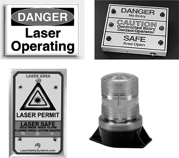
There is a common misconception that a laser power supply will turn an external warning on and off when the laser turns on and off. Some laser manufacturers may build in a function that permits this mode of operation, but this is a rare exception. The most common method of controlling the warning is through an interlock control system. In this mode of operation, the interlock is armed, it illuminates the warning, and it gives permission for the laser to operate. When the interlock is disarmed, the warning and the laser are secured. Figure 15.2 shows typical electronic warnings for a Class 3B or Class 4 laser area.
Figure 15.2
Typical electronic warnings used to designate a Class 3B or Class 4 laser area.
Engineered Area or entryway Safety Controls
Class 4 laser areas have the potential to be extremely hazardous to untrained and unprotected personnel and require stringent protection. ANSI Z136.1 gives a choice of three methods that can be used to mitigate the hazard:
Nondefeatable (nonoverride) area or entryway safety controls
Defeatable area or entryway safety controls
Procedural area or entryway safety controls
The nondefeatable and defeatable methods use engineered safety devices and are the preferred methods of controlling the laser hazard. The procedural method is not an engineered safety control method and is recommended only for limited specialized applications.
Nondefeatable Area or Entryway Safety Controls
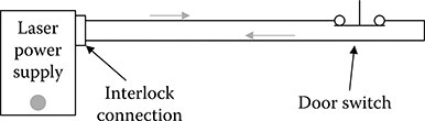
Nondefeatable means cannot be defeated. The nondefeatable safety circuit is the safest, simplest, and least-expensive type of engineered safety control. The interlock connection of a Class 4 laser (or shutter at the output of the laser) is connected to a safety circuit that extends to one or more limit switches at the entryway door. In operation, the circuit performs as follows: Open the door, and the laser turns off or the shutter closes.
Figures 15.3 and 15.4 show a greatly simplified version of a nondefeatable interlock configuration. In reality, the connections are more complicated because they must be designed to be fail-safe and fault tolerant. To design for these modes, the system designer must systematically walk through the circuit and ask: What would happen if this single item fails to open or shorts? When the answer does not yield a satisfactory result, the design is reworked. It is easy to see that a short across the main wiring in Figures 15.3 and 15.4 would create an unsafe condition. It is quite common to add redundant circuits as demonstrated in Figure 15.5 for this very reason. In the rare event of a failure of one switch, the second switch will do the job. The safety circuit is also expanded to perform secondary functions, such as control of the electronic laser warning.
Figure 15.3
Simplified electrical schematic of nondefeatable access control interlock with door closed. Laser is permitted to run (or shutter may open).
As Figure 15.5 shows, a single open or short failure in either circuit will not limit the ability of the system to perform the trip function. It is worthwhile to note that even in this circuit depiction, the final connection to the laser power supply is susceptible to a single-point fault condition if a short circuit appears across the connector. The external interlock system has been designed with fault tolerance, but the interlock provisions from the laser manufacturer still leave a small section of wiring that is not fault tolerant. In most laser applications, this is an acceptable risk, and the safety function is routinely checked by a laser safety audit, but when higher levels of fault tolerance are desired, a secondary means of shutdown is used. As an example, the first circuit might be connected to the laser power supply, and the second circuit may control the laser shutter. Thus, if either single circuit fails, the second circuit will still perform the safety function.
Figure 15.4
Simplified electrical schematic of nondefeatable access control interlock with door open. Laser cannot run (or shutter cannot open).

Figure 15.5
Redundant monitoring of dual door-limit switches provides enhanced protection.

This is just the tip of the iceberg when it comes to safety engineering, and many people are unaware of the complexities involved. A complete risk assessment for system design requires the evaluation of many factors, including risk estimation of the severity of potential injury, frequency of exposure, probability of injury, and analysis of personal protection equipment that can complement the safety measures.
How do we work with a nondefeatable interlock (Figure 15.6)? The laser operator enters the room and closes the door. The operator then will put on appropriate laser eyewear from the eyewear storage bin. The operator will arm the interlock. This will in turn cause the electronic warning outside the laboratory to illuminate and an interlock relay to close, which grants permission for the laser to start. The operator is now free to safely perform work with the laser, be it alignment or experiment with exposed Class 4 beams. Personnel outside the door are warned of the hazard by the beacon. If the door is opened, the laser will immediately trip off to prevent exposure. If the door is closed again, the system must be manually rearmed to start the laser.
The number one complaint of any laser researcher is the fact that many lasers are sensitive to thermal transients and have a long warm-up time before reaching a stable operating condition. To satisfy this concern, it is permissible to use a safety shutter connected to the room interlock system in lieu of the laser power supply.
The nondefeatable method sounds restrictive, and indeed it is, but it is also an extremely safe way of doing business. The nondefeatable method can be quite versatile when combined with Class 1 enclosure components. In this scenario, a simple Class 1 enclosure can be built around the laser table. An interlock switch must be built into the lid or door to this enclosure. The switch must be shorted when the enclosure is securely closed, and it must open if the enclosure integrity is violated. This interlock switch is then wired in parallel with the room interlock system, as shown in Figure 15.7.
Figure 15.6
An overhead view of a typical laser room outfitted with nondefeatable access control.

Figure 15.7
A Class 1 interlock sensor in parallel with a room interlock.
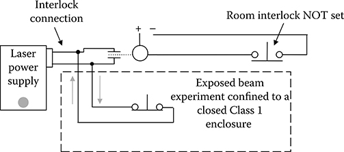
This system is now significantly more versatile. The operator can close the door, put on safety eyewear, set the room interlock, then open the enclosure and manipulate the experiment. Once the experiment is reconfigured, the enclosure is replaced, and the room interlock can be disarmed. The laser will remain in operation. Because the laser is contained in an interlocked Class 1 enclosure, there is no need for the electronic warning outside the door, and personnel can enter and leave the room as they desire. If someone attempts to open the enclosure without first arming the room interlock, the laser will trip. This mode of operation is ideal for experiments that may change on a daily or weekly basis but are required to run for extended periods without a trip. Indeed, an experiment could run for months at a time if needed. The only event that would trip the laser would be an event that violated the safety protocol.
The nondefeatable entryway control is the ANSI-preferred method of protection. It has the advantage of not requiring complex barriers or expensive laser curtains at the doorway because the door is the interlocked barrier. Commercial nondefeatable laser safety systems start at less than $1000.
Defeatable Area or Entryway Safety Controls
A defeatable safety control is a type of room interlock that allows authorized trained personnel to momentarily defeat (bypass) the interlock limit switches at a room entryway to enter and exit the room without interrupting laser operation. To be safe and effective, it is crucial that the level of laser radiation does not exceed the MPE at the entry point. This often requires the installation of barriers or laser curtains at the interior of the entryway. It is important to note that the ANSI Z136.1 standard recommends the defeatable interlock only if nondefeatable interlocks limit the intended use of the laser or laser system.
How does it work? As Figure 15.8 shows, the limit switch that monitors the door position can be temporarily bypassed by a relay contactor. A timer circuit holds this contactor closed for a set time period, typically 10–15 seconds. The timer is initiated by an input from one of the two locations, either a push-to-exit button from inside the room or an entry request from outside the room.
Figure 15.8
Simplified electrical schematic of a defeatable access control interlock.

Again, this circuit is overly simplified to present the general operating principle. A properly designed interlock system will have checks and balances to ensure that the timing circuit does not leave the interlock in a bypassed mode. If microprocessor controlled, the device should fail in a nondefeating manner if the micropro cessor quits. Some do-it-yourself systems have used security system keypads with built-in timers. Although failure is unlikely, they are typically not designed with fail-safe circuitry and have the potential to latch in the bypassed state that would leave the access control in an unsafe condition.
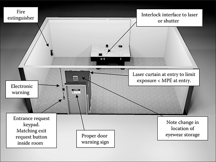
When comparing the defeatable to the nondefeatable access control, there is very little that has changed in the laser room. The changes are made at the entry-way. Most important is the necessity to limit the laser radiation exposure to a level less than the MPE at the entryway. The laser will be running when the door interlock is momentarily bypassed. The curtain shown in Figure 15.9 does not extend to the ceiling and floor or form a complete closure on the left side. This is acceptable if proper hazard analysis has shown that there are no specular or diffuse reflection paths that can divert the beam past the curtain and reach the MPE threshold.
The laser-protective eyewear storage bin has been relocated to the interior of the entryway. It could also be placed outside the main door, but theft and tampering are often a consideration. Following the defeatable entryway protocol, the laser worker would bypass the entry interlock, walk into the protected zone, and put on the laser eyewear before stepping into the main room.
When proper entry protocols are followed, the laser system can run indefinitely. The only conditions that would interrupt operation would be a power failure, a violation of the safety protocol, or a purposeful crash of the system.
Figure 15.9
A typical laser area configuration using a defeatable entryway control.
Hardware choices for defeatable access controls are as follows:
Laser curtain: The method of limiting the exposure at the entryway is not restricted to the use of commercial laser curtains. If it is possible to use barriers or deflectors at the location of the laser table, it would be preferable to placing barriers at the entryway. Trigonometry is our friend in this regard because a small barrier properly placed can create a large protected zone across the room. If analysis of the system will not support these small barriers, then entryway protection will be needed. Remember that drywall or sheet metal labyrinths are often an option. ANSI Z136.1 states (Section 4.6.4, p. 47):
Laser barriers shall be specifically selected to withstand direct and diffusely scattered beams and shall exhibit a damage threshold for beam penetration for an exposure time commensurate with the total hazard evaluation for the facility and specific application. Important in the selection of the barrier are the factors of flammability and decomposition products of the barrier material.
Entryway keypad or button: The ANSI standard does not specify a particular electronic method for granting access to the laser area. Keypads, electronic card readers, cipher locks, and key switch bypass certainly provide a superior level of administrative control. The key or code can be restricted to personnel who have been trained and authorized for access. Some facilities have used a simple pushbutton to activate the time delay for entry. This is less than ideal because it does little to limit access. The secret button is only a secret for a couple of days.
To magnetically lock or not to magnetically lock: Most commercial systems provide the option of magnetically locking the access door to the laser area. One could argue that the magnetic lock actually does very little from a laser safety standpoint; after all, the laser will trip off if the door is opened without first inputting the interlock bypass request. The opposing argument in favor of the lock is the fact that it guarantees that the door will not be opened unless the bypass request is given. This is a higher level of security, and it serves the function of limiting accidental trips of the interlock system. It is not difficult to imagine a researcher deep in thought reaching for the doorknob and opening the door before realizing the experiment was just tripped off because the exit button was not pushed.
The magnetic lock is chosen over other types of lock because it is a fail-safe device. It needs electricity to lock the door. When power fails or an electronic inter-lock circuit drops to a safe mode, the door unlocks. The magnetic lock is relatively simple to add to a door, and the electronic control makes it simple to add to an interlock system for access control. That being said, the magnetic lock also presents additional challenges that must be taken into account.
Looking at Figures 15.10 and 15.11, we can see the typical required elements when using a magnetic lock. Every door that has been magnetically locked must have a crash button on both sides of the door that will break power to the lock in the event of an emergency. These crash buttons must actually be in series with the power delivery to the lock, not simply telling a microprocessor that it should release power. There are several reasons for this requirement. One reason is in the unlikely event of an electrical malfunction of the interlock circuitry. Another is the need for emergency personnel to enter the room in case of fire or injury. Depending on your location, there may be a requirement to connect the magnetic lock circuit to the building fire alarm circuitry to automatically unlock the door in the event of fire. Finally, there are some localities that specify a no prior knowledge requirement for exiting a door with a magnetic lock. This requirement specifies that a single action will release the door. Figure 15.10 depicts a dual-action scenario. The push-to-exit button is depressed to release the lock, and the doorknob is turned to actually open the door. There are several options available to meet the single-action requirement, including crash bars with a built-in switch or look-down motion detectors that will automatically issue an open request when a person approaches the door. Each of these options adds to the complexity and cost of the system. In some cases, the requirement can be dropped by simply explaining the situation to the building authority who is asking for the no prior knowledge operation that the persons working in the laser area when the interlock is set will be highly trained or, at the very least, escorted by a highly trained individual; the training will include laser safety and operation of the laser safety system; and the premise of no prior knowledge is not realistic in this situation because everyone will have exposure to, and knowledge of, the proper operating procedures.
Figure 15.10
Detail of a defeatable access control exit.

Figure 15.11
Detail of a defeatable access control entrance.

The defeatable access control is significantly more versatile than the nondefeatable version. The added versatility comes at a price. If a laser area has multiple doors and the laser user has a need for a defeatable access, it is recommended that one door is selected for defeatable access, and the remaining doors are configured for nondefeatable operation. This is safer and more economical. Commercial defeatable interlock systems start at about $2500.
Procedural Area or Entryway Safety Controls
Where safety latches or interlocks are not feasible or are inappropriate, for example, during medical procedures and surgery, the following shall apply:
The ANSI Z136.1 (Section 4.3.10.2.2, p. 34) standard is clear. The procedural method is to be used only where the nondefeatable and defeatable interlocks are not feasible or are inappropriate. If someone is blinded by a laser at your facility, it would be a tough sell to tell an Occupational Safety and Health Administration investigative team that your budget was your reason for using the procedural method.
The example of the surgical laser is indeed one of the few appropriate cases for the use of a procedural method. The interlock exception is being granted to lasers used in medical procedures for the following reasons:
No one wants to inadvertently secure a laser in the middle of a medical procedure by tripping an interlock.
The flow of traffic in and out of a surgical area cannot be impeded when life safety is involved, so door locks or entryway switches are inappropriate.
The procedural entryway safety control method uses the following assumptions:
The laser is under the active control of an operator who can quickly secure the laser in the event of an emergency (supervised laser operation). This assumption is not stated as a line item in the ANSI standard, but can be inferred from the suggestion of a surgical laser.
All personnel are adequately trained and provided with personal protective equipment on entry.
The exposure must be less than the MPE at the entryway. Curtains, laser type, and room design are evaluated to meet this condition.
A visible or audible signal is provided at the entryway to indicate the laser is energized and operating at Class 4 levels.
Other than the surgical laser situation, there are few valid scenarios that can justify the use of the procedural area or access control protocol for a Class 4 laser area. It is worthwhile to note that even within ANSI Z136.3 (Safe Use of Lasers in Health Care Facilities), Sections 4.1 and 4.8 state that when a laser is not being used on a human patient, it shall be interlocked in accordance with the more stringent requirements of ANSI Z136.1.
Engineered Safety Training
Engineered safety training is a small subset of the overall training provided to the laser worker. Understanding the complexity of a laboratory can be a daunting challenge to a new student or employee. The laser worker must be taught about the particular nuances of the working environment. Lasers are often used in research laboratories containing a multitude of dangers. These systems often have multiple separate warning systems and emergency controls. For example, a room may contain a laser system, cryogenics, vacuum systems, and high voltage. Each system has its own dangers, so one might find warning strobes for laser hazard, oxygen-deficiency hazard, high-voltage hazard, and more. Beyond the individual hazards, there are often secondary hazards that appear through a combination of systems. For example, when a sufficiently high voltage is applied to a vacuum chamber, it is possible to generate X-rays. This new ionizing radiation hazard requires another safety protocol that must be enforced.
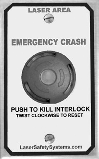
The training must address each of the hazards. It must explain the process to mitigate or eliminate the hazard in an emergency situation. If crash switches and warnings are a part of the various safety systems, it is vital that the switches be labeled or color coded to match the hazard type (Figure 15.12). There have been incidents in the past when users have been reluctant to crash an interlock system because they were unsure of the end result of depressing the poorly labeled crash button. The worker must be taught never to be afraid of pressing a crash button, even if it will result in downtime for the process or experiment. A crashed system is better than a person harmed.
Figure 15.12
An example of a crash switch with a purpose that is well defined by text. There can be no mistake that this button is intended to crash or safe the laser system.
Engineered Safety System Selection
It has been a common practice for many years to have on-site staff or students design and install laser interlock systems. This practice was viewed as a cost-savings measure and was often performed out of necessity because of the limited number of commercial system manufacturers. Be wary of technicians or students offering to design and install a system just because they tell you they can save you $1000. The time and effort required to reinvent the wheel is a resource expense. Sometimes, the costs involved actually end up exceeding the cost of a commercially available system. As these systems age and the original designers move or retire, the expansion, modification, or repair of the systems is placed in jeopardy if the system is not properly documented. If there is a commercially available product that fits your requirements, it will be worth the investment in the long run. A well-designed commercial system will last for the life of the laboratory and will be supported in long term with spare parts and documentation. The number of commercial manufacturers of laser interlock systems is growing, and products are becoming more versatile, so the argument to build your own system is getting weaker. Whichever route is chosen, it is imperative that the system is well documented.
The ultimate decision for selection of an engineered safety system should be a joint decision between the LSO and researcher. There will undoubtedly be situations for which commercially available systems are not adequate for the safety integrity level required. The LSO is encouraged to seek assistance from safety system manufacturers, peers, or professional safety consultants when there is any doubt over the proper course of action.
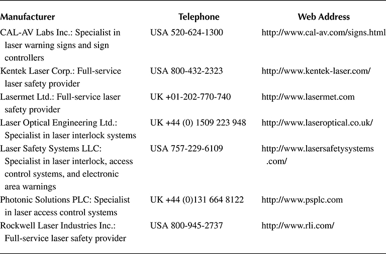
The following is a list of commercial laser interlock system and component manufacturers: