21
Free-Electron Laser Safety Challenges
Focus on the Jefferson Lab Free-Electron Laser
Introduction
The free-electron laser (FEL) technology dates back to the 1970s. When compared with conventional lasers, the significant difference lies with the laser medium. In the FEL, the laser medium is no longer a chemical, such as a gas or a crystalline structure, but an electron beam in an oscillatory magnetic field. Current FELs cover a wavelength range from millimeters to angstroms. The advantages of the FEL over conventional lasers include wavelength tunability and high powers that can be obtained in areas of the infrared and ultraviolet spectrum that have not been achieved using conventional lasers.
Applications that have benefited from use of FELs include biology, physics, medicine, and materials science. In the field of materials science, FELs can offer substantial cost and capability advantages, including advantages for high-volume materials processing over traditional manufacturing tools. FELs are being developed to process plastics, synthetic fibers, advanced materials, and metals as well as components for electronics, microtechnology, and nanotechnology. Prospective products include durable yet attractive polymer fabrics for clothing and carpeting; cheap, easily recyclable beverage and food packaging; corrosion-resistant metals with increased toughness; mechanical and optical components with precisely micromachined features; microcircuitry; and electronics for use in harsh conditions.
The price paid to achieve FEL-quality laser light is high. The conventional tabletop “black box” that houses the laser medium of a conventional laser must be replaced by an intricate facility that houses an electron beam accelerator and a magnetic field–producing device that causes the electrons to emit coherent light. The costs include the cost of construction, maintenance, and staffing. For this reason, most FELs in the United States are operated as federal or academic-funded user facilities.
In such facilities, the electron beam is usually created and accelerated using a large and complicated linear accelerator (linac). The beam of electrons is then sent through a periodic magnetic field known as a wiggler, where the light is produced. The light can be either recycled in a laser resonator or amplified to saturation in a single pass through a long wiggler. The wavelength of the light is a function of the electron beam energy and the strength and wavelength of the wiggler. Because of this, the FEL is very broadly tunable. Under the right circumstances, the accelerated electrons in the wiggler develop density modulations with an optical spacing (this phenomenon is referred to as microbunching). Over the length of the wiggler (or after multiple passes of the light through the wiggler), the electrons in the microbunches begin to oscillate in step (coherently), thereby giving rise to light with properties characteristic of conventional lasers. Because the electron microbunches can be less than a picosecond in length, the light generated comes in ultrashort pulses that can be used for strobe-like investigations of extremely rapid processes.
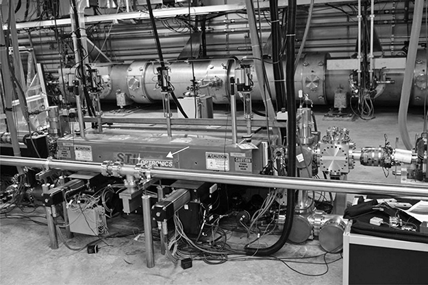
This chapter discussion is based on the FEL Facility at Jefferson Lab (JLab). At the JLab facility, the laser medium is isolated from the laser light laboratory. With effective isolation, the safety considerations can also be addressed separately; therefore this chapter will primarily address the safety considerations of the FEL laser laboratory and its interface with the laser medium (Figure 21.1).
Figure 21.1
Wiggler (arrow) and section of accelerator (metal cylindrical can in background).
Jefferson Lab Free-Electron Laser Facility
Description of the Facility
The JLab FEL Facility is located at the Thomas Jefferson National Accelerator Facility in Newport News, VA. The program and this user facility derive from the primary mission of JLab, namely, nuclear physics research and the world’s first large superconducting accelerator for generating continuous multibillion-volt beams of electrons, called the Continuous Electron Beam Accelerator Facility.
The FEL specifications are outlined in Table 21.1. A comparison of the FEL specifications with other light sources is presented in Figure 21.2.
Overview of the JLab FEL Components
The basic components of the FEL at JLab include the lasing medium, the beam transport and delivery system, and the laser laboratories.
Lasing Medium
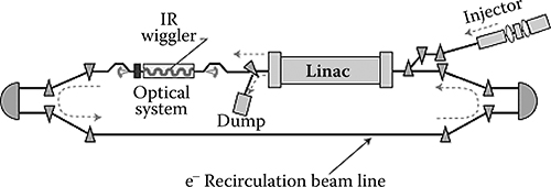
The electron beam accelerator and wiggler that serve as the laser medium are located in the basement of the facility, referred to as the vault. Figure 21.3 depicts a schematic view of the device. The JLab FEL is based on an energy-recovered linac. Electrons are released from the injector and are accelerated in a superconducting linac. After emerging from this linac, the electrons pass into a laser cavity that has a wiggler near its center. This wiggler causes the electrons to oscillate and emit light, which is captured in the cavity and used to induce new electrons to emit even more light. After exiting the optical cavity, the electrons then travel around the beam transport loop and back into the linac. There they give up most of their energy to a new batch of electrons, making the process highly efficient.
Table 21.1
FEL Specifications

Figure 21.2
Jefferson lab free-electron laser (JLab FEL) power versus conventional sources.
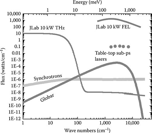
FIGURE 21.3
Schematic of a simple FEL beam accelerator and wiggler.
Laser Beam Transport and Delivery System
The laser beam delivery system transports the laser beam from the FEL to a series of laser laboratories. The beam is shared among the laboratories. Required components include the initial beam delivery pipe, optics control room (OCR), laser lab beam delivery pipe, mirror cassettes, and beam dump. All operations of the accelerator and laser laboratories are managed from a central control room.
Initial Beam Delivery Pipe
The laser transport system is generally a stainless steel vacuum line. This allows the beam to be transported with minimal losses even at wavelengths at which the air is strongly absorbing. The vacuum system must be properly designed with pressure relief valves and well-shielded high-voltage lines for the vacuum pumps.
Optics Control Room
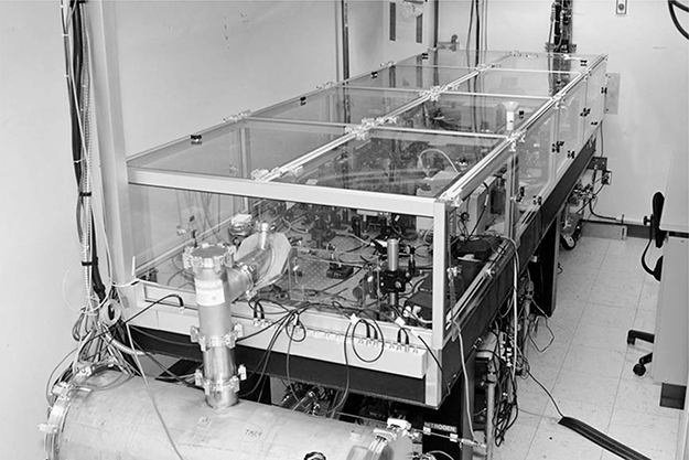
From the initial beam delivery pipe, the laser enters the OCR, where part of the beam is picked off for diagnostics, and the remainder is prepared for delivery to the laser laboratories (Figure 21.4). This is the first location where laser light is accessible on an optical table.
Laser Lab Beam Delivery Pipe
The laser lab beam delivery pipe is a stainless pipe under vacuum that transports laser light from the OCR to the laser laboratories.
Figure 21.4
Laser diagnostics table in optics control room.
Mirror Cassettes
Mirror cassettes are remote-controlled mirror systems that reflect the beam from the beam delivery pipe into the laser laboratory.
Beam Dump
The beam dump is located at the end of the laser lab beam delivery pipe. It is a water-cooled, copper cone coated with a low-reflectivity coating that can absorb up to 50 kW of laser light.
The control room (Figure 21.5) provides an area where all operations of the accelerator and laser laboratories are computer controlled.
Laser Laboratories
The second floor of the FEL houses the laser laboratories and radio frequency (RF) power supplies for the beam electron accelerator (Figure 21.6). Laser laboratory capabilities are provided to permit testing of various materials. Since the targets vary with each experiment, maximum flexibility in configuration of the facilities is desired. In each lab, control of the laser must be provided. Required light characteristics for each lab that can be manipulated include polarization, wavelength control, power control, pulse length, rastering, and focal spot waist and position.
Figure 21.5
Control room.

Figure 21.6
Laser laboratories on second floor. PLD is pulsed laser deposition. The microengineering lab operates in the ultraviolet. The laser delivery transport enters from the right and ends in the high-power dump (dark gray box). Gray areas are hutches. Small black boxes on the laser beam transport pipe are mirror cassettes.

Advantages of the JLab FEL
Advantages associated with the use of the JLab FEL are similar to those associated with most FELs. Since the gain medium only exists in the wiggler for a few nanoseconds and then leaves at the speed of light, there is no waste heat issue for FELs. Because of this they are, in principle, capable of producing very high average power. This power is available at any desired wavelength, and the wavelength can be continuously tuned using either the wiggler strength or the electron beam energy. The gain medium (the electron beam) is smaller than the optical mode (the laser beam). This leads to a repeated spatial filtering that results in an output beam with excellent optical mode quality. In FEL oscillators especially, the optical mode is a pure TEM00 mode. Because the gain medium exists in a vacuum, the laser is capable of operating at wavelengths where there are no transparent materials. In addition, if the experiment is mounted in a vacuum chamber, the light never needs to go through a window. This eliminates the need for a transparent window at the laser wavelength. Most FELs take advantage of high repetition rate picosecond or subpicosecond electron pulses as their gain media. The output is then a high repetition rate series of ultrashort, high-energy micropulses. This time structure is very effective for materials modification and processing.
Applications for the JLab FEL
Figure 21.7
Nanotechnology experiment. (From Mike Smith, NASA LaRC.)

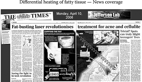
Currently, the JLab FEL Facility has seven laser laboratories. Experiments currently under study have applications in the manufacturing, nanotechnology (Figures 21.7 and 21.8), and medicine. To secure beam time at the FEL, an application is submitted and reviewed by committee. When an experiment is approved, actual experimental time is allotted at no cost to the user. In addition to the FEL, users can and do bring ancillary equipment such as magnets, furnaces, and other Class 4 lasers.
Figure 21.8
News coverage of FEL experiment in medical application research.
FEL Infrastructure
The required infrastructure for the JLab FEL includes physical structures and management systems for the laser medium, delivery system, and laser laboratories.
Physical Structures
Accelerator Vault
The vault (Figure 21.9) is a beam enclosure for the accelerator; there are several safety issues associated with the accelerator vault. Most significant is the existence of ionizing radiation. Whenever an electron beam is accelerated in a vacuum, bremsstrahlung (known as braking radiation) can be produced. An extensive radiation control program is required. The program includes shielding, monitoring, personnel entry control interlock system, and specialized training. RF radiation is required to accelerate the electrons, so an RF leak-tight waveguide delivery system must be used. Liquid helium must be used to achieve superconducting temperatures. Wherever the liquid helium is used, the potential for heat influx and subsequent evaporation and pressurization of the accelerating components exists. Pressure relief devices must be present to mitigate the explosion potential associated with overpressurization, and a program to manage oxygen-deficiency hazards (ODHs) associated with unexpected venting of liquid helium must be in place. The program must address requirements such as ODH assessments and controls, oxygen monitors, local exhaust, and training.
Figure 21.9
Cryomodule in the vault. Note the radio frequency (RF) waveguide coming from ceiling penetrations and terminating into the cryomodule (stainless-steel cylinder).
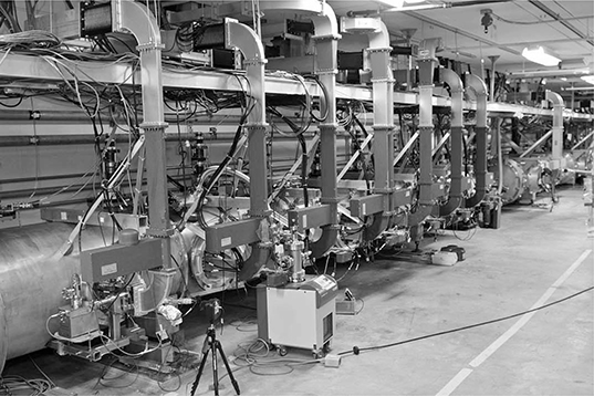
Figure 21.10
Electronic racks above penetrations on the second floor of the facility.
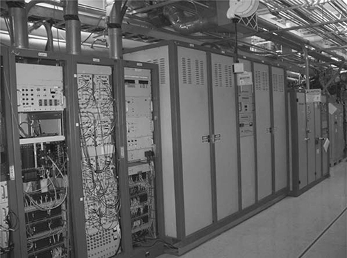
RF Gallery
The electronics (Figure 21.10) that drive the accelerator must be located outside the vault due to the potential for damage to electronics by ionizing radiation. The electronics and RF power supplies are located on the second floor of the facility. Cabling is fed down to the vault through penetrations. The most significant safety issue here is associated with exposure to ionizing radiation associated with the penetrations. A radiation safety program mitigates this issue. Electrical safety issues are also associated with the penetrations: Maintenance performed on such systems requires a lockout, tag-out program to control electrical hazards that present simultaneously both in the racks and in the vault. Another significant hazard is the potential for helium release to migrate from the vault up through the cabling penetrations to create oxygen deficiency, and this must be controlled by the ODH program.
Control Room
The control room (Figure 21.5) is located on the second floor of the facility. Operation of the accelerator is managed here. Control of the laser states and delivery of the laser beam to the laser labs is also managed here.
Optics Control Room
The OCR receives the laser beam from the optical transport system (Figure 21.4). It is from the OCR that the beam is delivered into the laser laboratories. A laser safety system now becomes necessary to control exposure to the laser beam. The OCR is accessed from the FEL Control Room. There are two purposes for the OCR. The first is to enable and disable the FEL. The second is to provide diagnostics to ensure that the correct beam will be received by the laser lab.
Laser Laboratories
All the light-tight laser laboratories receive the FEL beam through the laser lab beam delivery pipe. A beam dump is located at the end of the last laser lab. A mechanism to reflect the beam into each laboratory is needed; that mechanism is called a mirror cassette. A laser safety system is necessary in all laser laboratories.
Management Structures
The management structure for an FEL system is complex. The JLab FEL Line Management is responsible for the safe operation and maintenance of the facility; for planning, review, and acceptance of user experiments; and for providing vision for the future applications of the FEL. Key positions that exist include
Associate Director
FEL Facility Manager
Safety Officer
Laser Safety Officer
An optimal organizational structure for the FEL includes the following groups:
Operations Group: The operations group operates the control room. This group is responsible for the operation of the accelerator, the laser delivery system, and the state of laser operations in each laser lab.
Accelerator Systems Management: At least seven subgroups are required for adequate management of the accelerator.
Safety Systems Group: It is responsible for the control of prompt radiation associated with the accelerator. Since the laser medium is a high-energy electron beam, it must be situated in a radiation-shielded enclosure. Radiation controls must be in place to prevent any inadvertent radiation exposure. A personnel safety system must be installed to ensure that no one is in the electron beam accelerator enclosure during beam operations. Systems that this group installs and maintains include the controlled access system for the vault, run/ safe crash boxes (Figure 21.11), controls to maintain the accelerator in beam permit and high-power permit, and the oxygen-deficiency detector and alarm system that must exist in the facility due to the use of liquid helium to support the superconducting state of the accelerator.
Instrumentation and Controls Group: This group is responsible for all equipment used to start, optimize, and operate the accelerator and the laser beam.
RF Group: The electron beam is accelerated by RF power. Associated klystrons (50 kW for the FEL accelerator; Figure 21.12) and power supplies are managed by this group.
Injector Group: The injector is the source of the electrons for the accelerator. This group must maintain the photocathode electron gun (Figure 21.13), along with its high-voltage power supply and vacuum system.
Cryogenic Group: This group maintains the liquid helium supply required for the superconducting accelerator.
Vacuum Group: This group maintains the vacuum system required for the accelerator and beam transport system.
Facility Management: The mechanical engineering group for utilities ensures that all nonbeam safety controls are functional. Examples include chemical fume hoods and fire protection system.
Figure 21.11
Run-safe box—part of the personnel safety system in the vault.
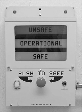
Figure 21.12
One of the klystrons used to produce RF for the accelerator. Klystrons are located in the RF gallery (second floor). The power supply is in an adjacent electronics rack (see Figure 21.10).
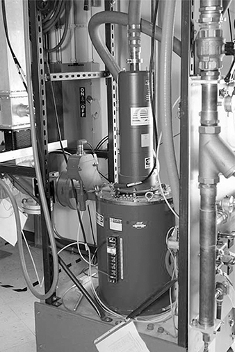
Figure 21.13
Schematic of the electron gun; note that a Class 4 drive laser is used to interact with the cesiated photocathode to produce free electrons.

Laser Safety
The laser safety system for an FEL is complex. Key positions necessary to maintain and inspect this system are the following:
Laser Safety Officer: Provides independent oversight to the laser safety program.
Laser System Supervisor: Normally a physicist with a doctoral degree, the laser system supervisor is responsible for the overall operational safety of the FEL laser beam.
Laser Interlocks Manager: Normally this position is held by an electrical engineer who is responsible for maintaining the laser interlocks associated with the FEL and any other Class 3B or 4 laser used in the facility.
FEL Laser Operator: An FEL employee that has full control of the beam delivery to each lab.
Laser Safety Hazards and Controls Specific to the FEL
There are hazards that must be considered with the FEL. These hazards are related to the control of laser light to multiple laser laboratories, extremely high power, the presence of harmonics and tunability, and the presence of a user population that is generally transient.
Control of Laser Light to Multiple Laser Laboratories
The FEL is located in the accelerator vault. Once the laser light is generated, a complex system of shutters becomes necessary.
Shutter Configuration
The FEL laser beam needs seven or eight pieces of equipment to be moved to transport the laser light into the lab. The first two are a pair of FEL shutters located in the FEL optical cavity in the vault. Inserting either of these shutters greatly increases the losses in the FEL cavity and shuts off the laser. The third is a high-power shutter that sends the beam into a diagnostic power meter. This must be withdrawn to send the laser light into the optical transport. The fourth is a collimator mirror cassette that has an open position allowing experiments to be carried out in the vault. If the mirror cassette is moved to a position with a mirror, the beam is sent upstairs into the OCR. In the OCR is another higher-power shutter that, when opened, allows beam into the laser laboratories. This is the fifth shutter. The sixth shutter is a mirror cassette that must be off its home position to send the beam into a specific lab. In the home position the light is passed onto the next lab. The seventh shutter is the specific lab shutter, which must be withdrawn to send beam into the lab. In laser labs with a hutch there is one more shutter that allows the beam going into the hutch to be shut off (the hutch bypass shutter). The hutch bypass shutter is tied to the lab shutter so that one always has two shutters between the user and the beam. The user only has control of the seventh and eighth shutters.
Shutter Configuration Control
The FEL shutter is interlocked to the vacuum for the beam delivery lines, so the FEL cannot be operated with the beamline in an incomplete (especially open) state. All optical transport vacuum pipes are labeled as such and are not to be opened without permission from the optical transport system owner. Any attempt to open the transport line results in a vacuum loss, which will shut off the laser.
All the laser optics and the transport optics are remotely controllable via a Programmable Logic Controller–based control system. The FEL operator usually controls these systems from the FEL control room and has sole control over the first six shutters. Only the FEL operator can provide the enabling voltage for the lab shutter. The user must be able to lock out the lab shutter, however, if it is necessary to prevent the laser from entering the lab. This may be accomplished by locking out the FEL shutter in the lab. Only the user can operate the hutch bypass shutter, though the FEL operator can monitor its state.
High Power
The FELs are capable of producing very high power. There is potential for devastating injuries associated with both eye and skin exposure. Small specular reflections from beamline elements can be as large as Class 4 by themselves. If the laser is operated in the ultraviolet, the user will generally want to keep the beam enclosed due to the severe skin hazard. When the laser is operating at kilowatt levels, the nominal hazard zone for even dermal exposure from scattered light can be quite large. These conditions necessitate establishment of an exclusionary area for operations at full power.
Configuration
The established states for the laboratories are listed in Table 21.2 and described here:
Open: When all status lights are off, anyone can enter. The lab contains no Class 3B or Class 4 laser hazards. Many nonlaser hazards may still be present.
Hutch Mode: During hutch mode, a light-tight hutch is used to contain the laser. Personnel may be present in the laser lab during hutch mode. The hutch must have engineering controls to keep personnel from entering or opening the hutch when laser light is present.
When the lab is in hutch mode, a green (laser users only) lamp is illuminated on the door, and any laser user approved for the lab can enter after presenting an electronic radio frequency identification card (RFID card or smart card) to the card reader next to the door. The maglocks and the door interlocks are bypassed for 15 seconds after the card is accepted. If the door remains open after this delay, the lab interlock system will crash. If an approved user does not have a working smart card, they may ring the doorbell next to the lab door and have someone inside the lab let them in using the Exit button on the inside of the door. Users needing to leave the lab may also press the Exit button to leave the lab. Again, the maglocks and door interlocks are bypassed for 15 seconds when this is done.
Table 21.2 Summary of the Allowed Access States for the Laser Labs
Light on Door | Access State | Laser Protection | Other Requirements |
None | Open | None required | None |
Approved users only (green) | Hutch | Class 1 laser enclosure | Hutches interlocked/floor mats |
Goggles required (yellow) | Alignment | Laser safety eyewear required | Harmonic blocking filter inserted |
No access (red) | Exclusionary | Sweep procedure must be followed | Check beam paths before sweep |
Alignment Mode: When the yellow light (goggles required; see Figure 21.14) is illuminated on the door, the lab is in alignment mode. In this mode, any approved laser user may enter the lab using a smart card or after being let in by another approved user. It is essential to wear laser safety eyewear when the yellow light is on. The maglocks and door interlocks may be temporarily bypassed using the smart card reader or the Exit button when the lab is in hutch mode. There are three submodes in alignment mode: Local Laser Mode: This mode allows for the use of ancillary conventional lasers not related to the FEL. It is selected using the local laser/FEL mode key. When in this mode, the lab shutter and the mirror cassette are locked out so that FEL light cannot be delivered to the lab. The lab will stay in alignment mode even when the accelerator is running continuous electron beam. Only local lasers may run, and laser safety eyewear is required at all times. The interlock system will allow only this mode to engage if the mirror cassette is in the home position.
FEL Mode: The FEL light can be delivered to the lab as long as the accelerator is in a limited duty–cycle state, which reduces the average power so that laser safety eyewear can be specified.
HeNe Alignment Mode: It is possible to operate the system with an upstream ultraviewer Class 3R helium–neon (HeNe) laser. The upstream HeNe laser can then be used to align an experiment. An FEL operator must activate HeNe alignment mode using a key in the OCR. Exclusionary Mode: When the red (no access) light is illuminated on the door, no access is permitted. The lab is in exclusionary mode. If a smart card is presented to the card reader, the maglocks and door interlocks are not bypassed. The Exit buttons crash the lab in this mode.
Configuration Control
The operating mode of each individual lab is set by the FEL operator using the keys in the laser labs and the OCR. The state of the labs can be monitored from the FEL control room. The control system must make it clear at a glance where the FEL beam is being sent at any time. The controls used include an interlock system, an administrative procedure to activate the interlock system, and a communication system between laser operator and users.
Figure 21.14
(Left) Example of a small hutch in a laser lab with one interlocked cover removed. (Right) Entry status lights when in hutch mode.

The interlock system is adapted to each laboratory. The interlocks are designed in accordance with American National Standard for Safe Use of Lasers (ANSI Z.136.1) specified by American National Standards Institute (ANSI). In addition to those requirements, the interlock system must have the following:
Redundant Interlocks: Two shutters or insertable mirrors must be in place between any personnel and the full-power FEL beam at all times and between any unprotected personnel and alignment mode or full-power beam. Failsafe Laser Shutters: The shutter that turns off the FEL must be failsafe in that the loss of either power or air must close the shutter. The power for the shutter must come from the interlock system.
Provision for Separate Class 3B or 4 Lasers: Lasers are interlocked to the lab interlock system so that they cannot be operated unless the lab is secured. If the lab drops to an open state, the lasers must be disabled from lasing or must drop to a Class 1 state.
Interlock Beam Stops to Water Flow: All laser beam stops must have temperature interlocks that shut the laser beam off if the external beam stop temperature exceeds 60 °C.
FEL must be interlocked to transport vacuum integrity. If the pressure in the optical beam delivery pipe exceeds 10 mm Hg, the FEL must be disabled so that the light cannot be transported into the laser labs. All vacuum pipes must be labeled so that they are not disconnected during operation.
Administrative Interaction with Interlock System: Prior to engaging the inter-lock system, the laboratory must be cleared of all personnel. An administrative sweep of the room ensures that no personnel remain. The sweep path (Figure 21.15) is designed to incorporate physical interaction of the sweep personnel with the interlock system (Figure 21.16) in the form of sweep buttons that are located at several key points in the laboratory. This at least ensures that the sweeper has fully traversed the lab. At the end of the sweep, a complete sweep button must then be depressed, and the sweeper exits the lab. Warning lights both inside and outside the room and an alarm clearly audible throughout the inside of the room under normal operating conditions must activate.
Communication System: The door for each lab has three status lights indicating whether the room is in hutch mode (green), alignment mode (yellow), or exclusionary mode (red) or open (no lights illuminated). The laser operator in the control must be in continuous communication with the laser user for FEL operations.
The operating lasers and wavelengths must be selected when the lab is made up. The permissive buttons are selected at the entrance to the laser lab. The buttons are the interface to a programmable logic controller. The controller will not permit use of two lasers with conflicting eyewear requirements (Figure 21.17). This ensures the user to select appropriate eyewear before entry.
Figure 21.15
Schematic of sweep path in one of the laser labs at JLab. The Laser Personnel Safety System (LPSS) interlock chassis shown in Figure 21.16 is to the right of the door. A typical sweep button is shown on the right.
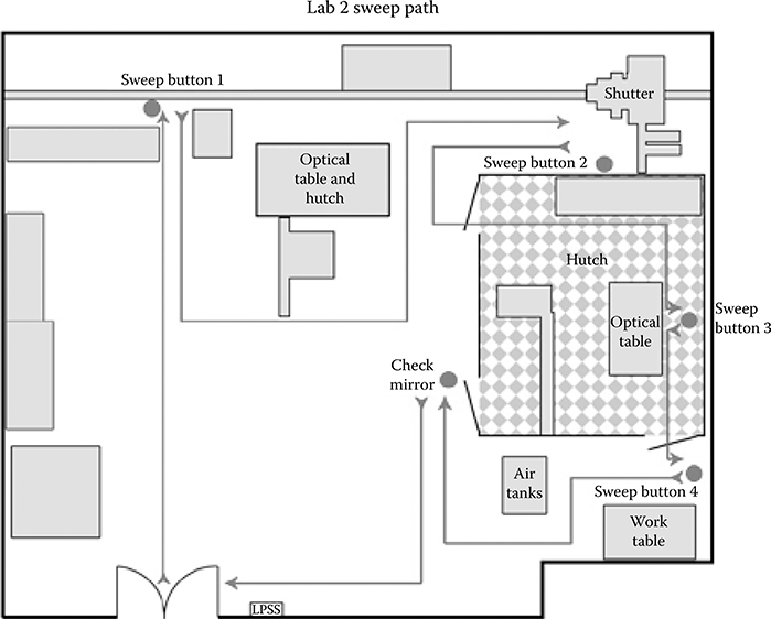
Figure 21.16
(Left) LPSS interlock chassis with crash button and sweep initiate button. (Right) Sweep button. When the “Ready” light is lit, one can press the button to arm the box.

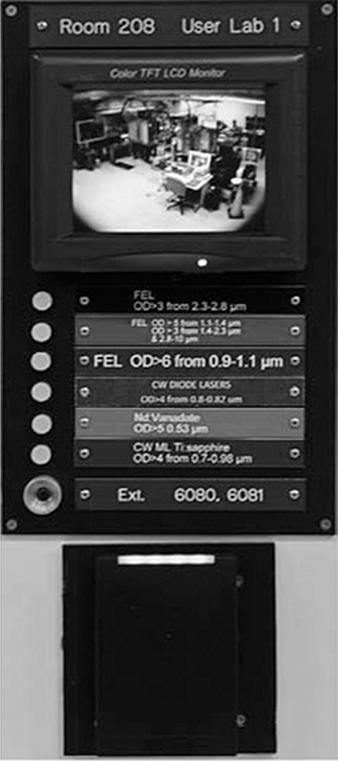
Figure 21.17
State-of-the-laboratory display for a laser lab (User Lab 1) located outside entrance door. Note real-time video display of interior of room. White buttons have laser system identified next to them; when illuminated, the system is to be expected to be lasing, and safety eyewear requirements are displayed adjacent to each button. At the bottom is the radio frequency identification card reader for the room electronic access system.
Harmonics
The FELs are unique in producing strong, partially coherent beams at all harmonics of the lasing wavelength (Figure 21.18). The second and third harmonics can be as large as a percent of the fundamental power. The harmonics have almost complete transverse coherence and are therefore considered as laser light. The fourth and fifth harmonics are generally smaller but may be as much as 0.1% of the power of the fundamental. Since the fundamental is tunable, the harmonic might be at any wavelength in the visible.
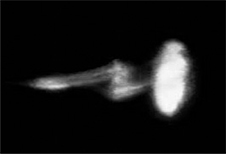
Figure 21.18
Fifth, sixth, and seventh harmonics during 3 μm FEL operation dispersed in a prism.
When operating at near-infrared wavelengths, the user must either block out all harmonics or use “virtual” laser-protective eyewear that takes advantage of virtual reality goggles developed for gaming tied to small cameras on the goggles. An example of a harmonic blocking filter is a gallium arsenide plate that stops all light with wavelengths shorter than 800 nm.
Tunability
The wideband tunability spans many damaging regions of the spectrum. It is imperative that the state of the laser with respect to the fundamental wavelength selected is detectable and controlled.
Cultural Differences of User Community
Because of the high cost of overhead associated with the electron beam accelerator laser medium, FELs are generally operated as user facilities; their operation is similar to synchrotron light sources. The infrastructure support group must maintain vigilance over the maintenance of the engineering controls and ensure strict compliance with administrative controls. This vigilance results in a tightly structured and documented safety program. This mode of operation is quite different from a typical single user in a university lab. The users must adapt to a structured and documented safety regime.
Elements Of The Laser Safety Program Unique To The FEL
The FEL Facility requires engineering and administrative controls to ensure the safety of the user and the infrastructure staff. In addition to the elements of a laser safety program specified by the ANSI American National Standard for Safe Use of Lasers (ANSI Z136.1), the laser safety program requires an approval process for experiments to be performed at the facility and a robust laser safety interlock system coupled to administrative controls.
Laser Safety Training
There are two courses required to become a laser user. The first is given by the Laser Safety Officer and must meet ANSI standard requirements. The student must pass a written test. The second set of training is FEL specific. It consists of training on the facility in general and on the specific lab and experiment to be used. The user must pass a written test specific to the laser laboratory in which they will be working.
FEL Experiment Review Process
An experiment consists of four phases: proposal, setup, run time, and decommissioning.
During the proposal phase, the safety requirements are identified by the user lead scientist using the Experiment Safety Approval Form (ESAF; see Appendix). This form allows for a preliminary hazard analysis: It identifies the target material, optical setup, required optics and beam dumps, and lists any chemicals and ancillary equipment that may be required for the experiment. The form also allows for identification of significant environmental aspects that would be associated with the experiment, such as discharges to air or sewer and waste generation. The ESAF is reviewed by the Technical Advisory Committee (TAC) appointed by the facility manager. The team consists of the laser safety officer, the laser system supervisor, and the safety officer. Other safety expertise may be required, such as the facility fire protection engineer or industrial safety representative.
During the setup and before runtime, a physical inspection is conducted by the TAC and any other required safety experts. Examples of issues that may need correction include the following (for a complete list see the Task Hazard Analysis form in the Appendix, form 3130-T3):
Ancillary equipment such as magnets may not have all interlocks and electrical barriers installed. Such equipment must be inspected to ensure that its installation meets electrical and fire safety codes.
Users may have brought respiratory protection to the facility. Evidence that the user home institution has an Occupational Safety and Health Administration compliant respiratory program, that the respirator is necessary for the experiment, and that the respirator user is trained and fit tested may be required. In most cases, substitution of facility engineering controls will be required.
Any Class 3B and Class 4 lasers brought by the user must meet Center for Devices and Radiological Health requirements; users may have “fabricated” diode lasers from laser components that do not meet these requirements.
During an experiment, the laser operator must maintain close communication with the laser user during FEL beam delivery. During and after decommissioning, the TAC must inspect to ensure that the laser lab is left in a safe state.
Controls Summary
The laser safety interlock system is robust. In addition to the system, administrative controls are required such as
Laser Operational Safety Procedures in place for each laboratory.
Procedures for each experiment must be reviewed and approved.
The laser operator must be present in the Control Room during FEL operations. The FEL operator is a JLab employee trained to operate the electron beam accelerator and deliver beam through the OCR. The operator is an independent observer of the experiment.
Permission to use the laser can only be issued by the FEL operator, who has available video camera monitors of each laboratory.
Routine safety oversight must be provided. The user must be supervised by the FEL operator to ensure that administrative controls are followed.
Future Of The FEL
New facilities designed specifically to produce X-rays are under construction. It is expected that additional operational and safety requirements will evolve along with this capability.