
11 Mixing in Logic
WHENEVER YOU HAVE MORE THAN ONE TRACK IN YOUR DAW, you will have to mix together the different tracks so you can hear all the various tracks out of the same set of speakers or headphones. The simplest form of mixing is when you sum (in other words, add the different audio streams of) all your audio to the same outputs so all your different tracks play from the same speakers. For example, you could take a song with material on 16 different audio channels and combine them into a single stereo output so you can listen to all 16 channels through your stereo monitors. After you do this, your audio will have been mixed together. However, mixing music is far more of an art than simply that. You can adjust the volume and position of your audio in a stereo or surround panorama for each track. You can process your tracks through effects individually or in groups. You can process the song as a whole through effects. And, of course, you can bounce—or print—the mix to a single audio file.
Logic offers some of the most comprehensive and intuitive options and features for mixing that are available in the digital realm. Logic can build a mixer for you from the tracks you have in your main window, or you can build your own mixer in the Environment. You can route your audio directly to your outputs or use myriad creative methods to group tracks for mixing and processing. You can insert effects directly into a given audio track, send your audio to other channels for processing, or change the output of your tracks to group them with others for processing. You can bounce your audio down to a file in real time so you can hear exactly what is going into the file, or you can bounce the audio offline when you know exactly what you have and you don’t need to hear it again. Logic does all this using channel strips that offer you a complete view of each track’s settings at a glance.
This chapter will not teach you how to create a professional radio-ready mix of your music. It will, however, explain how you can use Logic to achieve the best mix you can and offer some techniques for using Logic to mix in creative and exciting ways.
Mixer or Mixer Layer?
As discussed, channel strip objects in Logic show a complete channel strip reminiscent of a hardware mixer channel strip. Logic gives you two options for how you can arrange these channel strips. The first is to allow Logic to put together your mixer for you. As mentioned in Chapter 3, “The Logic Project,” Logic creates a mixer, called—wait for it—the Mixer, based on the tracks you have in the main window. The other way you can create a mixer is to do so manually, by adding your own channel strip objects to the Mixer layer of the Environment window and organizing them yourself. Each method has its advantages and disadvantages, and they are not mutually exclusive; because any channel strips in the Mixer represent channel strip objects in the Environment, both mixers coexist in the same project. You may prefer to access either or both, depending on your workflow and the specific project on which you are working. The specific features of each mixer are described in this section.
The Mixer
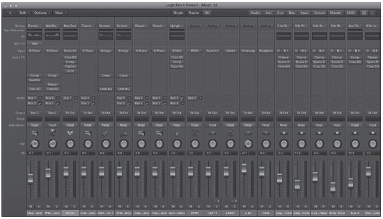
The Mixer is a very powerful tool in Logic. Not only does it reflect all of the MIDI and audio tracks you have in the main window, but it automatically reflects all channel strip objects in your project that you have created in the Environment. You can access the Mixer from the Window global menu by selecting Window > Open Mixer or by pressing the key command Command+2. You can also open it inside the main window by pressing X. Figure 11.1 shows the Mixer window.
Figure 11.1 The Mixer reflects all the tracks you have in your project.
© Apple Inc.
One of the best features of the Mixer is that Logic automatically configures it for you. There is no setup at all to do. As you add tracks to the main window, the Mixer automatically reconfigures, too. Also, the Mixer is the only mixer screen that shows MIDI channel strips, so if you use a fair number of MIDI tracks, the Mixer allows you to see channel strips for your MIDI tracks alongside your audio channel strips.
You can use the channel strip Filter buttons at the top of the Mixer to filter the types of channel strips in the Mixer (omit the audio tracks, instruments, outputs, MIDI tracks, and so on). You can also use the Single, Arrange, and All View buttons to change your view in the Mixer.
The Mixer’s biggest weakness is that it is limited to only a single horizontal row of channel strips. You could, however, open multiple Mixers, each set to a different channel strip type, and arrange them as you see fit. Also, if you want to rearrange the order of tracks in the Mixer, you’ll need to reorganize the tracks in the Tracks area.
The Mixer Layer of the Environment
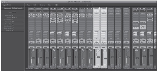
You can create channel strip objects in the Environment. By simply adding multiple channel strip objects in the Environment window, you can create your own custom-configured Environment Mixer layer. The Layer menu includes a command to open the Mixer layer; this command opens an Environment window to the Mixer layer of the Environment. Normally, this is where Logic keeps all your channel strip objects, but if you create your own Mixer on a new layer, the Mixer Layer command will not open your custom mixer. The Mixer layer in the Environment can have any shape you want and can include as many or as few channel strip objects in any given layer as you want (with the caveat, of course, that all the tracks in your song will have objects created for them on some Environment layer). Figure 11.2 shows the Mixer layer of the Environment for the same project as in Figure 11.1.
Figure 11.2 The Mixer layer of the Environment offers great flexibility but doesn’t automatically adapt to the tracks in your main window like the Mixer does.
© Apple Inc.
The main advantage of building Mixers in the Environment is that you can create and organize them however you like, allowing your Mixer to reflect exactly how you want to work. The Mixer layer does not reflect your main window, however. This can create extra navigation headaches. For example, if your Mixer layer contains 64 audio track channel strips and then three software instrument channel strips, but your song uses only 16 audio tracks and two software instruments, you’ll have to scroll from audio track 16 through 48 empty audio tracks to your three software instruments—or continually create Mixer layers reflecting what your song looks like. By contrast, the Mixer can be filtered to contain only your 16 audio tracks, so you’ll have no extra tracks to navigate. On the other hand, in the Mixer layer, you can instantly rearrange any of the objects, so you can simply move your Mixer around or open new layers for different channel strip objects. Of course, because the Mixer layer contains only channel strip objects, it does not show you any of the external MIDI tracks in your Tracks area. The Environment channel strips also lack certain features available in Mixer channel strips, like access to MIDI FX on software instrument channel strips and the Compressor/Limiter Gain Reduction meter, which you’ll learn about later in this chapter.
Adding Input Channel Strips
Although most audio tracks can be added to your Logic project in the main window, input channel strips still need to be added in the Environment. In the Mixer layer of the Environment, open the New local menu and choose Channel Strip > Input. A new input channel strip object will be created in the Mixer layer.
You can add as many mono input channel strips as your audio interface has inputs. If you change an input channel strip’s format to stereo, it will use two of your audio interface’s hardware inputs. Therefore, if your audio interface has eight inputs, you could have eight mono input channel strips in Logic, four stereo input channel strips, or any other combination of stereo and mono input channel strips that does not exceed your audio interface’s eight total hardware inputs.
What’s in a Name?: Although Logic Pro is full of many great features that have simplified previously tedious and confusing tasks, possible new sources of confusion are the names Mixer and Mixer layer.
In earlier versions of Logic, the Mixer was known as the Track Mixer, and it reflected only what was in the Arrange window (now called the main window). The Mixer layer of the Environment was known as the Audio Mixer, and it was where you needed to create and configure your audio objects (now known as channel strip objects), which you could then transform into the kind of customized workspace for which Logic is famous. The problem back then was that you needed to add all your audio objects to the Arrange window to have access to them in the Track Mixer, and you didn’t have access to MIDI tracks in the Audio Mixer.
Now, in addition to the ability to quickly and easily create any type of track in the main window and have that reflected in the Mixer, the Mixer also automatically reflects anything you add to the Mixer layer of the Environment. The Mixer layer, on the other hand, is still crippled by its inability to incorporate external MIDI tracks, among other things. That means the Mixer will be your preferred mixer in Logic, with the Environment’s Mixer layer being reserved for special customization and incorporation of Environment widgets.
The problem is keeping track of which Mixer is which. Unless I state that something is to be done in “the Mixer layer of the Environment” or in some way refer specifically to “the Mixer layer,” then “the Mixer” refers to the Mixer that opens in its own window or inside the main window, with its own local menus.
The Mixer Local Menus
Like all windows in Logic, the Mixer includes its own local menus with commands specific to itself. The following sections describe the Mixer local menus and their options.
The Edit Menu
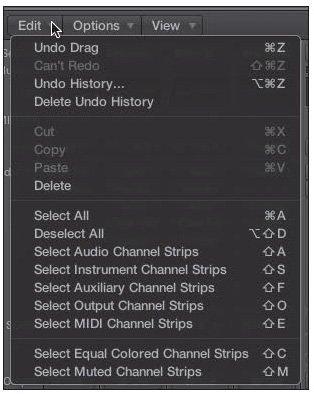
The Mixer Edit menu contains the typical Edit menu commands, but it does add a few Mixer-specific commands, which you can see in Figure 11.3.
Figure 11.3 The Mixer Edit menu.
© Apple Inc.
The unique Mixer Edit commands are pretty self-explanatory, offering commands for the selection of specific channel strip types, such as Select Audio Channel Strips, and two other commands for selecting particular groups of channel strips:
![]() Select Equal Colored Channel Strips: This selects all channel strips of the same color as the currently selected channel strip. The key command for this is Shift+C. You can assign colors to your channel strips by opening the Colors window (the global View > Show Colors path, or Option+C), selecting a channel strip, and clicking on a color. This also updates the associated track color in the Tracks area.
Select Equal Colored Channel Strips: This selects all channel strips of the same color as the currently selected channel strip. The key command for this is Shift+C. You can assign colors to your channel strips by opening the Colors window (the global View > Show Colors path, or Option+C), selecting a channel strip, and clicking on a color. This also updates the associated track color in the Tracks area.
![]() Select Muted Channel Strips: This selects all muted channel strips. The key command for this is Shift+M.
Select Muted Channel Strips: This selects all muted channel strips. The key command for this is Shift+M.
The Options Menu
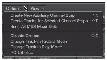
The Options menu consists of a few miscellaneous functions you may want to use. Figure 11.4 shows the Options menu of the Mixer.
Figure 11.4 The Options menu of the Mixer.
© Apple Inc.
Here are brief descriptions of these functions:
![]() Create New Auxiliary Channel Strip: This command creates a new auxiliary channel strip. The key command for this is Control+N.
Create New Auxiliary Channel Strip: This command creates a new auxiliary channel strip. The key command for this is Control+N.
![]() Create Tracks for Selected Channel Strips: This command adds any selected Mixer channel strips to the Tracks area. For example, you can use this command to add aux tracks to the Tracks area from aux channel strips in the Mixer. The key command for this is Control+T.
Create Tracks for Selected Channel Strips: This command adds any selected Mixer channel strips to the Tracks area. For example, you can use this command to add aux tracks to the Tracks area from aux channel strips in the Mixer. The key command for this is Control+T.
![]() Send All MIDI Mixer Data: This command sends all the Mixer-related information that is on MIDI tracks to your MIDI devices.
Send All MIDI Mixer Data: This command sends all the Mixer-related information that is on MIDI tracks to your MIDI devices.
![]() Enable/Disable Groups: This command allows you to temporarily disable groups and reenable them. Groups are covered in detail in the section “Mixer Groups” later in this chapter. The key command for this is Shift+G.
Enable/Disable Groups: This command allows you to temporarily disable groups and reenable them. Groups are covered in detail in the section “Mixer Groups” later in this chapter. The key command for this is Shift+G.
![]() Change Track in Record Mode: If you select this option, changing a setting on any channel strip while recording automatically selects that track. If you keep this option deselected, you can change the settings on any channel strip during recording without changing the track that is selected.
Change Track in Record Mode: If you select this option, changing a setting on any channel strip while recording automatically selects that track. If you keep this option deselected, you can change the settings on any channel strip during recording without changing the track that is selected.
![]() Change Track in Play Mode: If you select this option, changing a setting on any channel strip during playback automatically selects that track. If you keep this option deselected, you can change the settings on any channel strip during playback without changing the track that is selected.
Change Track in Play Mode: If you select this option, changing a setting on any channel strip during playback automatically selects that track. If you keep this option deselected, you can change the settings on any channel strip during playback without changing the track that is selected.
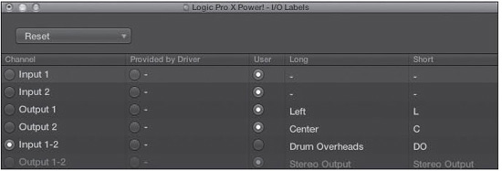
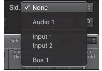
![]() I/O Labels. This command opens the I/O Labels window, shown in Figure 11.5. In this window, you can assign names to your inputs, outputs, and buses, which can be provided by Logic (channel), your driver, or you. Double-clicking in the Long and Short columns allows you to assign long and short user I/O labels. The Reset menu gives you options to reset all the labels or to reset them by specific channel type: input, output, or bus. Note that these labels are a global setting and will apply across all projects. You can also access this window by selecting Mix > I/O Labels.
I/O Labels. This command opens the I/O Labels window, shown in Figure 11.5. In this window, you can assign names to your inputs, outputs, and buses, which can be provided by Logic (channel), your driver, or you. Double-clicking in the Long and Short columns allows you to assign long and short user I/O labels. The Reset menu gives you options to reset all the labels or to reset them by specific channel type: input, output, or bus. Note that these labels are a global setting and will apply across all projects. You can also access this window by selecting Mix > I/O Labels.
Figure 11.5 The I/O Labels window.
© Apple Inc.
NOTE: The Mix menu was discussed in Chapter 10, “Using Automation in Logic.” Mix menu commands that were not covered in Chapter 10 will be covered later in this chapter.
The View Menu
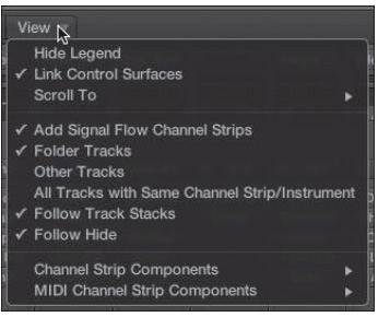
The View menu offers a number of options that relate to MIDI tracks and the overall look of the Mixer. Figure 11.6 shows you the View menu.
Figure 11.6 The View menu of the Mixer.
© Apple Inc.
The various options in the View menu are as follows:
![]() Show/Hide Legend: This command lets you toggle the Mixer’s legend, which can be seen at the far left of the Mixer in Figure 11.1.
Show/Hide Legend: This command lets you toggle the Mixer’s legend, which can be seen at the far left of the Mixer in Figure 11.1.
![]() Link Control Surfaces: If you have a hardware control surface connected to Logic, selecting this option ensures that the track selected in the Mixer always reflects the channel you have selected on your control surface.
Link Control Surfaces: If you have a hardware control surface connected to Logic, selecting this option ensures that the track selected in the Mixer always reflects the channel you have selected on your control surface.
![]() Scroll To: This submenu includes options that allow you to jump to various track types in your Mixer. It includes the same group of track types as the channel strip filter buttons. These navigation options can be very useful if you have a large Mixer and you keep your track types organized together. If your Mixer is small or you mix up your track varieties, you most likely will not use these options. You can also assign key commands for these options, with which you can navigate among the track varieties even more quickly.
Scroll To: This submenu includes options that allow you to jump to various track types in your Mixer. It includes the same group of track types as the channel strip filter buttons. These navigation options can be very useful if you have a large Mixer and you keep your track types organized together. If your Mixer is small or you mix up your track varieties, you most likely will not use these options. You can also assign key commands for these options, with which you can navigate among the track varieties even more quickly.
![]() Add Signal Flow Channel Strips: Selecting this option allows you to see the entire signal flow of channel strips, of a selected channel strip in Single view, or of all Tracks area channel strips in Tracks view.
Add Signal Flow Channel Strips: Selecting this option allows you to see the entire signal flow of channel strips, of a selected channel strip in Single view, or of all Tracks area channel strips in Tracks view.
![]() Folder Tracks: Select this option if you want folder tracks to get channel strips in the Mixer. Deselect this option if you do not.
Folder Tracks: Select this option if you want folder tracks to get channel strips in the Mixer. Deselect this option if you do not.
![]() Other Tracks: Select this option if you want other types of tracks that do not have any mixing options, such as a No Output track, to get channel strips in the Mixer.
Other Tracks: Select this option if you want other types of tracks that do not have any mixing options, such as a No Output track, to get channel strips in the Mixer.
![]() All Tracks with Same Channel Strip/Instrument: If selected, this option gives you a separate channel strip in your Mixer for each track that accesses the same object. With this option deselected, if more than one track is assigned to the same object, you will see only a single channel strip for that instrument in the Mixer.
All Tracks with Same Channel Strip/Instrument: If selected, this option gives you a separate channel strip in your Mixer for each track that accesses the same object. With this option deselected, if more than one track is assigned to the same object, you will see only a single channel strip for that instrument in the Mixer.
![]() Follow Track Stacks: When in Tracks view, the Follow Track Stacks command toggles the display of the channel strips of the dependent tracks in Track Stacks based on whether the dependent tracks are shown or collapsed per the disclosure triangle in the track master header.
Follow Track Stacks: When in Tracks view, the Follow Track Stacks command toggles the display of the channel strips of the dependent tracks in Track Stacks based on whether the dependent tracks are shown or collapsed per the disclosure triangle in the track master header.
![]() Follow Hide: When in Tracks view, selecting Follow Hide toggles the display of tracks that are hidden or unhidden in the Tracks area.
Follow Hide: When in Tracks view, selecting Follow Hide toggles the display of tracks that are hidden or unhidden in the Tracks area.
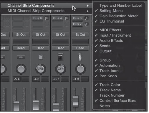
![]() Channel Strip Components: This submenu, shown in Figure 11.7 gives you control over exactly what components of your channel strip are shown in the Mixer. In the descriptions of the options in this submenu, any option that deals with an audio channel strip also applies to aux, bus, input, and output channel strips. The Channel Strip Components submenu options are as follows:
Channel Strip Components: This submenu, shown in Figure 11.7 gives you control over exactly what components of your channel strip are shown in the Mixer. In the descriptions of the options in this submenu, any option that deals with an audio channel strip also applies to aux, bus, input, and output channel strips. The Channel Strip Components submenu options are as follows:
![]() Type and Number Label: If this option is selected, the Mixer displays the channel strip type and number at the top of your channel strips.
Type and Number Label: If this option is selected, the Mixer displays the channel strip type and number at the top of your channel strips.
![]() Setting Menu: If this option is selected, the Mixer displays the Setting menu near the top of each audio/software instrument channel strip in the Mixer.
Setting Menu: If this option is selected, the Mixer displays the Setting menu near the top of each audio/software instrument channel strip in the Mixer.
![]() Gain Reduction Meter: If this option is selected, the Mixer displays Gain Reduction meters in each audio/software instrument channel strip.
Gain Reduction Meter: If this option is selected, the Mixer displays Gain Reduction meters in each audio/software instrument channel strip.
![]() EQ Thumbnails: If this option is selected, the Mixer displays the channel EQ thumbnail of each audio/software instrument channel strip.
EQ Thumbnails: If this option is selected, the Mixer displays the channel EQ thumbnail of each audio/software instrument channel strip.
![]() MIDI Effects: If this option is selected, the Mixer displays the MIDI FX of each software instrument channel strip.
MIDI Effects: If this option is selected, the Mixer displays the MIDI FX of each software instrument channel strip.
![]() Input/Instrument: If this option is selected, the Mixer displays the input/instrument of each audio/software instrument channel strip, respectively. Be aware that the left side of the Input field for any audio, aux, or output channel strip contains the Format button for that channel strip, which lets you change the format of the channel strip—mono, stereo, or surround. Hiding the Input/Instrument slots also hides the Format buttons.
Input/Instrument: If this option is selected, the Mixer displays the input/instrument of each audio/software instrument channel strip, respectively. Be aware that the left side of the Input field for any audio, aux, or output channel strip contains the Format button for that channel strip, which lets you change the format of the channel strip—mono, stereo, or surround. Hiding the Input/Instrument slots also hides the Format buttons.
Figure 11.7 The Channel Strip Components submenu.
© Apple Inc.
![]() Audio FX: If this option is selected, the Mixer displays the Audio FX of each audio/software instrument channel strip.
Audio FX: If this option is selected, the Mixer displays the Audio FX of each audio/software instrument channel strip.
![]() Sends: If this option is selected, the Mixer displays the sends of each audio channel strip.
Sends: If this option is selected, the Mixer displays the sends of each audio channel strip.
![]() Output: If this option is selected, the Mixer displays the output of each audio/software instrument channel strip.
Output: If this option is selected, the Mixer displays the output of each audio/software instrument channel strip.
![]() Group: If this option is selected, the Mixer displays the group of each channel strip.
Group: If this option is selected, the Mixer displays the group of each channel strip.
![]() Automation: If this option is selected, the Mixer displays the automation mode of each channel strip.
Automation: If this option is selected, the Mixer displays the automation mode of each channel strip.
![]() Track Icon: If this option is selected, the Mixer displays the track icon of each channel strip.
Track Icon: If this option is selected, the Mixer displays the track icon of each channel strip.
![]() Pan Knob: If this option is selected, the Mixer displays the Pan knob of each channel strip.
Pan Knob: If this option is selected, the Mixer displays the Pan knob of each channel strip.
![]() Track Color: If this option is selected, the Mixer displays the track colors for each channel strip.
Track Color: If this option is selected, the Mixer displays the track colors for each channel strip.
![]() Track Name: If this option is selected, the Mixer displays the track name of each channel strip.
Track Name: If this option is selected, the Mixer displays the track name of each channel strip.
![]() Track Number: If this option is selected, the Mixer displays the track number of each channel strip.
Track Number: If this option is selected, the Mixer displays the track number of each channel strip.
![]() Control Surface Bars: If this option is selected, the Mixer displays which channel strips are being controlled by your control surface.
Control Surface Bars: If this option is selected, the Mixer displays which channel strips are being controlled by your control surface.
![]() Notes: If this option is selected, the Mixer displays a Track Notes field under each channel strip. You can double-click on a Track Notes field to create or edit a note; those changes will be reflected in the parent track’s notes.
Notes: If this option is selected, the Mixer displays a Track Notes field under each channel strip. You can double-click on a Track Notes field to create or edit a note; those changes will be reflected in the parent track’s notes.
![]() MIDI Channel Strip Components: This submenu allows you to select or deselect individual components in the MIDI track. You can toggle the Instrument Name, Program, Bank, and Assign 1–5 controls for MIDI track strips by selecting or deselecting the relevant components.
MIDI Channel Strip Components: This submenu allows you to select or deselect individual components in the MIDI track. You can toggle the Instrument Name, Program, Bank, and Assign 1–5 controls for MIDI track strips by selecting or deselecting the relevant components.
Mixer Buttons
The Mixer has a number of buttons alongside the local menus. Figure 11.8 shows the Mixer buttons.
Figure 11.8 The Mixer buttons.
© Apple Inc.
The Mixer buttons, from left to right, are as follows:
![]() Hierarchy: Clicking the Hierarchy button, found at the left end of Figure 11.8, moves you up a level in your project’s hierarchy when working with folder tracks.
Hierarchy: Clicking the Hierarchy button, found at the left end of Figure 11.8, moves you up a level in your project’s hierarchy when working with folder tracks.
![]() Mixer View buttons: The Mixer View buttons allow you three different Mixer display options. You can also use the Cycle through Mixer Views key command, Shift+X. The buttons are as follows:
Mixer View buttons: The Mixer View buttons allow you three different Mixer display options. You can also use the Cycle through Mixer Views key command, Shift+X. The buttons are as follows:
![]() Single: This button displays the selected Tracks area track’s channel strip, as well as the signal flow of the selected track.
Single: This button displays the selected Tracks area track’s channel strip, as well as the signal flow of the selected track.
![]() Tracks: This button displays the channel strips of all Tracks area tracks. If you have selected the Add Signal Flow Channel Strips option, then all the other channel strips that the Tracks area tracks used will also be displayed.
Tracks: This button displays the channel strips of all Tracks area tracks. If you have selected the Add Signal Flow Channel Strips option, then all the other channel strips that the Tracks area tracks used will also be displayed.
![]() All: This button displays all the channel strips in your project.
All: This button displays all the channel strips in your project.
![]() Mixer Filter buttons: The Mixer Filter buttons allow you to toggle the display of specific channel strip types. You can toggle audio, software instrument (Inst.), aux, bus, input, output, master, and MIDI channel strips independently using these buttons. If you think you’ll use these filters often, remember to assign them their own key commands.
Mixer Filter buttons: The Mixer Filter buttons allow you to toggle the display of specific channel strip types. You can toggle audio, software instrument (Inst.), aux, bus, input, output, master, and MIDI channel strips independently using these buttons. If you think you’ll use these filters often, remember to assign them their own key commands.
![]() Channel Strip Size buttons: The Channel Strip Size buttons, shown at the right end of Figure 11.8, offer two channel strip sizes: Narrow (left button) and Wide (right button). Narrow channel strips offer the ability to fit more channel strips onscreen. Wide channel strips make it much easier to read things like audio FX names, track names, and track notes.
Channel Strip Size buttons: The Channel Strip Size buttons, shown at the right end of Figure 11.8, offer two channel strip sizes: Narrow (left button) and Wide (right button). Narrow channel strips offer the ability to fit more channel strips onscreen. Wide channel strips make it much easier to read things like audio FX names, track names, and track notes.
Recording Audio from the Mixer
NOTE: Throughout the rest of this chapter, everything discussed applies to either the Mixer or the Mixer layer.
You may choose to set up your audio recordings directly from the Mixer. This process consists of two steps.
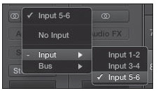
The first step is to select the physical input(s) on your audio interface that you want to use from the Input box of your channel strip. When you click and hold the box, a menu of all available inputs will appear (see Figure 11.9). From this menu, select the input you want to use.
Figure 11.9 From the Input menu, choose the hardware input you want to use for this track.
© Apple Inc.
Next, click the R button at the bottom of the channel strip. The R button flashes red, as you can somewhat discern from Figure 11.10. This indicates that when you click Record on the Transport, the track will record audio.
Figure 11.10 When you click the R button at the bottom of an audio track channel strip, it flashes red to indicate that the channel is now armed for recording.

© Apple Inc.
Repeat the preceding two steps for each track on which you want to record audio, remembering that only one track per input can be armed at any given time. After that, just click the Record button on the Transport (via mouse, hardware controller, or key command) and record away!
Basic Mixing: Summing Volume and Panorama
The most basic mixing that you’ll want to do is simply to adjust the volume of one track in comparison to another and to place tracks at different points across the stereo field, or panorama. If this is all you’ll ever want to use the Logic’s Mixer for, then this section will tell you all you’ll ever need to do to mix in Logic.
Volume Summing
Because each individual track is usually recorded with an ear toward getting the best recording of that specific source material, you almost never will initially record your tracks at the perfect level in relation to each other. This is why, since the beginning of recorded music, engineers have brought the level of one track up in a mix, while perhaps bringing another track down. The result is creating the perfect balance among all the various sounds in the mix.
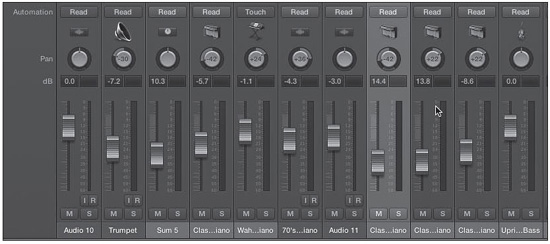
You adjust the volume of a channel by moving the onscreen Volume fader on its channel strip. If you are using a mouse, you’ll generally be able to adjust only one fader at a time, but if you have a hardware control surface, you may be able to adjust many faders at once. The numbers inside the fader represent either how many decibels you have added or subtracted from the initial volume of the track or the current MIDI volume, from 0 to 127. Figure 11.11 shows a Mixer in which the Volume faders have been adjusted to different levels to create a pleasing overall volume balance.
Figure 11.11 Mixing the volume of your tracks is as easy as sliding the Volume faders with your mouse or controller. You can also adjust the volume numerically.
© Apple Inc.
Option-clicking a Volume fader sets it to its null value, or the center point at which no adjustment is made. This is 0 dB for decibel faders and 100 dB for MIDI data faders. Clicking the number field in a fader allows you to enter a volume value numerically. Note that you will generally want to enter a negative value if you are entering a Volume setting manually.
Remember, if you have customized your Transport to include the Pre-Fader button, and you have pre-fader metering engaged, you’ll only see the input values of your track in the meter and not the impact of the Volume fader on the track’s level.
Panning
The other basic mixing technique you’ll find yourself wanting to do is placing tracks at different spots in the stereo panorama. This is known as panning. Panning can make tracks more distinct by placing them in a stereo location in which there is no other sound competing for the space. The technique can make mixes come alive by making the material sound as if it is coming from all over the stereo spectrum instead of having all sounds originating from the exact middle of the listening field. The Pan knob is above the Volume number fields, and you can adjust the pan value for any track by moving the knob to the right or left with either your mouse or a hardware control surface. Pan values range from −64 (full left) to +64 (full right), with 0 being the exact middle. Figure 11.12 shows a pair of tracks that have been panned differently to enhance the mix.
Figure 11.12 To adjust the pan of a track, rotate its Pan knob to the desired setting. You can also enter a pan value numerically.

© Apple Inc.
You can double-click the Pan knob to enter a pan value numerically, and Option-clicking on the Pan knob returns the pan value to the center. Keep in mind that you can automate these volume and pan settings as explained in the previous chapter so that your mix can be dynamic, with automatic changes happening exactly on cue.
The Direction Mixer Plug-In
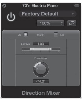
If you adjust the Pan knob on a stereo track, you aren’t really panning the signal between left and right, because the stereo signal already exists in both channels. Instead, you are adjusting the balance between the two channels. Sometimes this can work like panning, but sometimes it won’t. If you want more control over the track’s stereo panorama, check out Logic Pro’s built-in Direction Mixer effect, found in the Imaging submenu of an Audio FX slot. You can see the Direction Mixer interface in Figure 11.13.
Figure 11.13 The Direction Mixer effect.
© Apple Inc.
The Direction Mixer will allow you to not only adjust the balance of the signal, but also adjust the width of the stereo image and its location between the two channels. To apply this effect to a stereo signal, select LR as the input. You can then change the perceived width of the stereo signal with the Spread control and the perceived location of the signal with the Direction knob. You can also double-click in either parameter’s numerical display to enter a value directly.
This effect is also designed to decode mid-side audio recordings. To decode mid-side recordings with the Direction Mixer, select MS as your input. If you’re wondering what mid-side recording is, you probably shouldn’t select MS as your input, but the short answer is that mid-side configuration refers to a method for setting up two microphones, one with a figure-eight pattern and another with a cardioid pattern, to accurately record space and depth—but the resulting tracks need to be decoded in order to be used effectively. You can find a discussion of this and other multiple microphone techniques in Getting Great Sounds: The Microphone Book by Tom Lubin (Course Technology PTR, 2008).
The Binaural Panner
The Binaural Panner is a very powerful, very flexible stereo imaging tool. It adds spatial directional clues to your audio, giving your source a depth or presence in a mix that a typical pan control can’t achieve. To add a Binaural Panner to a mono or stereo channel strip, click on the channel strip’s Output box and select Binaural. The Pan knob will be replaced with the Binaural Pan control shown in Figure 11.14. Double-clicking on the Binaural Pan control opens the Binaural Panner window, shown in Figure 11.15.
Figure 11.14 Selecting the Binaural option in a channel strip’s Output box replaces the typical Pan knob with the Binaural Pan control.
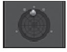
© Apple Inc.
Figure 11.15 The Binaural Panner window. Double-clicking the Binaural Pan control opens this plug-in–style window.
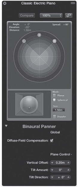
© Apple Inc.
You can drag the L or R dots to change the width of the stereo image. The middle circle determines the perceived direction and distance from which the sound will come. If you hold the Command key while dragging the blue dot, you can change the position of your audio while maintaining the same distance. Holding Option+Command while dragging the L or R dot locks the angle so you can tweak the distance.
The Binaural Panner has two modes: Planar and Spherical. Selecting Planar limits the motion of the controls to a plane. The Extended Parameters area of the Binaural Panner interface gives you three Planar mode controls: Vertical Offset, Tilt Amount, and Tilt Direction. These parameters give you control over orientation of the circular plane relative to the listener. Spherical mode, which you can see in Figure 11.15, allows you to simulate the positioning of sound in space.
The Size parameter defines the maximum size of the plane or sphere that the Binaural Panner will allow. The Doppler parameter simulates the pitch shifting that a listener experiences as his distance from a source changes, known as the Doppler effect. The Diffuse Field Compensation parameter in the Extended Parameters region delivers a more neutral sound to the listener.
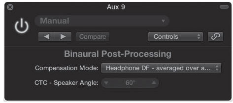
The Binaural Panner’s effect is most obvious when listening through headphones. That said, the power of the effect is such that you might be tempted to try it on a number of tracks through your studio monitors. To get the most out of the Binaural Panner, send all the channels strips you have set to Binaural through the same aux or output channel strip. In an Audio FX slot of the destination channel strip, instantiate the Binaural Post-Processing plug-in, found in the Imaging submenu and shown in Figure 11.16.
Figure 11.16 The Binaural Post-Processing plug-in.
© Apple Inc.
Set the Compensation mode to Speaker CTC–Cross Talk Cancellation. Then, set the CTC–Speaker Angle parameter to match the angle at which you have your studio monitors.
When using the Binaural Post-Processing plug-in, turn off the Diffuse Field parameter in all of your Binaural Panners. The Binaural Post-Processing plug-in will handle this operation for all of your Binaural Panner channels, freeing up CPU power.
Busing Tracks in Logic
When you play back your audio material in Logic, the most direct signal path your audio can follow for you to hear it is for the source audio channel strip to output its audio directly to the output channel strip connected to your hardware. Logic offers you more signal path options than this, however. As discussed in Chapter 7, “Working with Audio and Apple Loops,” these are basically parallel mixers that allow you to send a portion of your signal to another channel strip or to output a track into another Mixer channel strip for further grouping and processing instead of having to output that track directly to your hardware.
Using Aux Channel Strips
Aux channel strips are perhaps the most powerful and flexible channel strips in the Mixer. Clicking the Input box of an aux channel strip opens the Input menu for the aux channel strip, as shown in Figure 11.17. Notice that the aux channel strip can accept a hardware input, a bus, a ReWire output, or a multichannel output from a software instrument. Using an aux channel strip for multi-output software instruments and ReWire outputs was discussed in Chapter 9, “Working with Software Instruments.” The next two sections address using aux channel strips with live inputs and bus inputs.
Figure 11.17 When you click on the Input box of an aux channel strip, you access its Input menu.
© Apple Inc.
Using Aux Channel Strips with Live Inputs
Sometimes you may want to record some audio without effects but hear your source audio with some effects on it while recording. One way to do this is to set up an aux channel strip with a live input as its input source. This allows you to use an aux channel strip as a true auxiliary mixer in which one set of audio goes to your hard disk and another goes to the speakers or headphones.
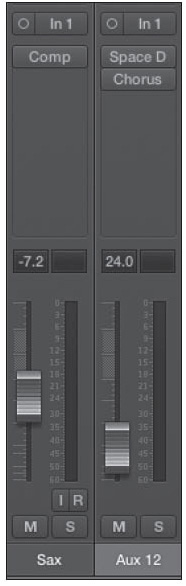
To use an aux channel strip this way, select one of your live inputs as the input for the aux channel strip. As soon as the source starts to play, you will hear the audio through the aux channel strip, as well as any audio track or input channel strip through which the audio is routed. Figure 11.18 shows an example of a setup with both an audio track and an aux channel strip using the same input for a source.
Figure 11.18 Here, an audio track will record using audio hardware interface input 1, while an aux channel is also getting its input from input 1. The aux channel is being used to add chorus and reverb effects.
© Apple Inc.
Such a setup is particularly useful when you have software monitoring turned off so that Logic is not monitoring the actual track doing the recording, and only the aux channel strip is playing back the source material during recording. This is also very useful if your vocalist likes to hear some effects while recording—for example, a bit of reverb or chorus—that are separate from whatever effects you’re actually tweaking on the vocal track’s audio channel strip. By setting up an aux track with effects, the vocalist will hear the performance through the aux with effects, but Logic will record the performance on the audio track without effects.
Using Aux Channel Strips with Buses
Often, you might want to assign a group of channels to a bus so you can use an aux channel strip to process all the tracks together and serve as a master fader for the group without using a Track Stack. In other words, say your song has 24 tracks of drums (a full drum kit, miked using 12 microphones), plus audio recorded directly through your audio interface without miking, plus software instruments. In addition to having individual controls for each track, you may want a master fader for a group of them, or to apply effects to all the channels once (such as putting them all through the same reverb to put the entire band in the same “room”). Logic allows you to set up an aux channel strip to serve this purpose by using its buses as a virtual patch bay between your source channels and the aux channel strip.
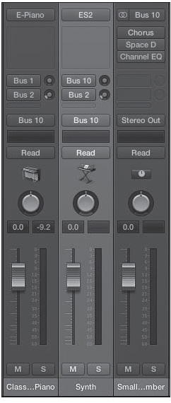
To do this, first you need to set the output setting of your source channels to a bus. Then set the input of your aux channel strip to the same bus to which you have set the output of the source channels. Figure 11.19 shows a simple setup in which two tracks are using an aux track as their bus destination.
Figure 11.19 The two channel strips on the left are software instrument tracks with their outputs set to bus 10. The channel strip on the right is an aux channel strip with its input set to bus 10. The aux channel strip can now be used as a master fader for the two source tracks, and effects can be added to both tracks via the aux.
© Apple Inc.
If you end up using aux channel strips as master group faders, as in Figure 11.19, I highly recommend you use aux channel strips as described here. Having the option to use sends on your master group fader is definitely worth it!
It’s also important to note that multiple aux channel strips can use the same bus as an input and that any aux can be bused to another aux. That means you can create some complex and creative routings, all automated in the main window, if you desire!
Using a Send to Feed an Aux Channel Strip
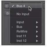
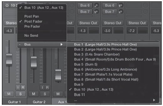
If you want to use a send to feed audio to an aux channel strip, simply click and hold a Send box, and a menu of all your available buses will appear. Select the bus you want and turn the Send knob to send to the bus the amount of audio you want. You then assign the destination aux channel strip’s input to the desired bus. Figure 11.20 shows the menu of a Send box with all the buses available for you to choose.
Figure 11.20 To send audio to an aux channel strip using a send, simply select the bus you want from the Send menu and then adjust the Send knob to send the desired amount of signal to the bus. Assign the input of an aux channel strip to the send’s bus.
© Apple Inc.
The Send menu includes Post Fader, Pre Fader, and Post Pan options. If you select Post Fader, Logic feeds your audio through the send after the Volume fader has adjusted its level. If you select Pre Fader, Logic feeds the audio through the send before the fader adjusts the volume of the channel. If you select Post Pan, Logic feeds your audio through the send after both the Volume fader and the Panorama knob have been adjusted. To turn off a send, you can click on its power button. Your Send box will stop glowing blue, indicating that it is turned off. It still retains the bus you chose for it, so clicking the power button again will reengage it.
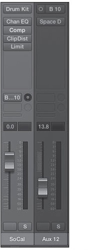
Busing audio to sends is especially useful when you want to use time- and modulation-based effects, such as delay, chorus, and reverb, to process your audio. Because you rarely want to process all your audio using these effects, you can insert the effect into the audio FX box of an aux channel strip and send a variable amount of your audio to that aux channel strip, adjusting the Send knob until you get just the right balance for your music. Figure 11.21 shows a Drummer track using a send to add a reverb that is inserted in an aux channel strip. Inserting effects in an Audio FX slot is discussed in more detail later in this chapter.
Figure 11.21 The channel strip on the left is for a Drummer track. The Drummer channel strip is using a send to feed the second channel strip, which is an aux channel strip in which Logic’s built-in Space Designer impulse response reverb is instantiated. By adjusting the Send knob on the Drummer channel strip, you can control how much reverb is added to the Drummer audio.
© Apple Inc.
Output Channel Strips
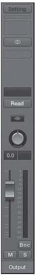
Output channel strips are the final destination for your audio. They connect directly to your hardware audio interface. You can have as many output channel strips as you have physical outputs on your audio hardware. Output channel strips have Audio FX slots for effects but no sends. This is because output channel strips portion out audio to hardware, not to additional processing channels within Logic. Output channel strips also don’t have Input boxes, as they are destinations for any audio that they receive. These objects include the Bounce button (labeled “Bnc” or “Bnce” depending on your channel strip width setting), which allows you to sum all the audio going to that output channel strip into a file on your hard disk.
Usually, a song has only a single output channel strip, which represents the hardware output that leads to your speaker system. Figure 11.22 shows an output channel strip for the main outputs to the audio hardware.
Figure 11.22 This output channel strip is hardwired to the main stereo outputs for the hardware interface used with this project.
© Apple Inc.
Sometimes you might want to use more than the main output channel strip. If you are mixing surround audio, for example, you may need 6–12 outputs, each sending to a discrete input on a hardware surround encoder. Perhaps you are not doing all your mixing in Logic, but sending tracks from Logic into a large studio mixing console. Or maybe you are sending out various tracks to various hardware processors and bringing the audio back into Logic for mixing. Whatever your use, you will use output channel strips to interface Logic with your audio hardware.
Using Effects
Mixing is not simply a matter of bringing together multiple source signals. Sometimes, you’ll want to process them as well. You can process audio in all sorts of ways. You can compress and distort audio; add EQ, delays, modulation, and reverb; link a track to external hardware for additional processing; and more. In traditional hardware studios, you need to cable an audio channel to a hardware effects processor to process a channel with effects. Just as software sequencers feature software mixers, they also feature software effects.
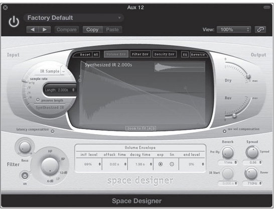
Effects in Logic generally have their own graphic editor that displays the parameters of the effect and often some visual representation of the current effect settings. This is called the Editor view. Figure 11.23 shows the Editor view of a Logic effect.
Figure 11.23 This is the graphic control window of Logic’s built-in reverb effect, Space Designer. Not only are the parameters given graphic controls, but the impulse response audio file and volume envelope are represented graphically, too.
© Apple Inc.
Notice that the plug-in window for effects has the same controls already discussed in Chapter 9 regarding software instruments. The menus and functions are identical in their operation, and the windows are fully resizable. You will most often want to work with your effects in Editor view because this is where you get the most pleasing user experience, as well as graphical feedback. Sometimes, however, if you know exactly what you want and you just want to adjust a parameter numerically, or if you are working with older effects without graphics, you might want to use Controls view. As Figure 11.24 shows, when an effect is in Controls view, the controls are nothing but sliders and value fields, menus, and checkboxes for the different parameters. You still have full control over your effect. Indeed, when you are looking to enter values very specifically, you might accomplish this most quickly in Controls view, but you do not get the aesthetic experience or graphical feedback that the Editor view offers. Also, with an effect as extensive as Space Designer, you’ll find yourself scrolling through a massive number of parameters looking for the one you want to tweak. This section explores using audio effects in Logic’s Mixer and offers some tips and suggestions for using effects in a mix.
Figure 11.24 This is the section of the Controls view of the Space Designer from Figure 11.23. It displays only a slider for each parameter.
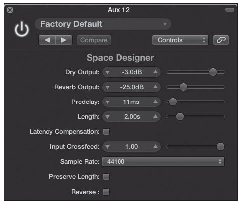
© Apple Inc.
Logic Effects
Apple ships Logic with a huge collection of professional-quality effects, which you can access from within Logic’s Mixer. You will often hear Logic’s effects referred to as plug-ins, since almost all other software effects are separate applications that are “plugged in” to a host digital audio sequencer, such as Logic. Logic’s effects, while accessed the same way as third-party plug-ins, are in fact built into the code of the application itself, just like Logic’s own softsynths. This is why you cannot access Logic’s effects in other applications that allow effects plug-ins, other than in Apple’s MainStage.
To access a Logic effect, click and hold on an Audio FX slot in a channel strip. A menu opens, listing the effects by type, such as Modulation, Dynamics, and Reverb. Once you select an effect type, a submenu opens, displaying the individual effects of the selected type. If the channel is mono, the menu that appears will offer you a mono effect, a mono -> stereo effect, or possibly both. If your channel is stereo, your default option is a stereo effect. You can force it to present mono effects by Option-clicking on the effect slot. Similarly, you can Option-click on a mono channel’s effects slot to force it to present only stereo effects. To instantiate a Logic effect, simply choose a Logic effect from the menus offered, as shown in Figure 11.25. After you select the effect you want and release the mouse button, the effect appears in the Audio FX slot in the channel strip, and the plug-in window opens in Editor view, ready to be configured.
Figure 11.25 To select a Logic effect, follow the menus and select the Logic effect you desire—in this case, Amp Designer.
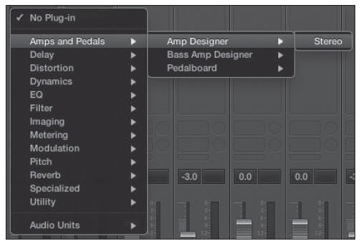
© Apple Inc.
Logic gives you a complete selection of all the effects you will need in modern music production, including all the standard dynamics-based effects (such as compression and limiting), time-based effects (such as delay and reverb), modulation effects (such as chorus and flange), and many unique offerings (such as Spectral Gate and Delay Designer). With 13 categories of built-in effects available, you’ll find most, if not all, of what you need for effects in Logic.
As with the Input field for softsynths, Logic’s Audio FX slots include power buttons to the left, a center area for accessing the plug-in window, and a menu access area to the right of the Audio FX field.
Logic Effects with Channel Strip Components
There is not enough space in this book to go over how to use each effect included with Logic Pro X. However, there are few plug-ins that interact with the channel strip differently than the others: the Channel EQ, the Linear Phase EQ, and the different Dynamics plug-ins that affect the Gain Reduction meter. These unique interactions are explained in the following sections.
Using the Channel and Linear EQ
As stated, Logic Pro X includes two professional-quality equalizer plug-ins: the Channel EQ and the Linear Phase EQ. Both are filters that can adjust the frequency response of your audio, and they look and operate identically. The main difference is that the Linear Phase EQ maintains the exact phase relationship of the frequencies of your audio material, which are altered at extremes using non-linear phase EQ algorithms. In other words, it does a better job of maintaining the integrity of your material the more intensely you apply equalization.
The price of this advanced linear phase algorithm is both increased CPU overhead and increased processing delay. Processing delay is discussed later in this chapter, in the section “Plug-In Delay and Logic’s Plug-In Delay Compensation” section. The point is, you’ll want to be judicious in your use of Linear Phase EQs.
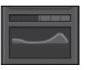
If you have the EQ Thumbnails parameter turned on in the Mixer or in an audio channel strip’s Inspector in the Mixer layer, the top of the channel strip has a rectangular box that displays a thumbnail representation of the current EQ curve, as in Figure 11.26. This EQ thumbnail box offers you easy access to the Channel EQ and Linear Phase EQ plug-ins and a visual reference of the current EQ curve. When the EQ thumbnail box is empty, it is just a plain gray slot like any other empty slot in a channel strip.
Figure 11.26 A channel strip’s EQ thumbnail box above the Inserts parameter. This box is where you can access your Channel EQ and see the current EQ curve.

© Apple Inc.
To activate the Channel EQ, you can simply double-click inside the thumbnail box. Logic opens a plug-in window in Editor view for the Channel EQ plug-in, places a thumbnail of the grid display of the new Channel EQ in the EQ thumbnail box, and instantiates the Channel EQ plug-in into the top-most available Audio FX slot. You can force the Channel EQ to the top-most slot by Option-double-clicking on the EQ thumbnail field.
You cannot click in the box to instantiate the Linear Phase EQ, but if you add a Linear Phase EQ effect on your own, it also will show its grid in the EQ thumbnail box. As you adjust the parameters in the Channel or Linear Phase EQ, this thumbnail box reflects the EQ curve that is created in the plug-in window. This offers you a quick visual reference as to how you have EQed that channel. If you need to make an adjustment, you can double-click the EQ thumbnail box to open the Channel or Linear Phase EQ (depending which you have instantiated).
If you have multiple Linear Phase or Channel EQ effects in one track, only the top-most EQ will have its grid showing in the EQ thumbnail box.
The Gain Reduction Meters
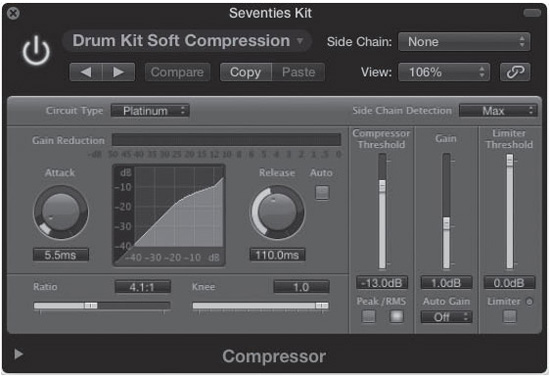
If you have chosen to view Gain Reduction meters, all audio and software instrument channel strips will feature a small Gain Reduction meter above the EQ thumbnail box. This allows you to monitor the amount of gain reduction performed by the first Compressor, Limiter, or Adaptive Limiter effect inserted in an Audio FX slot on a channel strip. Figure 11.27 shows a Gain Reduction meter at work.
Figure 11.27 The Gain Reduction meter lets you monitor the amount of gain reduction the first Compressor, Limiter, or Adaptive Limiter effect is performing on any track with one of these Dynamics plug-ins instantiated.
© Apple Inc.
Similar to the EQ Thumbnails area, if you double-click on an empty Gain Reduction meter, an instance of Compressor is opened by default, along with its plug-in window in Editor view. Option-double-clicking in the Gain Reduction meter slot forces the Compressor to the top effects slot. If you instantiate a Compressor, Limiter, or Adaptive Limiter effect on a channel without one of those Dynamics plug-ins already instantiated, the Gain Reduction meter for that channel strip will become active for the new Dynamics plug-in.
Effects Side Chains
Some effects, such as Logic’s Compressor, Expander, and AutoFilter, as well as some third-party plug-ins, have what is called a side-chain input. A side chain is an input to an effect or plug-in that allows another audio track to trigger that effect or plug-in. You can use side chains to configure an effect to activate only when a signal from the side-chain input is present. One example of this would be to have a compressor on a bass track triggered by a kick drum on another track, so that the bass is compressed only when the kick drum appearing at the side-chain input sounds to create a tighter feel for the rhythm. Side chains are also very useful for ducking (making a signal softer when another signal is present), for vocoder effects and instruments (where an audio channel is sent into the side chain of a vocoder software instrument to “play” the vocoder), and so on. The side-chain input looks like an additional menu on the plug-in window control bar, as shown in Figure 11.28.
Figure 11.28 The side-chain input can be seen on the Compressor effect in Logic as a new menu on the far right of the control bar.
© Apple Inc.
To select a track to use as the side-chain input, simply select an available audio source from the menu, as shown in Figure 11.29. The track you choose triggers the operation of the effect.
Figure 11.29 To use one of these available tracks as the side-chain trigger, select it from the menu.
© Apple Inc.
The more audio tracks, inputs, and buses you have active, the more potential side-chain input sources you’ll have. Not all plug-ins or effects have side-chain inputs, but for those that do, it opens a whole new creative way to use effects.
Using the Side-Chain Input to Rescue Lackluster Kick Drums: Producer, co-author of Logic 7 Ignite!, and Logic guru Don Gunn offers his expert method for how you can use the side-chain input feature to add “guts” to a kick drum performance that isn’t punchy enough:
If you find yourself mixing a song and the kick drum just isn’t providing the bottom end you’d like, there’s an easy way to create low-frequency content. This tip utilizes Logic’s software instruments as well as the side chain feature on the Noise Gate plug-in. With your kick drum track in the Mixer, assign an unused bus to one of the sends. Next, create a software instrument track and assign the track a software instrument of your choice for generating low tones. Any of the built-in Logic synthesizers work, but using a multi-oscillator synth, with one oscillator set to generate a sine wave, as well as a secondary sine sub-oscillator for additional fatness, works better. Now insert a Noise Gate plug-in on the Software Instrument track and assign the side-chain input to the bus that was assigned to the send on the kick drum track. If you play this track as it is currently set up, you will still only hear the original kick drum; for the instrument to produce sound, it needs a note that is affected by the incoming signal via the Noise Gate side chain. Create a note and make its length be the duration of the kick drum region that needs reinforcement. One benefit to this technique is that you can have the kick drum trigger a note that is in key with your song, helping to reinforce the notes being played by the bass part. At this point, when the song is played back, the kick drum will trigger the side chain on the Noise Gate to open, allowing the tone of the synthesizer to go to the output. Using the envelope controls in the Noise Gate (Attack, Hold, Release), you can make the tone of the synthesizer longer or shorter; give the note a short, clipped attack; or have the low-frequency material swell in behind the original kick drum. You can also adjust the sensitivity of the Noise Gate with the Threshold and Reduction parameters. Experimentation is the key, and while this Drum Replacement/Doubling function gives you one great tool for beefing up a kick drum, the side-chain method can produce results that other methods just can’t achieve!
Audio Units Effects
You may want to use an effect not included with Logic, or you may prefer to use a different version of an effect than the one Logic provides. To this end, all versions of Logic allow you to use third-party effects plug-ins as well as third-party software instruments. As discussed, these third-party applications literally “plug in” to Logic’s Mixer and offer extended processing functionality from within Logic. There are a number of different plug-in formats with which different sequencers are compatible. Logic Pro X is compatible with Apple’s native Audio Units (AU) format.
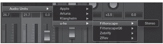
To access third-party effects, you follow the same basic procedure as you use with Logic effects. The difference is that instead of selecting Logic effects, you select Audio Units and then choose your effect from the list of manufacturers. Figure 11.30 shows a third-party Audio Units effect being selected.
Figure 11.30 To select a third-party Audio Units effect, you follow the same general procedure as when selecting a Logic effect, except that you follow the menu of Audio Units plug-ins.
© Apple Inc.
The Audio Units Manager
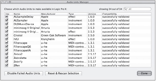
As you can imagine, there are hundreds of third-party Audio Units effects available, some of which come in bundles that are quite inexpensive. Remember when buying AU plug-ins to make sure they are 64-bit plug-ins. Although Logic has been a 64-bit app since 2009, many commercial plug-ins have not been ported to 64-bit. In spite of this, you may find that in no time flat your lists of available AUs will become huge! Thankfully, Logic Pro X includes an integrated way to manage your Audio Units plug-ins. This is called the Audio Units Manager (see Figure 11.31). To launch the Audio Units Manager, select Logic Pro X > Preferences > Audio Units Manager.
Figure 11.31 The Audio Units Manager. You can select and deselect the checkboxes to specify which AUs will be available in the plug-in menus in Logic Pro X.
© Apple Inc.
The Audio Units Manager displays each of your Audio Units plug-ins in a row, one after the other. The Audio Units Manager contains six columns:
![]() Use: Select this checkbox if you want a plug-in to appear in the plug-in menus within Logic. Deselect this checkbox if you do not.
Use: Select this checkbox if you want a plug-in to appear in the plug-in menus within Logic. Deselect this checkbox if you do not.
![]() Name: This is the name of the Audio Units plug-in.
Name: This is the name of the Audio Units plug-in.
![]() Manufacturer: This is the name of the developer of the Audio Units plug-in.
Manufacturer: This is the name of the developer of the Audio Units plug-in.
![]() Type: This column tells what kind of plug-in each Audio Units plug-in is, such as effect, instrument, or MIDI-controlled effect.
Type: This column tells what kind of plug-in each Audio Units plug-in is, such as effect, instrument, or MIDI-controlled effect.
![]() Version: This column contains the version number of each Audio Units plug-in.
Version: This column contains the version number of each Audio Units plug-in.
![]() Compatibility: This column tells you whether the plug-in passed, failed, or crashed Apple Computer’s Audio Units Validation scan. Audio Units Validation is covered in the next section.
Compatibility: This column tells you whether the plug-in passed, failed, or crashed Apple Computer’s Audio Units Validation scan. Audio Units Validation is covered in the next section.
Using the Logic Audio Units Manager couldn’t be easier. If you don’t need an AU to appear in the plug-in menus within Logic, deselect the checkbox in the Use column. If you want to reactivate a plug-in that you deactivated, reselect its checkbox. When you’re finished, simply click the Done button at the bottom-right of the Audio Units Manager to close it.
The Audio Units Manager includes one additional, vital function besides Audio Units management. It also scans your Audio Units for compatibility with the Audio Units format and deactivates them for you if they fail or crash validation. This is explained in more detail next.
INITIAL AU SCAN
Apple wants Logic Pro X to be the most stable audio application possible. To ensure this, Apple takes pains to test the application rigorously before release. Unfortunately, third-party plug-ins are not within Apple’s power to test and debug. In the past, this has meant that plug-ins that often didn’t “play nice” with Logic could crash Logic, or in some cases, bring down your entire computer! To help mitigate this, Apple created a free diagnostic application for developers: the AU Validation Tool. This tool basically runs a number of diagnostic tests on an Audio Units plug-in in an attempt to ensure that it properly complies with the Audio Units format specifications and will not destabilize the host application.
When you first run Logic Pro X and every time you install a new Audio Units plug-in, Logic will scan the plug-in with the AU Validation Tool to test the plug-in for compatibility and stability. Normally, all you will see is a progress bar indicating that scanning is taking place, and that’s it. When Logic Pro opens, your new plug-in will typically be available in the appropriate menus.
Sometimes, however, you may find that a plug-in you installed does not appear in the menu. This most likely means that the plug-in failed validation. At this point, if you open the Audio Units Manager, you will find that your plug-in is not checked along with the message that it failed or crashed validation.
If you believe that the scan results were somehow incorrect, you have the option to click the Reset & Rescan Selection button. The Audio Units Manager will then rescan just the selected AU plug-in and present you with the results. If the plug-in still fails validation, I highly recommend that you contact the developer with this information. If you want to be extra helpful, you can even copy and paste the rescan results into an email and send it directly to the developer, saving them from having to run it themselves. It is up to the developer to release an update that complies with the Audio Units specifications. When they do, Logic will scan the updated plug-in, it will pass the scan, and your plug-in will work properly!
ACTIVATING INCOMPATIBLE AU PLUG-INS
What if you absolutely, desperately need to use an incompatible Audio Units plug-in in Logic—say, to finish a project on deadline? For these emergency situations, you can, if you want to, activate an incompatible plug-in in Logic. To do so, simply select its Use checkbox, just like a compatible plug-in. Plug-ins that you activate this way are filtered into their own special menu for incompatible plug-ins in the Audio FX and instrument slot menus.
I highly recommend against activating incompatible plug-ins unless you absolutely have no choice. The whole purpose of scanning Audio Units plug-ins is to try to ensure that Logic Pro will not be destabilized by an errant plug-in. If you activate a plug-in that crashes or fails validation, you defeat the whole purpose of the scan! This is truly a feature of last resort. Waiting for an update that successfully passes AU validation is always the best policy.
Using Audio FX
Audio effects are really simple to use, as you have seen. Simply select an effect for an Audio FX slot, and you’re ready to use it! Bypassing an insert effect is just as easy. To bypass an effect, click the power button in its Audio FX slot. The effect will stop glowing, indicating the effect is bypassed.
Saving or Loading Channel Strip Settings
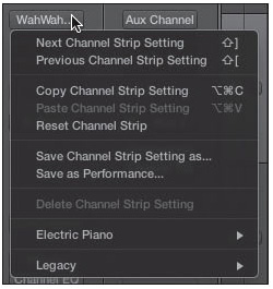
In addition to being able to save and load individual effects settings, Logic gives you the option to save and recall entire configurations of channel strip inserts—including software instruments. If you click and hold the Setting box on a channel strip, a menu like the one is Figure 11.32 will appear, offering you options to save, load, and navigate channel strip settings.
Figure 11.32 Clicking the Setting box on a channel strip opens the Setting menu, where you can manage and navigate channel strip settings.
© Apple Inc.
The functions of the commands in the Setting menu are as follows:
![]() Next Channel Strip Setting: This command changes the configuration of the channel strip to the next channel strip setting. The key command is Shift+] (right bracket).
Next Channel Strip Setting: This command changes the configuration of the channel strip to the next channel strip setting. The key command is Shift+] (right bracket).
![]() Previous Channel Strip Setting: This command changes the configuration of the channel strip to the previous channel strip setting. The key command is Shift+[ (left bracket).
Previous Channel Strip Setting: This command changes the configuration of the channel strip to the previous channel strip setting. The key command is Shift+[ (left bracket).
![]() Copy Channel Strip Setting: This command allows you to copy an entire channel strip configuration to the Clipboard so you can paste it into another channel strip. The key command is Option+Command+C.
Copy Channel Strip Setting: This command allows you to copy an entire channel strip configuration to the Clipboard so you can paste it into another channel strip. The key command is Option+Command+C.
![]() Paste Channel Strip Setting: This command allows you to paste an entire channel strip setting from the Clipboard into a channel strip. The key command is Option+Command+V.
Paste Channel Strip Setting: This command allows you to paste an entire channel strip setting from the Clipboard into a channel strip. The key command is Option+Command+V.
![]() Reset Channel Strip: This command allows you to quickly remove all plug-ins and send routings from a channel strip.
Reset Channel Strip: This command allows you to quickly remove all plug-ins and send routings from a channel strip.
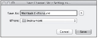
![]() Save Channel Strip Setting As: This command allows you to save your own channel strip settings. When you save a channel strip setting, a Save dialog box like the one in Figure 11.33 opens.
Save Channel Strip Setting As: This command allows you to save your own channel strip settings. When you save a channel strip setting, a Save dialog box like the one in Figure 11.33 opens.
Figure 11.33 The Save Channel Strip Setting As dialog box.
© Apple Inc.
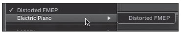
TIP: It is helpful to create a new folder structure inside the default folder to organize your channel strip settings. Otherwise, all your channel strip settings will show up as a list in the Setting menu. Figure 11.34 shows a Setting menu with two instances of the same software instrument channel strip setting—one saved in the default Instrument folder and another saved in a folder created inside the Instrument folder.
Figure 11.34 This Setting menu shows one channel strip setting directly in the menu and another that has been nested in a submenu. Creating subfolders in the Save Channel Strip Setting As dialog box allows you to create submenus in the Setting menu, which will help you keep your channel strip settings organized.
© Apple Inc.
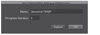
![]() Save as Performance: This command allows you to save your channel strip setting as a performance, which enables you to recall the channel strip setting via a MIDI program change message. Selecting this command opens the Save Channel Strip Setting as Performance dialog box shown in Figure 11.35. Simply name your performance, enter the program change number you wish to use in the Program Number field (0–127), and click OK. You can now use a program change message with the number you selected to recall your channel strip setting. Be aware that the program change message must be transmitted on MIDI channel 1.
Save as Performance: This command allows you to save your channel strip setting as a performance, which enables you to recall the channel strip setting via a MIDI program change message. Selecting this command opens the Save Channel Strip Setting as Performance dialog box shown in Figure 11.35. Simply name your performance, enter the program change number you wish to use in the Program Number field (0–127), and click OK. You can now use a program change message with the number you selected to recall your channel strip setting. Be aware that the program change message must be transmitted on MIDI channel 1.
Figure 11.35 The Save Channel Strip Setting as Performance dialog box. Saving your channel strip setting as a performance gives you the ability to recall your channel strip setting via a MIDI program change message.
© Apple Inc.
![]() Delete Channel Strip Setting: This command allows you to delete the current channel strip setting.
Delete Channel Strip Setting: This command allows you to delete the current channel strip setting.
Beneath the Setting menu commands you’ll find submenus full of channel strip settings. Channel strip setting files include all the insert effects instantiated on the channel strip (complete with their effects settings as they were saved). If you are on a software instrument channel strip, it will include the software instrument as well. The beauty of channel strip settings is that you can save configurations of channel strip inserts that you use regularly—for example, if you have a particular set of plug-ins you like to use to process vocals. You can save them as a channel strip setting and have quick access to your favorite configuration at all times. Logic Pro comes with a very wide variety of factory preset channel settings for you to explore as well. Give them a listen!
NOTE: With all the different settings and patches available, it may be a bit confusing keeping them all straight. Think of them like measuring cups, where one nests inside another. When you load a plug-in, you can access a setting or save a setting for that plug-in in its own Settings menu. Your saved settings for that plug-in are available in any Logic project. You can have multiple plug-ins on the same channel strip, working in concert, that you can save as a channel strip setting for use in any project. Finally, you have patches—multiple channel strips and Track Stacks, with different channel strips featuring unique combinations of plug-in settings, channel strip settings, and bus routings to auxes full of their own settings. Your patches are also available in any project. Logic gives you the ability to work from the simplest individual plug-in to massive routings, all portable across your projects. The more you get used to using these varying and expanding approaches to saving and recalling individual plug-in presets, preset groups of plug-ins on a channel strip, and entire preset collections of channel strips, their plug-ins, and their routings, the more you will get out of Logic!
Using Send Effects
Using a send to add effects to a track is a bit more complicated than using audio effects on your source channel strip. This is because sends don’t directly connect to effects; instead, they connect through buses to aux channel strips. To use a send to add effects, you assign a send to a bus, then add the effect you desire in an Audio FX slot of the aux channel whose input is assigned to that bus. You control how much of your audio signal is bused to the aux via the Send knob.
Plug-In Delay and Logic’s Plug-In Delay Compensation
Most effects do their processing nearly instantly. Some, however, do not. They may involve highly complex mathematical processes, like convolution reverbs, such as with Logic’s Space Designer. Or they might have a “look ahead” feature, by which the effect increases its accuracy by scanning the recorded audio—literally “looking ahead” before it processes it, which requires that the effect hang on to the audio signal for a while instead of instantly processing it. Some Audio Units plug-ins run on FireWire or on PCI Express or ExpressCard DSP devices, such as the UAD-2 cards; it takes time to get the audio out to these devices.
The point is, some devices and plug-ins introduce a delay into your signal path. This can be a real problem. For example, if you have two tracks that are both in sync with each other and set to play at bar 1.0.0.0, but one track has plug-ins that introduce 2,000 samples of delay, that track will play late and out of sync. If you are not careful, plug-in delay can really ruin your song.
Luckily, Logic tries to make things a bit easier for people. There is a Compensation menu in the General tab of the Audio Preferences window for plug-in delay compensation, as shown in Figure 11.36.
Figure 11.36 The Compensation menu in the General tab of the Audio Preferences window. You can determine how plug-in delay compensation will work in your project from this menu.

© Apple Inc.
There are three options in the Compensation menu:
![]() Off: This means there will be no plug-in delay compensation. If you’re not using any plug-ins that need compensation, then this is the preferred setting.
Off: This means there will be no plug-in delay compensation. If you’re not using any plug-ins that need compensation, then this is the preferred setting.
![]() Audio and Software Instrument Tracks: Selecting this will automatically adjust any of your audio and software instrument tracks to be in sync with any other audio and software instrument tracks that have delay-causing effects on them.
Audio and Software Instrument Tracks: Selecting this will automatically adjust any of your audio and software instrument tracks to be in sync with any other audio and software instrument tracks that have delay-causing effects on them.
![]() All: Selecting this allows you to compensate for delay-inducing plug-ins across your entire project, including outputs and auxes. All is the default plug-in delay compensation mode of Logic Pro X.
All: Selecting this allows you to compensate for delay-inducing plug-ins across your entire project, including outputs and auxes. All is the default plug-in delay compensation mode of Logic Pro X.
Keep in mind that plug-in delay compensation works only during playback, not during recording. If you have no choice but to record with plug-ins that cause some processing delay, be sure to use Low Latency mode, as explained in Chapter 5, “Transport Controls and Recording.”
Final Notes on Using Effects
Using effects is arguably one of the most dramatic ways to alter an audio mix. Sometimes, the effects become instruments themselves, and their processing is an integral part of the music. But as with all things, it’s very easy to get carried away both musically and computationally.
Keep in mind that your computer has only a finite amount of CPU power. If you try to process every track to death in a large project, you’ll most likely overtax your computer to the point that your project no longer plays back. And if you really overdo it, you might so overextend your resources that your project won’t play unless you engage Freeze for every track! Also, don’t forget to use Bounce in Place whenever possible. Once a track is finished, there’s no point in having it steal more CPU cycles than are absolutely necessary.
If you are using a fair number of software instruments and effects in a given song, keep a close watch on your system performance to make sure your computer is up to your demands. You can get a gauge of Logic’s audio CPU and hard disk usage from the load meters in the Transport, which you can open in their own windows by double-clicking on them. This is another advantage to using some effects on aux channel strips and having tracks access them via sends. You can have more than one track access the same aux, thereby saving you from having to instantiate that same effect on more than one track.
Beware of the pitfall of EQing and effecting one track until it is perfect when played by itself, but muddies everything up when placed in the context of the mix. That infinite delay line that you love so much might just start getting jumbled when you bring in 24 more tracks and it’s been repeating for 90 seconds! Even as you work on perfecting individual tracks, always try to keep a holistic view of what you want the completed project to sound like. Logic Pro’s signal analysis effects—Correlation Meter, MultiMeter, and Level Meter—can help you get a better picture of your material, where there is too much signal energy, and where you might want to adjust your mix to sound more open or less overloaded. The saying “less is more” definitely applies to mixing!
Lastly, remember that there are no hard and fast rules as to how to add effects to a mix. Listen to effects on a lot of your favorite CDs, read magazines and books that discuss effects placement and usage in detail (Cengage Learning sells a fair number of books on mixing; go to cengage.com to check them out), and, of course, don’t forget to experiment on your own!
Muting Channels
From Chapter 6, “The Logic Pro Main Window,” you’re already familiar with the Mute button on each track in the main window. That button mutes or unmutes either a single track or all tracks routed to a single channel strip. To mute the dependent tracks of a channel strip, you must turn those tracks off using the power buttons in their track headers. Each channel strip also has a Mute button at its bottom, as shown in Figure 11.37. Clicking this button mutes or unmutes the channel in question. Muting a channel strip also mutes the Mixer output of all dependent tracks of the muted channel strip.
Figure 11.37 The button with the M is the Mute button for this channel strip. If mute is engaged, the button on the channel strip glows light blue.

© Apple Inc.
Soloing Channels
Each channel strip except for output channel strips has a Solo button like the one in Figure 11.38. When the Solo button is engaged, all other channel strips, other than dependent aux channel strips and output channel strips, are silenced unless they have their Solo buttons engaged. When one or more tracks are soloed, the M in the Mute buttons of the non-soloed tracks flash.
Figure 11.38 When the Solo button of a channel strip is activated, all non-soloed channel strips are silenced except for output and aux channel strips. The Solo button will glow yellow when activated.

© Apple Inc.
Solo does not silence output channel strips because output channel strips are necessary for the soloed tracks to be heard. Also, soloing channels is strictly an audio function; MIDI tracks are not muted unless their audio is routed into Logic. Additionally, soloing a channel strip that is bused to an aux channel strip does not mute the dependent aux, as you can see in Figure 11.39.
Figure 11.39 Soloing a channel strip that is bused to an aux channel strip does not mute the dependent aux. Here you can see a signal in the level meters of the soloed channel strip, its dependent aux channel strip, and the output channel strip.
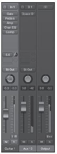
© Apple Inc.
If you are using an aux as the destination of a send and do not wish to hear the processing you are applying on the aux while soloing a parent channel strip, you can mute the aux.
Soloing an aux channel strip passes all audio routed to that aux through to its output. If the parent channel strips are assigned to an output channel strip, then their output signal is muted. This can be very handy for dialing in the settings on insert effects with precision. In Figure 11.40, aux 12 is using bus 18 as an input. The three channel strips to the left of aux 12 are sending signal to aux 12 through bus 18. Notice that while there is no signal registering in any of the software instrument’s level meters, aux 12 is sending signal to the output channel strip.
Figure 11.40 When you solo an aux channel strip that is the destination of a send, the dry signal of its parent channel strips is muted. The aux still receives signal from its parent channel strips through its input bus and sends its soloed signal to the output channel strip.
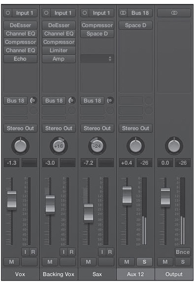
© Apple Inc.
It’s important to note that the Solo button in the Mixer interacts with the Solo buttons in the main window in a similar way to the Mute buttons. Also, Option-clicking a currently unsoloed channel strip will solo that particular channel strip and turn solo off on any currently soloed channel.
Because of the many different ways that soloed channels can interact, you may want to solo safe certain channels in your project. What does solo safe mean, you ask? Good question….
Solo Safe Mode
If you want to make sure that no matter which tracks are soloed, you never silence certain tracks, effects, buses, and so on, you can make them solo safe to exempt them from being silenced. Control-clicking the Solo button turns on Solo Safe mode for a given channel strip. You can tell whether a track is in Solo Safe mode because its Solo button will have a line through it, as in Figure 11.41. Control-clicking the Solo button a second time disengages Solo Safe mode.
Figure 11.41 A red line through a deactivated Solo button on a channel strip indicates the channel strip is in Solo Safe mode.

© Apple Inc.
Mixer Groups
Sometimes you may want to link some properties of different channel strips. For example, you might want the volume, solo, and mute functions of all your drum tracks to change together as a group, or you might want to link the Pan control of a group of tracks that are all panned to the same location. The Group function allows you to do this and more. You can use the Group function not only to group Mixer operations, but also to link Tracks area functionality for group editing.
The Group slot is the dark-gray display window directly below the Output field in each channel strip, as shown in Figure 11.42. This is where you can select and create groups. You can create as many as 32 groups, and channels can belong to multiple groups.
Figure 11.42 Directly under the Output menu and above the Automation Mode menu is the Group slot. In this figure, the channel strip is assigned to group 1.

© Apple Inc.
Assigning Channels to Groups
To assign a channel to a group, click in the Group slot on the channel strip. A menu will appear with the numbers (and names, if assigned) of any current Mixer groups, as well as the option to create a new group, and to open the Group Settings window. If you are creating your first group in a project, select Group 1: (new). After you have created more groups by selecting Group x: (new), where x is any number from 2–32, you can assign a channel strip to any available group. The number of the group you have selected appears in the Group display of your channel strip. Figure 11.43 shows the Group menu with group 1 already created and group 2 ready to be created.
Figure 11.43 In the Group menu, you can choose the number of the group to which you want to assign your channel, create a new group, or open the Group Settings window.
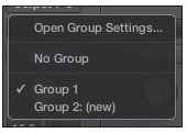
© Apple Inc.
You can assign a channel to more than one group by holding down Shift while selecting groups in the menu. If you Option-click in the Group slot, the last group selection is applied to the current channel strip. This is especially handy for quickly assigning a large number of channel strips to the same group.
Group Settings
You can access the Group Settings window in a few ways. If you assign a group to a channel, the Inspector in the main window will add a Groups Inspector. You can drag the Groups Inspector header to open a separate but identical Group Settings window. You can also select the Open Group Settings option in the Group menu or use the key command Option+Shift+G. Figure 11.44 shows the Groups Inspector in the main window Inspector.
Figure 11.44 The groups Inspector is identical to the Group Settings window.
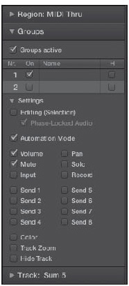
© Apple Inc.
The Group Settings window contains a list of options, each with a checkbox (except for the Name option). If you select the checkbox next to an option, that option will be set to the group. So, if you adjust the control or do any editing or automation in one channel in the group, that action affects all channels in the group. The following list describes the various options.
![]() Groups Active: This checkbox allows you to turn all groups on or off globally.
Groups Active: This checkbox allows you to turn all groups on or off globally.
![]() Groups list: This list lets you control the following group options.
Groups list: This list lets you control the following group options.
![]() Nr: This column displays the available group numbers.
Nr: This column displays the available group numbers.
![]() On: To turn on an available group, select its checkbox in this column.
On: To turn on an available group, select its checkbox in this column.
![]() Name: Double-click in the Name field to access a text box in which you can type a name for your group. The first seven or eight letters of the group’s name will appear in the Group display in the channel strip, along with the group number.
Name: Double-click in the Name field to access a text box in which you can type a name for your group. The first seven or eight letters of the group’s name will appear in the Group display in the channel strip, along with the group number.
![]() H: Selecting a group’s H checkbox hides that group. If one or more tracks in the group are already hidden, the checkbox will display a dash in it, but you still have the ability to hide all the group’s tracks by clicking on the checkbox. This is different from using an individual track’s Hide function, because you have to access the Group Settings window to toggle a group’s Hide status.
H: Selecting a group’s H checkbox hides that group. If one or more tracks in the group are already hidden, the checkbox will display a dash in it, but you still have the ability to hide all the group’s tracks by clicking on the checkbox. This is different from using an individual track’s Hide function, because you have to access the Group Settings window to toggle a group’s Hide status.
![]() Settings area: The Settings area lets you configure what functions affect your group as a whole. The group settings are as follows:
Settings area: The Settings area lets you configure what functions affect your group as a whole. The group settings are as follows:
![]() Editing (Selection): With this option selected, if you select a region on one track in the group in the Tracks area, every track in the group will have any regions at the same relative time in the song selected.
Editing (Selection): With this option selected, if you select a region on one track in the group in the Tracks area, every track in the group will have any regions at the same relative time in the song selected.
![]() Phase-Locked Audio: With this option selected, a group that has Editing (Selection) enabled will remain phase-locked if you quantize its audio. If you are Flex editing grouped tracks, this option must be enabled.
Phase-Locked Audio: With this option selected, a group that has Editing (Selection) enabled will remain phase-locked if you quantize its audio. If you are Flex editing grouped tracks, this option must be enabled.
![]() Automation Mode: Changing the Automation mode of one member of the group changes all of them.
Automation Mode: Changing the Automation mode of one member of the group changes all of them.
![]() Volume: Changing the Volume fader of one channel strip in the group changes all of them. Note that these are relative changes, so if two channels in the group are at different volumes, Logic raises or lowers both volumes by the amount of the change to the group, but they retain their relative difference in volume.
Volume: Changing the Volume fader of one channel strip in the group changes all of them. Note that these are relative changes, so if two channels in the group are at different volumes, Logic raises or lowers both volumes by the amount of the change to the group, but they retain their relative difference in volume.
![]() Mute: If one channel in the group is muted/unmuted, every channel in the group is muted/unmuted.
Mute: If one channel in the group is muted/unmuted, every channel in the group is muted/unmuted.
![]() Input: With Input selected, all tracks in the group will use the same Input setting.
Input: With Input selected, all tracks in the group will use the same Input setting.
![]() Pan: Logic adjusts the pan of every channel in the group if you adjust one channel’s pan. As with the Volume option, all channels retain their relative differences from each other.
Pan: Logic adjusts the pan of every channel in the group if you adjust one channel’s pan. As with the Volume option, all channels retain their relative differences from each other.
![]() Solo: If one channel in the group is soloed/unsoloed, every channel in the group is soloed/unsoloed.
Solo: If one channel in the group is soloed/unsoloed, every channel in the group is soloed/unsoloed.
![]() Record: Record-enabling/disabling one channel in the group record-enables/disables all the channels in the group.
Record: Record-enabling/disabling one channel in the group record-enables/disables all the channels in the group.
![]() Send 1–8: As with the Volume and Pan options, if you check any of these sends, Logic links them.
Send 1–8: As with the Volume and Pan options, if you check any of these sends, Logic links them.
![]() Color: If you assign a color to one member of the group, all of them are assigned that color.
Color: If you assign a color to one member of the group, all of them are assigned that color.
![]() Track Zoom: Adjusting the zoom of one track in the group adjusts the zoom of all the tracks in the group.
Track Zoom: Adjusting the zoom of one track in the group adjusts the zoom of all the tracks in the group.
![]() Hide Track: If you hide one track in the group using a track’s H button, all members of the group are hidden.
Hide Track: If you hide one track in the group using a track’s H button, all members of the group are hidden.
When you link the automation of a group, any track can be the “master” that you use to control the mode. And if you draw or write automation for any linked parameter, Logic writes the automation for each individual track in the group. Therefore, if you later ungroup your tracks, they will still have the automation you wrote. There is also a “clutch” to disable group links temporarily, if you want to adjust one single track without affecting the rest of the group. You can access the Toggle Group Clutch command by pressing Shift+G. The numbers in the Group slot change color from yellow to gray as a visual cue that the group clutch is engaged.
Creating Temporary Groups by Selecting Multiple Channel Strips
There is a very down-and-dirty way to make a change to more than one fader without going through the process of creating a group. If you just want to adjust the Volume faders of four channel strips, for example, you can select them all, either by Shift-clicking on them or via a “rubber band” selection with the Pointer tool (if they are contiguous) in the Mixer. Logic Pro indicates which channels are selected by their color; they will all be light gray instead of dark gray. Once selected, you can adjust an attribute on one of them, and all of the selected tracks will also adjust. You can click anywhere outside the selected channel strips to deselect the channel strips.
Bouncing Your Mix
At any point in the mixing process, you might want to “bounce” your mix down to a stereo (or surround) master mix. This is different from Logic’s Bounce in Place function, where you bounce individual tracks and automatically add them back to the project. The goal of bouncing here is to provide a usable, listenable audio file outside of Logic. The term bounce originated from the days in which this process required you to play your audio from a multitrack tape machine and then re-record your mixed audio onto a stereo tape deck—hence “bouncing” the audio from one tape deck onto another. With computer recording, however, bouncing to a file requires far less setup and effort, so you no longer need to wait until your mix is complete to bounce tracks. You can bounce mixes regularly during the mixing process to listen to them on different systems, to share your mixes with others, and so on.
Because bouncing consists of outputting your mix, Logic puts the Bounce button on the bottom-right of output channel strips, as well as the master channel strip when you are working in surround. It is the button labeled “Bnc” or “Bnce,” depending on your Mixer’s width setting. Figure 11.45 shows the Bnc button width, because the Mixer is in narrow channel strips.
Figure 11.45 Click the Bounce (labeled “Bnc” or “Bnce”) button of an output channel strip to display the Bounce dialog box and create an audio file of your mix.

© Apple Inc.
There are two other ways to bounce your mix. You can select the global Bounce command from File > Bounce > Bounce Project or Section, or use the key command Command+B. This will bounce outputs 1–2. If you have one or more output channel strips, you can click the Bounce button on an output channel strip to bounce its dependent audio tracks.
The Bounce Dialog Box
When you select the command to bounce audio by any of the aforementioned means, the Bounce dialog box appears, as shown in Figure 11.46. This dialog box contains all the options to bounce your mix down to a file.
Figure 11.46 In the Bounce dialog box, you can set the parameters for how to bounce your mix.
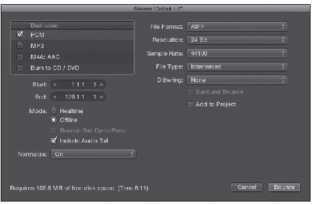
© Apple Inc.
First, you need to select the file type for your bounce:
![]() PCM: This option bounces a standard, uncompressed audio file into AIFF, Broadcast WAV, or Sound Designer II format.
PCM: This option bounces a standard, uncompressed audio file into AIFF, Broadcast WAV, or Sound Designer II format.
![]() MP3: This bounces to the MP3 compression format.
MP3: This bounces to the MP3 compression format.
![]() M4A: AAC: This bounces to either the AAC or the Apple Lossless compression format. The selected subformat will be listed after M4A, such as M4A: AAC.
M4A: AAC: This bounces to either the AAC or the Apple Lossless compression format. The selected subformat will be listed after M4A, such as M4A: AAC.
![]() Burn to CD/DVD: This burns your Logic project onto a recordable CD or DVD.
Burn to CD/DVD: This burns your Logic project onto a recordable CD or DVD.
Below the Destination section, Logic lets you enter the start and end positions of your bounce by dragging in the Start or End field, by clicking on the arrows for the desired field, or by clicking in the desired field and entering a value manually. If you have Cycle mode engaged, the start and end positions will reflect the cycle region. If you have Cycle mode disengaged and have a region selected in the main window, the start and end positions will reflect the boundaries of the selected region. Otherwise, the start and end positions will reflect the length of the entire project, as set in the Custom Transport view.
Bounce Mode Options
Once you have your start and end positions set, you can choose between Realtime or Offline mode. In Realtime mode, Logic plays the selection you want to bounce and prints the file as it is playing. The advantage of this mode is that you get to hear exactly how the bounced file will sound, and you can include the signals from input channel strips. However, it can be slow if the file is long. In Offline mode, Logic bounces your mix internally, so any external sound sources or DSP cannot be included in your bounce, with the exception of ReWire. (ReWire sources are internal to your computer, after all.) If your Logic song is not taxing your CPU, offline bouncing can be much faster than realtime bouncing. If your song squeezes every last bit of your CPU to do complex processing, offline may actually be the only way to perform a bounce. If you find this is the case, yet you want to perform a realtime bounce to ensure the bounce sounds exactly as you wish as it’s occurring, bounce your most taxing tracks in place to ease the CPU hit, and perform a realtime bounce.
Below the Realtime/Offline option buttons are two checkboxes that let you dictate a couple of very specific aspects of your bounce. The first option, Bounce 2nd Cycle Pass, works when you are bouncing a cycle region. Logic will play through one cycle of the region and then bounce the second cycle. The tails from effects such as reverbs and delays from the first pass will end up bounced at the front of the second cycle. The other option, Include Audio Tail, automatically lengthens the bounce to include all effect tails. For final mixes in particular, this option should be checked to avoid clipping your track’s end prematurely.
Normalize Options
Below the Bounce mode options is the Normalize menu, shown in Figure 11.47.
Figure 11.47 The Normalize menu.
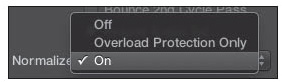
© Apple Inc.
The Normalize menu gives you three options for normalizing your bounce: Off, Overload Protection Only, and On. Normalizing means a file is scanned to find its highest peak, and the level of that peak is increased to the highest possible level (technically, 0 dBFS) without clipping, and the level of the rest of the audio is raised by the same amount. If you select Off, your bounce will not be normalized. If you select On, your bounce will be normalized in the manner described. If you select Overload Protection Only, Logic will perform a specialized normalization in which the file is scanned for overloads, and those peaks will be decreased to 0 dBFS, leaving the rest of your bounce unaltered. The Normalize feature in the Bounce dialog box is really a special feature. Be sure to read the following sidebar on it for all the details.
When to Use Logic’s Floating-Point Bounce: The Normalize functions in the Bounce dialog box are actually quite special: They use floating-point math instead of fixed-point math. That means they normalize the floating-point audio information and then map each bit to its optimal level in the final fixed-point audio file. The result is that the full dynamic range of Logic’s 64-bit floating-point audio engine is preserved much more accurately than with the traditional fixed-point Normalization feature, such as the one found in Logic’s own Audio File editor. Traditional fixed-point normalization methods may result in distortion or audio degradation, but the floating-point Normalize features of the Bounce dialog box will never compress, limit, or distort your audio.
So does this mean that you should always normalize your bounces? It depends. Here are some guidelines:
![]() If your peak levels are already at 0 dBFS, the floating-normalize feature will do absolutely nothing, so there is no point.
If your peak levels are already at 0 dBFS, the floating-normalize feature will do absolutely nothing, so there is no point.
![]() If you’re delivering your final bounce to a mastering engineer, he generally won’t want your peak levels to be at 0 dBFS, so in this case, don’t normalize your bounce.
If you’re delivering your final bounce to a mastering engineer, he generally won’t want your peak levels to be at 0 dBFS, so in this case, don’t normalize your bounce.
![]() If the levels of your audio are above 0 dBFS (in other words, if it sounds like your track is digitally clipping), be sure to normalize using the Overload Protection Only option. It will remap your audio to 0 dBFS, your audio will not be clipped anymore, and your overall bounce will maintain its accuracy.
If the levels of your audio are above 0 dBFS (in other words, if it sounds like your track is digitally clipping), be sure to normalize using the Overload Protection Only option. It will remap your audio to 0 dBFS, your audio will not be clipped anymore, and your overall bounce will maintain its accuracy.
![]() If you are bouncing a single track to be reused in your Logic project and you want to make sure you bounce at the optimal level, use the On setting.
If you are bouncing a single track to be reused in your Logic project and you want to make sure you bounce at the optimal level, use the On setting.
![]() If you’re bouncing particularly dynamic material to a compressed file format, such as MP3 or AAC, using the Normalize feature will help you get optimal dynamic range into the compressed file.
If you’re bouncing particularly dynamic material to a compressed file format, such as MP3 or AAC, using the Normalize feature will help you get optimal dynamic range into the compressed file.
As you can see, while normalization is not a cure-all or something you always want to use when you bounce, Logic’s exceptional floating-point Normalize features are extremely useful in the right circumstances.
Near the bottom of the Bounce dialog box, Logic informs you how much disk space you’ll need for your bounce and how long your file will be. You also have options to create a new folder for your bounces, to cancel the operation, and to commence the bounce.
You can bounce to multiple file formats by selecting the Destination checkboxes of more than one file type. The Bounce parameters to the right of the Destination section will change depending on which destination is highlighted (click outside the checkbox area to highlight a Destination option). The parameters for each bounce destination are explained in the following subsections.
Bounce to PCM
This bounce destination includes bouncing to uncompressed AIFF, Broadcast Wave, or Core Audio Format files. Figure 11.48 shows the PCM destination parameters.
Figure 11.48 The PCM bounce destination parameters.
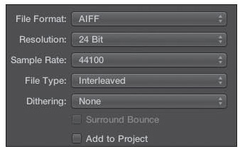
© Apple Inc.
The parameters for this bounce are as follows:
![]() File Format: This is where you select AIFF, Broadcast Wave (WAV), or Core Audio Format (CAF) for your PCM bounce. There is no sonic difference among the different formats. What format you bounce to is ultimately guided by compatibility. If you’re bouncing audio that will be imported into another DAW or across platforms, you’ll want to bounce in the most compatible format for the destination application. For example, WAV is the native audio format on PCs. If you are sending audio files to someone who is working on a PC, it will probably make the most sense to bounce your audio to WAV format. In general, if you are only working with the audio on your Macintosh, AIFF and CAF are the native formats, although AIFF is ubiquitous.
File Format: This is where you select AIFF, Broadcast Wave (WAV), or Core Audio Format (CAF) for your PCM bounce. There is no sonic difference among the different formats. What format you bounce to is ultimately guided by compatibility. If you’re bouncing audio that will be imported into another DAW or across platforms, you’ll want to bounce in the most compatible format for the destination application. For example, WAV is the native audio format on PCs. If you are sending audio files to someone who is working on a PC, it will probably make the most sense to bounce your audio to WAV format. In general, if you are only working with the audio on your Macintosh, AIFF and CAF are the native formats, although AIFF is ubiquitous.
![]() Resolution: Here you can choose the file bit depth for your bounce. Your choices are 8, 16, and 24 bit. You will almost never want to print an 8-bit bounce. If you are going straight to CD, you might want to print a 16-bit file with dither if you recorded to 24 bit (see the description of the Dithering option later in this list). Normally, you’ll want to archive your mix at 24 bits, which is the highest bit rate that Logic currently allows.
Resolution: Here you can choose the file bit depth for your bounce. Your choices are 8, 16, and 24 bit. You will almost never want to print an 8-bit bounce. If you are going straight to CD, you might want to print a 16-bit file with dither if you recorded to 24 bit (see the description of the Dithering option later in this list). Normally, you’ll want to archive your mix at 24 bits, which is the highest bit rate that Logic currently allows.
![]() Sample Rate: You can select the sample rate for your bounced file here. Logic will default to the same sample rate as your Logic song, but you can change it to any of 12 different sample rate options between 11 kHz and 192 kHz. If you select a different sample rate from the sample rate of your song, Logic will sample rate convert your bounced file using its very high quality sample rate conversion algorithms. Similar to the Resolution setting, you will generally print a file no lower than 44.1 kHz.
Sample Rate: You can select the sample rate for your bounced file here. Logic will default to the same sample rate as your Logic song, but you can change it to any of 12 different sample rate options between 11 kHz and 192 kHz. If you select a different sample rate from the sample rate of your song, Logic will sample rate convert your bounced file using its very high quality sample rate conversion algorithms. Similar to the Resolution setting, you will generally print a file no lower than 44.1 kHz.
![]() File Type: This option is available only if you are bouncing a stereo file. If your destination file is for an application that cannot import interleaved files and requires split stereo files (meaning you bounce one file for the left track and another for the right), select Split. Unless you know you need split stereo files, leave this set to Interleaved. If you are bouncing a mono file, this will be grayed out.
File Type: This option is available only if you are bouncing a stereo file. If your destination file is for an application that cannot import interleaved files and requires split stereo files (meaning you bounce one file for the left track and another for the right), select Split. Unless you know you need split stereo files, leave this set to Interleaved. If you are bouncing a mono file, this will be grayed out.
![]() Dithering: If you are bouncing 24-bit audio to a 16-bit file for CD or compressed format uses (for example, MP3 or Internet), you’ll want to turn on dithering. Normally, when you save 24-bit audio into a 16-bit file, the 8 bits that don’t make it to the 16-bit file are simply those that happen to be filling the lowest bits of the audio stream. Unfortunately, sometimes you have desired audio in those bits, and this truncation can end up sounding harsh. Dithering adds imperceptible amounts and frequencies of noise to your file so that the noise “pushes” all the desired audio into the 16 bits that are saved, and only the noise is eliminated. As you can imagine, not all dither is created equal. Logic includes the industry-standard POW-r dithering algorithms. There are three algorithms—the first is plain, and the second and third have various amounts of noise shaping to attempt to tailor the dither even more to your audio material. Logic also includes the Apogee UV22HR dithering algorithm. Use the algorithm that sounds best with your material. If you are bouncing 24-bit files, leave dithering off.
Dithering: If you are bouncing 24-bit audio to a 16-bit file for CD or compressed format uses (for example, MP3 or Internet), you’ll want to turn on dithering. Normally, when you save 24-bit audio into a 16-bit file, the 8 bits that don’t make it to the 16-bit file are simply those that happen to be filling the lowest bits of the audio stream. Unfortunately, sometimes you have desired audio in those bits, and this truncation can end up sounding harsh. Dithering adds imperceptible amounts and frequencies of noise to your file so that the noise “pushes” all the desired audio into the 16 bits that are saved, and only the noise is eliminated. As you can imagine, not all dither is created equal. Logic includes the industry-standard POW-r dithering algorithms. There are three algorithms—the first is plain, and the second and third have various amounts of noise shaping to attempt to tailor the dither even more to your audio material. Logic also includes the Apogee UV22HR dithering algorithm. Use the algorithm that sounds best with your material. If you are bouncing 24-bit files, leave dithering off.
![]() Surround Bounce: If you are bouncing for a surround mix, Logic will bounce to any of the six surround formats it supports. If you turn on Surround Bounce, this grays out the Add to iTunes Library option. Logic doesn’t do any actual surround encoding or decoding, so if you plan to do a surround bounce, you need additional hardware or software (such as Compressor, which is included in the Logic Studio bundle) to play and encode the bounced files in the proper format. Unless you need to bounce surround files, you should leave this set to Off.
Surround Bounce: If you are bouncing for a surround mix, Logic will bounce to any of the six surround formats it supports. If you turn on Surround Bounce, this grays out the Add to iTunes Library option. Logic doesn’t do any actual surround encoding or decoding, so if you plan to do a surround bounce, you need additional hardware or software (such as Compressor, which is included in the Logic Studio bundle) to play and encode the bounced files in the proper format. Unless you need to bounce surround files, you should leave this set to Off.
![]() Add to Project: This checkbox allows you to add the bounced file to the Project Audio Browser for reuse in your Logic song. This is very useful if you are bouncing only a small portion of audio to capture some effects processing or you are doing a realtime bounce to record audio from inputs and you want the result to be available for later use.
Add to Project: This checkbox allows you to add the bounced file to the Project Audio Browser for reuse in your Logic song. This is very useful if you are bouncing only a small portion of audio to capture some effects processing or you are doing a realtime bounce to record audio from inputs and you want the result to be available for later use.
Bounce to MP3
MP3 (or MPEG-1 audio layer 3) currently reigns as the ubiquitous compression format for sharing music across platforms. Figure 11.49 shows you the MP3 destination parameters.
Figure 11.49 The MP3 destination parameters.
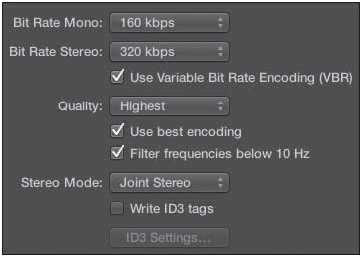
© Apple Inc.
The parameters for this bounce are as follows:
![]() Bit Rate (Mono/Stereo): You can select bit rates between 32 Kbps and 320 Kbps. Typically, bit rates of 160 Kbps or 192 Kbps offer the best balance between quality and file size for MP3 compression. The quality improvement for bit rates above 192 Kbps is minimal—you’d be better off bouncing to PCM. For mono voice sources delivered to MP3, the bit rates can generally be set lower.
Bit Rate (Mono/Stereo): You can select bit rates between 32 Kbps and 320 Kbps. Typically, bit rates of 160 Kbps or 192 Kbps offer the best balance between quality and file size for MP3 compression. The quality improvement for bit rates above 192 Kbps is minimal—you’d be better off bouncing to PCM. For mono voice sources delivered to MP3, the bit rates can generally be set lower.
![]() Use Variable Bit Rate Encoding (VBR): Select this checkbox if you want to use variable bit rate encoding instead of constant bit rate encoding. Variable bit rate encoding compresses simpler passages more heavily than more harmonically rich passages, which in theory encodes better-quality MP3s at a smaller file size.
Use Variable Bit Rate Encoding (VBR): Select this checkbox if you want to use variable bit rate encoding instead of constant bit rate encoding. Variable bit rate encoding compresses simpler passages more heavily than more harmonically rich passages, which in theory encodes better-quality MP3s at a smaller file size.
![]() Quality: If you use VBR encoding, this menu allows you to select the quality of your variable bit rate. Generally, you should keep this set to Highest. Reducing the quality speeds up the conversion process, but at the expense of audio quality. Additionally, modern computers render MP3s extremely quickly. There’s no benefit to choosing a lower setting.
Quality: If you use VBR encoding, this menu allows you to select the quality of your variable bit rate. Generally, you should keep this set to Highest. Reducing the quality speeds up the conversion process, but at the expense of audio quality. Additionally, modern computers render MP3s extremely quickly. There’s no benefit to choosing a lower setting.
![]() Use Best Encoding: If you deselect this checkbox, you gain encoding speed at the price of audio quality. Again, you should always keep this setting selected.
Use Best Encoding: If you deselect this checkbox, you gain encoding speed at the price of audio quality. Again, you should always keep this setting selected.
![]() Filter Frequencies Below 10 Hz: Frequencies below 10 Hz are usually not reproduced by speakers and are not audible to human ears anyway. Such frequencies can, however, create a muddier MP3. If you select this checkbox, Logic removes those frequencies, leaving slightly more data bandwidth for the frequencies that people can hear and resulting in an improvement in perceived quality.
Filter Frequencies Below 10 Hz: Frequencies below 10 Hz are usually not reproduced by speakers and are not audible to human ears anyway. Such frequencies can, however, create a muddier MP3. If you select this checkbox, Logic removes those frequencies, leaving slightly more data bandwidth for the frequencies that people can hear and resulting in an improvement in perceived quality.
![]() Stereo Mode: You can choose between Joint Stereo and Normal Stereo modes. The differences are very subtle, if any, so go ahead and experiment to see which sounds better on your source material. Don’t be surprised if both sound the same. This option is not available for mono bounces.
Stereo Mode: You can choose between Joint Stereo and Normal Stereo modes. The differences are very subtle, if any, so go ahead and experiment to see which sounds better on your source material. Don’t be surprised if both sound the same. This option is not available for mono bounces.
![]() Write ID3 Tags: MP3 files can have ID information, such as song title, artist, and so on, encoded with the audio. If you want to enter this information for your bounce, select this checkbox.
Write ID3 Tags: MP3 files can have ID information, such as song title, artist, and so on, encoded with the audio. If you want to enter this information for your bounce, select this checkbox.
![]() ID3 Settings: If you select the Write ID3 Tags checkbox, this button will become available. Click it to open a window in which you can enter the song title, artist, album, genre, and other information. ID3 tags are useful if you plan to share your MP3 or you want the information to display in iTunes. Otherwise, there’s no need to bother.
ID3 Settings: If you select the Write ID3 Tags checkbox, this button will become available. Click it to open a window in which you can enter the song title, artist, album, genre, and other information. ID3 tags are useful if you plan to share your MP3 or you want the information to display in iTunes. Otherwise, there’s no need to bother.
Bounce to M4A: AAC
Advanced Audio Coding (AAC) and Apple Lossless are the “next generation” of audio encoding, based on the MP4 (MPEG-4) format, the successor to MP3. Figure 11.50 shows you the M4A: AAC destination parameters.
Figure 11.50 The M4A: AAC destination parameters.
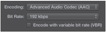
© Apple Inc.
AAC produces better audio quality at the same bit rate as MP3. Apple Lossless is a format that compresses the audio to a smaller file size than an uncompressed format with absolutely no loss of data or quality. AAC and Apple Lossless files can be decoded by iTunes (and, therefore, iPods, iPads, and iPhones), and by QuickTime on Mac OS X and Windows PCs. AAC is also compatible with some other media players and is used by the iTunes Music Store for its commercially available songs.
When you select M4A in the Destination area, there are only three visible options.
![]() Encoding: You can choose to encode your audio in AAC or Apple Lossless format.
Encoding: You can choose to encode your audio in AAC or Apple Lossless format.
![]() Bit Rate: You can choose the bit rate of your AAC file from between 16 Kbps and 320 Kbps. Typically, a bit rate of 160 Kbps or 192 Kbps offers the best balance between quality and file size for AAC compression. The quality improvement for bit rates above 192 Kbps is minimal. If you are bouncing in Apple Lossless format, this option is grayed out.
Bit Rate: You can choose the bit rate of your AAC file from between 16 Kbps and 320 Kbps. Typically, a bit rate of 160 Kbps or 192 Kbps offers the best balance between quality and file size for AAC compression. The quality improvement for bit rates above 192 Kbps is minimal. If you are bouncing in Apple Lossless format, this option is grayed out.
![]() Encode with Variable Bit Rate (VBR): Select this checkbox if you want to use variable bit rate encoding instead of constant bit rate encoding. Variable bit rate encoding compresses simpler passages more heavily than more harmonically rich passages, which in theory encodes better-quality AACs at a smaller file size. If you are bouncing in Apple Lossless format, this option is grayed out.
Encode with Variable Bit Rate (VBR): Select this checkbox if you want to use variable bit rate encoding instead of constant bit rate encoding. Variable bit rate encoding compresses simpler passages more heavily than more harmonically rich passages, which in theory encodes better-quality AACs at a smaller file size. If you are bouncing in Apple Lossless format, this option is grayed out.
Bounce to CD/DVD
This option lets you bounce your Logic project directly to a CD or DVD—in other words, to burn it. This option does not allow you the complete facilities for properly mastering a commercial CD. If you want to quickly bounce your Logic project to a CDR/CD-RW or DVD to audition it in various stereo or surround systems, to share with friends, and so on, this option will do the trick. Figure 11.51 shows the Burn destination parameters.
Figure 11.51 The Burn destination parameters.
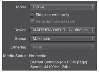
© Apple Inc.
The parameters for this bounce are as follows:
![]() Mode: This menu allows you to choose between CDDA (Compact Disc Digital Audio) and DVD-A (Digital Versatile Disc Audio).
Mode: This menu allows you to choose between CDDA (Compact Disc Digital Audio) and DVD-A (Digital Versatile Disc Audio).
![]() Simulate Write Only: If you want to try a test run to make sure everything is set up and working properly to do a CDDA or a DVD-A burn, select this checkbox.
Simulate Write Only: If you want to try a test run to make sure everything is set up and working properly to do a CDDA or a DVD-A burn, select this checkbox.
![]() Write as Multi-Session: If you select this checkbox, you will be able to write other files to a CD-R after you burn your Logic project. If this checkbox is deselected, Logic will “close” the CD-R when it is finished. If you want to use your CD-R for more material, select this checkbox. Otherwise, leave it deselected. If you are bouncing to DVD-A, this option is grayed out.
Write as Multi-Session: If you select this checkbox, you will be able to write other files to a CD-R after you burn your Logic project. If this checkbox is deselected, Logic will “close” the CD-R when it is finished. If you want to use your CD-R for more material, select this checkbox. Otherwise, leave it deselected. If you are bouncing to DVD-A, this option is grayed out.
![]() Device: This menu allows you to select any connected CD or DVD burner.
Device: This menu allows you to select any connected CD or DVD burner.
![]() Speed: This menu allows you to select the maximum speed your CD or DVD burner can write to disc or any lower speed your drive is capable of. How many options appear here will depend on your model of drive.
Speed: This menu allows you to select the maximum speed your CD or DVD burner can write to disc or any lower speed your drive is capable of. How many options appear here will depend on your model of drive.
![]() Dithering: Refer to the “Dithering” bullet in the “Bounce to PCM” section earlier in this chapter.
Dithering: Refer to the “Dithering” bullet in the “Bounce to PCM” section earlier in this chapter.
![]() Media Status: This tells you what kind of disc is in the selected drive.
Media Status: This tells you what kind of disc is in the selected drive.
The Current Settings (on PCM Page) section at the bottom informs you of your current PCM settings for a bounce. The current PCM bounce settings are what will be bounced to CD or DVD, regardless of whether PCM is checked or not. If you want a different sample rate and bit depth for your CD or DVD bounce, change those settings for the PCM bounce settings.
Including MIDI Tracks in Your Bounce: Clearly, bouncing your audio tracks from an output channel strip includes only audio. What if you want to include the output of your MIDI hardware modules in your bounce file?
There are two ways to go about this. The first method requires that before you do your final bounce, you record the output of your external MIDI hardware into audio tracks in Logic. This takes extra time but allows you to move and edit your newly recorded external MIDI audio as you would any other audio performance, which you may enjoy. Once your external MIDI has been committed to audio tracks, Logic bounces them with all your other audio tracks. This is especially easy if you use the External Instrument effect as described in Chapter 9.
If you want to keep your MIDI hardware in the MIDI realm as long as possible and never record it as audio, one way to do this is simply to delay the aforementioned step until right before you print your final bounce. However, if you know that you’ll never want to record your MIDI in advance, you can instead create input channel strips for all your MIDI hardware modules. Because input channel strips are audio channel strips, you can mix, process, and bounce them to a file just like the audio on any other audio channel strip. Using input channel strips requires that you have as many physical hardware inputs as you have MIDI module outputs you want to use. Creating input channel strips is a bit more complicated because you can’t create them in the main window; you can only create them in the Mixer layer of the Environment. But using the Mixer layer of the Environment, you can create an entire “input mixer” if you want, for just this sort of thing.
Also, to compensate for your audio hardware latency, you may need to adjust the Delay transmission by setting, which you can access by choosing File > Project Settings > Synchronization and clicking the MIDI tab. If you don’t know exactly how much latency your audio hardware has, and its documentation lists no approximations in milliseconds, you can use trial and error to determine the point at which your audio sounds in sync with your MIDI.
Surround Mixing
In addition to allowing for the usual stereo mixing, Logic Pro X includes complete, comprehensive, and arguably best-in-class support for surround mixing, including surround effects, panning, and bouncing functions. Logic supports the most common surround formats (such as quad, Pro Logic, 5.1, and 7.1) and even some additional, more esoteric surround formats. To access Logic’s surround functions, you must have audio hardware with more than two physical outputs. Logic also offers surround upmixing and downmixing in software.
Changing an audio channel strip from a mono or a stereo channel to a surround channel is very simple. Click and hold the Format button; then, in the menu that opens, select Surround, as shown in Figure 11.52.
Figure 11.52 If you want an audio channel strip to be a surround object, select Surround from the Format menu.
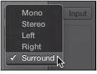
© Apple Inc.
When an audio channel strip is placed in Surround mode, its Panorama dial is replaced by a special Surround control, as shown in Figure 11.53. The surround speakers are represented by white dots and the pan position by a green dot. You can grab the green dot and rotate it anywhere around the Surround control. Note that you can mix stereo and surround objects in the same Logic song with no restrictions.
Figure 11.53 After placing an audio channel strip in Surround mode, its Pan dial changes into a special Surround panorama control.
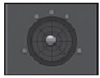
© Apple Inc.
The Surround Panner Window
If you double-click the Surround control on a surround channel, you will open a Surround Panner window, shown in Figure 11.54. This gives you a more detailed view of the surround panorama, as well as access to the surround format, LFE Level setting, and Center Level setting.
Figure 11.54 In the Surround Panner window, you can access the surround format, LFE Level setting, and Center Level setting, and also see a more detailed image of the surround panorama.
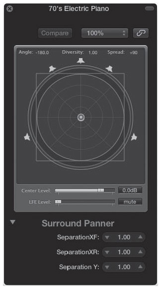
© Apple Inc.
The Surround Panner window offers you more options than just grabbing and moving your signal in the surround panorama. To lock the diversity, you can press the Command button while dragging the blue dot. You can also press Command+Option while dragging lock the angle, and you can press Option to reset the angle and radius to the exact center.
The slider at the bottom of the window is the LFE (Low Frequency Enhancement) Level control. Generally, the LFE channel is a subwoofer, but it doesn’t have to be. This slider controls how much of the signal from this channel is directed toward the LFE channel. The Center Level slider determines signal level at the dead center of the surround panorama.
The extended parameters area offers three controls:
![]() Separation XF: Separation XF changes the separation of the front left and right channels.
Separation XF: Separation XF changes the separation of the front left and right channels.
![]() Separation XR: Separation XR changes the separation of the rear left and right channels.
Separation XR: Separation XR changes the separation of the rear left and right channels.
![]() Separation Y: Separation Y changes the separation of the front and rear speakers.
Separation Y: Separation Y changes the separation of the front and rear speakers.
Assigning Surround Channels to Audio Outputs
You determine which physical output will correspond to which surround channel in the Output screen of the I/O Assignments tab of the Audio Preferences window. You can access the Audio Preferences window from the global menus by choosing Logic Pro > Preferences > Audio. Clicking the I/O Assignments tab opens the Output screen by default (see Figure 11.55).
Figure 11.55 The Output screen of the I/O Assignments tab of the Audio Preferences window.
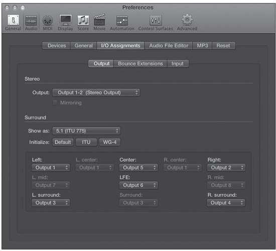
© Apple Inc.
In the Show As menu, you can select which surround format Logic will output. At this point, the appropriate menus are accessible for assigning your hardware outputs to the surround channels dictated by your chosen surround format. You might want to place a low-pass filter effect into the Audio FX slot of the output object that is your LFE, since that is the standard LFE cut off for surround subwoofer channels. The three buttons under the Show As menu allow you to automatically select the Default, ITU, or WG-4 configuration of hardware outputs rather than having to set each menu manually.
Applying Surround Effects
Logic supports the use of surround effects, and some of Logic’s own effects have native 5.1 support. You can insert stereo 5.1 effects on stereo channel strips and 5.1 effects on surround channel strips, such as surround software instrument channel strips and master channel strips.
Applying Surround Effects to a Surround Channel Strip
Inserting a surround effect on a surround channel strip is just as easy as inserting a stereo effect in a stereo channel strip. Simply select an Insert slot, navigate to the effect you would like to insert, and then select whichever format the plug-in offers for your project’s surround format, such as 5.1 or Multi Mono, as shown in Figure 11.56.
Figure 11.56 A Multi Mono effect being instantiated on a surround channel strip.
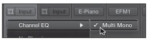
© Apple Inc.
When you instantiate a Multi Mono effect, you’ll notice that the plug-in window’s Editor view offers new tabs that are unavailable on stereo or mono effects (see Figure 11.57).
Figure 11.57 The Editor view of a Multi Mono effect. Notice the Configuration, L-R|Ls-Rs|C, and LFE tabs.
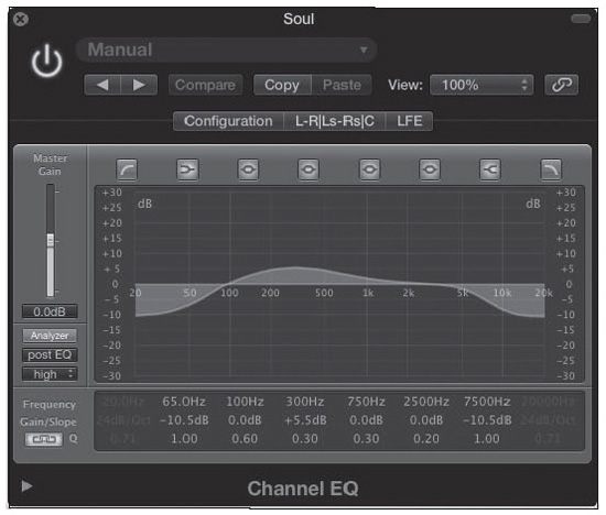
© Apple Inc.
The Configuration tab allows you to alter the content and number of the remaining tabs. Clicking the Configuration tab reveals a new set of controls in the plug-in window, as shown in Figure 11.58.
Figure 11.58 Clicking the Configuration tab reveals a new set of controls in the plug-in window.
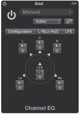
© Apple Inc.
The Link menus under each surround channel in the Configuration tab allow you to assign each channel to a linked group: A, B, C, or –. Each Link group has its own tab, which appears as channels are added to that group. Each tab basically allows the effect to act as a dedicated effects unit for the channels assigned to that tab. The – option assigns the selected channel to its own individual tab. You can see in Figure 11.59 that the L, C, and R channels have all linked in the same tab; that the Ls and Rs channels are each assigned to discrete tabs; and that the LFE channel is bypassed. That means the L, C, and R channels are being processed with the same plug-in setting, while the Ls and Rs channels can each be processed separately within the same plug-in instance and the LFE channel undergoes no processing. You can save these configuration and effects settings as presets for recall at a later time.
Figure 11.59 The L, C, and R channels coming through this effect have been linked to group A, allowing them to be processed together. The Ls and Rs tabs are being processed individually, while the LFE channel is not being processed.
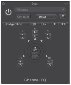
© Apple Inc.
Note that when you use the side chain on a side chain–capable plug-in, the source audio is routed to all surround channels and the side-chain detection is linked, so that the plug-in can maintain the integrity of the surround image.
Applying Surround Effects to a Mono or Stereo Channel Strip
If your audio interface supports six or more outputs, inserting a Mono > Surround or Stereo > Surround plug-in on a mono or stereo channel whose output has automatically been assigned to Surround changes the level meters of the channel to surround metering, as shown in Figure 11.60. The Mono > Surround or Stereo > Surround option should reflect your project’s surround format, meaning that if your project is in 5.1, then a surround plug-in inserted on a stereo channel will be instantiated as a Stereo > 5.1 format plug-in.
Figure 11.60 A mono audio channel strip whose output has been set to Surround. When you instantiate a Mono > Surround or Stereo > Surround effect in an Audio FX slot, like Delay Designer in this instance, the level meters switch to surround metering. Note that the Format button of the channel strip still displays the mono symbol.
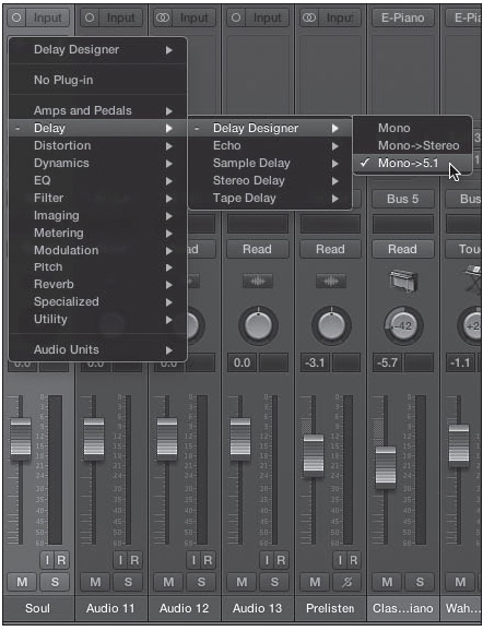
© Apple Inc.
Effects that are inserted before the Mono > Surround or Stereo > Surround effect maintain the channel strip’s original format. Effects inserted after the Mono > Surround or Stereo > Surround effect can be either Multi Mono or Surround, depending on what format(s) the plug-in supports.
Using the Down Mixer Plug-In
The Down Mixer plug-in, found in the Utility submenu of the master channel strip’s Audio FX slots, allows you to change the format of the master channel strip from Surround to Stereo, Quad, or LCRS (Pro Logic). This gives you the ability to quickly check how your surround mix sounds in another format. Figure 11.61 shows a Down Mixer 5.1 To Stereo instance. The level controls allow you to change the levels of different channel groupings, along with the overall signal level.
Figure 11.61 The Down Mixer plug-in. This master channel strip plug-in allows you to quickly check the compatibility of your surround mix in different formats.
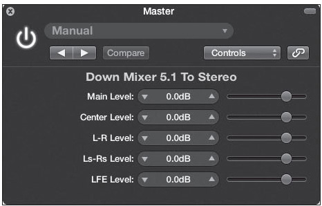
© Apple Inc.
The Surround Compressor
There is one other Logic effect worth mentioning: the Surround Compressor. Although it is outside the scope of this book to go into detail about the Surround Compressor, it bears mentioning because this effect is available only on surround channel strips. It functions like any typical compressor, but it is specifically designed for surround application, with the Link menus of a Multi Mono plug-in available directly in its Editor view.
Bouncing in Surround
As mentioned, you can choose to bounce in surround by selecting Surround Bounce in the Bounce dialog box. Logic gives the files the extensions shown in the Bounce Extensions screen in the I/O Assignments tab of the Audio Preferences window, as shown in Figure 11.62.
Figure 11.62 The Bounce Extensions screen of the I/O Assignments tab of the Audio Preferences window.
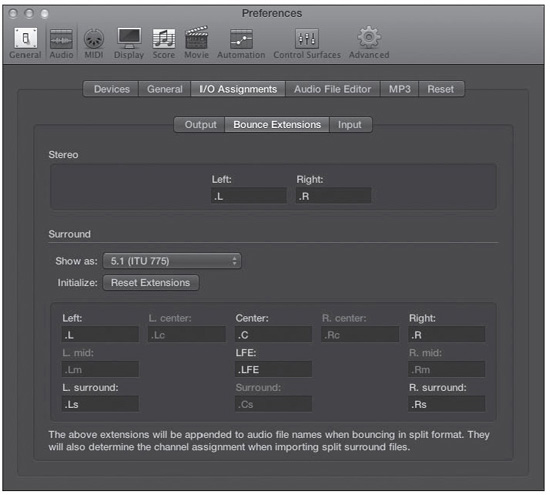
© Apple Inc.
Mixing Using Control Surfaces
Setting up a control surface with Logic was discussed in Chapter 3. But considering that most control surfaces are geared toward mixing, I wanted to briefly bring them up again here.
Depending on how you like to work, these devices can be a godsend. They let you manipulate more than one fader, Pan knob, and so on at a time. Control surfaces usually let you adjust plug-in parameters as well, and as with faders, you can control multiple parameters simultaneously. You can use a control surface to record automation for one or more tracks at a higher resolution than you can using a mouse. They usually include Transport controls to start and stop the song. The more advanced controllers also include shortcut buttons for advanced automation, editing, and other useful functions. As you can see, control surfaces can help you mix both more quickly and more accurately.
Control surfaces range from small plastic devices with a few knobs and sliders that cost less than most Audio Units plug-ins, to completely professional full-size mixers that cost hundreds of thousands of dollars. This book can’t possibly cover all the different types of control surfaces and ways in which control surfaces can be connected and used with Logic Pro. However, I did want to mention a few controllers.
The Avid Artist series of controllers for audio applications consists of the Artist Control, the Artist Mix, and the Artist Transport. These controllers look like Mac products for good reason: Apple was involved in their development before Avid bought the original manufacturer, Euphonix, and they were created with Logic in mind. Avid has a long and well-earned reputation for making high-end, professional audio products, and if you can afford these controllers, you won’t be disappointed.
The Artist Control was designed to be a complete editing and mixing “brain” that gives you one-button touchscreen access to as many editing, arranging, and mixing features as you like. You can add Artist Mix units for a system offering as many high-quality, touch-sensitive motorized faders as you need. Euphonix also invented its own high-end, two-way communication protocol between control surface and software program, called EuCon. Avid has continued that protocol, which is supported by most media applications, including Logic. You can learn more about the Avid Artist series at www.avid.com.
Many years ago, the controller that initially blew open the controller market was the Logic Control, designed by Mackie. Today’s Mackie MCU Pro series of controllers is the direct descendant of that original Logic-only control surface. And this controller truly is universal: Most software and controller devices support Mackie Control emulation (including the Avid Artist series). The Mackie Controllers (or the Mackie Control protocol) are not as robust as the Avid Artist series, but they are extremely capable. You can read more about them at www.mackie.com/products/mcupro.