
3 The Logic Project
AN IMPORTANT DISTINCTION BETWEEN LOGIC AND OTHER MUSIC WORKSTATION APPLICATIONS is just how much information is stored in each document file, which is called a project in Logic. In most applications, you set up the application the way you want to by arranging windows, toolbars, and so on. When you load a document, that document uses the application configuration. In Logic, the project contains everything about your studio—the setup of all your instruments, editors, windows, screensets, and everything else that is configurable in Logic. In fact, each project in Logic is a self-contained virtual studio. That means if you create a project in your copy of Logic and then open it in someone else’s copy of Logic, you will still find your own familiar virtual studio waiting for you.
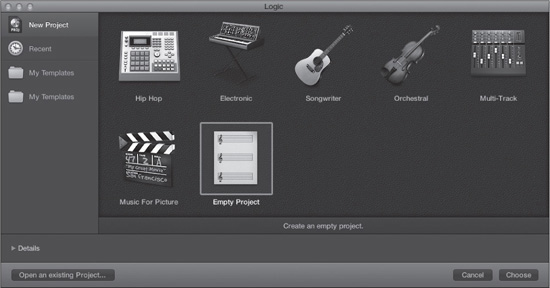
When you launch Logic for the first time, it automatically presents you with a selection of different templates in the Project Chooser. These templates represent Apple’s effort to provide an array of ready-made project setups that people will find generally useful. Figure 3.1 shows the Project Chooser.
Figure 3.1 The Project Chooser. When you first launch Logic, or when you use the File > New command, the Project Chooser opens.
© Apple Inc.
Templates are blank songs with a specific configuration from which you might want to start. Apple’s templates are stored in the Application Support folder for Logic, which you can find at/Library/Application Support/Logic/Project Templates. This chapter deals with creating and saving your own custom template, which will help you get right down to the business of creating music every time you open Logic.
You should explore the templates that Apple includes with Logic to get a feel for the myriad ways you can configure Logic. Apple has included templates for uses as varied as electronic music composition, music for picture, and multi-track recording. To open a template in the Project Chooser, simply click on its icon and then click the Choose button. Each time you close a template, you can access the Project Chooser by selecting File > New from Template or pressing Command+N.
After you have explored some of these templates, open an empty project by doing the following:
1. Select File > New from Template or press Command+N.
2. Click on the Empty Project option.
3. Click the Choose button.
TIP: You can also access an empty project by selecting File > New or by pressing Shift+Command+N.
You’ll use this empty project to create your template. When complete, you will be able to select this template to have Logic immediately open into your personal virtual studio instead of a general default song.
Don’t worry about the Details area that you access by clicking the disclosure triangle at the bottom-left corner of the Project Chooser. Some of its options are unnecessary for a template, and the other options you’ll set up manually to help you understand how to change things like your audio inputs and outputs when needed. The Details area is covered in Chapter 12, “Working with and Sharing Files.”
Trust me on this: Creating your template project is one of the most important things you will do in Logic! The actual mechanics involved in creating a template couldn’t be simpler:
1. You set up a Logic project.
2. You name the Logic project.
3. You select File > Save As Template.
Exactly how you set up the template, however, involves some serious thought and preparation. Creating your template project is a continuous process. As you learn more about Logic and your working preferences, you can always go back and change your template project accordingly. You can even create a number of different templates designed for different purposes, much like the templates that Apple has included with Logic. To get you started, here are a few points that you need to consider.
Visualizing Your Workspace
The first and most important aspect of creating a template project is to have a general idea of what aspects of the program you’ll want to access. Chapter 2, “A Quick Tour of Logic Pro,” gave you an overview of some of the windows and editors in Logic. Did you already get a sense of which ones you expect to use the most? Do you imagine yourself needing the main window and the Audio File editor all the time, the Piano Roll editor a little, and the Score editor not at all? Do you imagine that your most important windows will be the Score editor and Event List editor, and then the main window and the Mixer? Do you need to access Environment objects creatively for each composition? You don’t need to know how to use all the windows and editors yet—that’s what the rest of the book is for. For now, consider how you might want to work and which windows you’ll want to have readily available.
Next, consider how much screen real estate you have. Do you have dual 27-inch screens so you can spread out everything you’ll need at once? Are you making do with a 13-inch laptop screen? Do you like to work with one single window on the screen at one time, or do you like to have each editor in its own separate window? Luckily, Logic’s screensets allow you to build your template project to fit any of these configurations; all you need to have is a general idea of where you’d like to start.
Remember, the core idea behind Logic is to be as configurable as possible to allow you the flexibility to create your own ideal workspace. If you have an inkling of what the makeup of that ideal space will be, then it will be that much easier to create it. The name of the game here is experimentation. If you’re not sure you’ll have enough room for an editor, open the editor in the Editors area of the main window. You could even open it in its own window, resize it, move it around, and see how it feels to use it in that size and position. When you’re comfortable with Logic, rearranging your template will be as simple as opening the application, placing the window you need in the screenset you desire, perhaps locking the screenset (explained later in this chapter in the section “Setting Up Screensets”), and resaving the project. For now, with just what has already been discussed and a bit of careful planning, you can already set up an almost optimal template project.
Creating Your Template
Not too long ago, creating a new workspace from scratch in Logic meant getting your hands dirty and digging around in menus and the Environment. Having to figure out how to create and configure instrument objects, audio objects, Environment Mixers, and so forth helped add to the impression that Logic was an application with a very steep learning curve. The process is so much simpler these days that getting a template started with a full complement of audio, software instrument, and external MIDI tracks takes little more than a few mouse clicks and keystrokes.
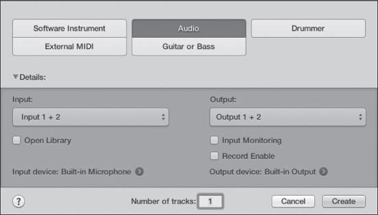
To begin creating your template project, select Empty Project in the Project Chooser (if you do not already have an empty project open). When you create an empty project, you are greeted with an empty main window showing a New Tracks dialog box, as shown in Figure 3.2. In the New Tracks dialog box, you can add and configure audio, software instruments, Drummer tracks, guitar or bass tracks, and external MIDI tracks. Let’s begin by adding some audio tracks to the empty project.
Figure 3.2 The New Tracks dialog box.
© Apple Inc.
Adding Audio Tracks
To add audio tracks to your project, click the Audio button in the New Tracks dialog box. Figure 3.2 shows the new audio track options. In the Number of Tracks field, enter the number of audio tracks you would like to add to your project. (Don’t worry about getting it right the first time. You can always add more tracks later.) You then need to configure your audio tracks. Click the Details disclosure triangle to access the configuration parameters. The New Tracks dialog box gives you the following options for configuring your audio tracks so they’ll be ready to go immediately after creation:
![]() Input: The Input menu allows you to assign hardware inputs, buses, or no input to your new audio tracks. With no-input tracks, you can configure the input later if desired. If you select a single input, Input 1 for example, all your new audio tracks will be mono. If you choose a paired input—for example, Input 1 + 2—your new audio tracks will be stereo. If you choose Surround as the format for your new audio tracks, Logic will configure your hardware inputs per the assignment in the Input screen of the I/O Assignments tab of the Audio Preferences window, covered in the section “Configuring Surround Inputs” later in this chapter. You also have the option of selecting No Input or a bus for the input of surround audio tracks. If you are creating more than one new audio track assigned to hardware inputs or to buses and you select the Ascending option at the top of the Input menu, Logic will automatically assign hardware inputs or buses to your new audio tracks in ascending order. Alternatively, suppose you are assigning your new audio tracks to hardware inputs and are creating more new audio tracks than you have hardware inputs. In that case, after Logic has assigned all your hardware inputs to audio tracks, Logic will start back at hardware input 1 and continue assigning subsequent inputs in ascending order. Therefore, if you create 10 new mono audio tracks and select the Ascending option, but you have only eight hardware inputs, Logic will assign audio tracks 1–8 to hardware inputs 1–8, respectively, and then assign audio track 9 to hardware input 1 and audio track 10 to hardware input 2.
Input: The Input menu allows you to assign hardware inputs, buses, or no input to your new audio tracks. With no-input tracks, you can configure the input later if desired. If you select a single input, Input 1 for example, all your new audio tracks will be mono. If you choose a paired input—for example, Input 1 + 2—your new audio tracks will be stereo. If you choose Surround as the format for your new audio tracks, Logic will configure your hardware inputs per the assignment in the Input screen of the I/O Assignments tab of the Audio Preferences window, covered in the section “Configuring Surround Inputs” later in this chapter. You also have the option of selecting No Input or a bus for the input of surround audio tracks. If you are creating more than one new audio track assigned to hardware inputs or to buses and you select the Ascending option at the top of the Input menu, Logic will automatically assign hardware inputs or buses to your new audio tracks in ascending order. Alternatively, suppose you are assigning your new audio tracks to hardware inputs and are creating more new audio tracks than you have hardware inputs. In that case, after Logic has assigned all your hardware inputs to audio tracks, Logic will start back at hardware input 1 and continue assigning subsequent inputs in ascending order. Therefore, if you create 10 new mono audio tracks and select the Ascending option, but you have only eight hardware inputs, Logic will assign audio tracks 1–8 to hardware inputs 1–8, respectively, and then assign audio track 9 to hardware input 1 and audio track 10 to hardware input 2.
![]() Output: The Output menu allows you to assign your new audio tracks to hardware outputs, buses, no output, or surround. If you select No Output, you can configure the output later if desired. As with the Input menu, if you select a single output or a paired output, all subsequent outputs will be mono or stereo, respectively. If you select Surround as your output format, Logic will configure your hardware outputs per the assignment in the Output screen of the I/O Assignments tab of the Audio Preferences window. Surround outputs and the Output screen of the I/O Assignments tab of the Audio Preferences window are covered in detail in Chapter 11, “Mixing in Logic.” If you are creating more than one new audio track assigned to hardware outputs or to buses and you select the Ascending option at the top of the Output menu, Logic will automatically assign hardware outputs or buses to your new audio tracks in ascending order. Alternatively, suppose you are assigning your new audio tracks to hardware outputs and are creating more new audio tracks than you have hardware outputs. In that case, once Logic has assigned all your hardware outputs to audio tracks, Logic will start back at hardware output 1 and continue assigning subsequent outputs in ascending order.
Output: The Output menu allows you to assign your new audio tracks to hardware outputs, buses, no output, or surround. If you select No Output, you can configure the output later if desired. As with the Input menu, if you select a single output or a paired output, all subsequent outputs will be mono or stereo, respectively. If you select Surround as your output format, Logic will configure your hardware outputs per the assignment in the Output screen of the I/O Assignments tab of the Audio Preferences window. Surround outputs and the Output screen of the I/O Assignments tab of the Audio Preferences window are covered in detail in Chapter 11, “Mixing in Logic.” If you are creating more than one new audio track assigned to hardware outputs or to buses and you select the Ascending option at the top of the Output menu, Logic will automatically assign hardware outputs or buses to your new audio tracks in ascending order. Alternatively, suppose you are assigning your new audio tracks to hardware outputs and are creating more new audio tracks than you have hardware outputs. In that case, once Logic has assigned all your hardware outputs to audio tracks, Logic will start back at hardware output 1 and continue assigning subsequent outputs in ascending order.
![]() Input Monitoring: Selecting the Input Monitoring checkbox activates your new audio tracks’ input monitoring buttons, allowing you to monitor signals passing through your new audio tracks’ channel strips when the audio tracks are not record enabled. Beware that if you have any live mic sources hooked up and your monitoring is turned on—for example, you are working on your laptop and the built-in mic is your input device and the built-in speakers are your output device—expect to get a good dose of feedback. Always be mindful of your levels!
Input Monitoring: Selecting the Input Monitoring checkbox activates your new audio tracks’ input monitoring buttons, allowing you to monitor signals passing through your new audio tracks’ channel strips when the audio tracks are not record enabled. Beware that if you have any live mic sources hooked up and your monitoring is turned on—for example, you are working on your laptop and the built-in mic is your input device and the built-in speakers are your output device—expect to get a good dose of feedback. Always be mindful of your levels!
![]() Record Enable: Selecting the Record Enable checkbox activates your new audio tracks’ Record Enable button, allowing you to begin recording to your new audio tracks almost immediately.
Record Enable: Selecting the Record Enable checkbox activates your new audio tracks’ Record Enable button, allowing you to begin recording to your new audio tracks almost immediately.
![]() Open Library: Selecting the Open Library checkbox opens the Library in the main window when you create your new audio tracks, allowing you to instantly access channel-strip settings for your new audio channel strips.
Open Library: Selecting the Open Library checkbox opens the Library in the main window when you create your new audio tracks, allowing you to instantly access channel-strip settings for your new audio channel strips.
![]() Input Device: The Input Device field shows the currently selected input device for Logic. Clicking the right-arrow button to the right of the currently selected input device opens the Devices tab of the Audio Preferences window. This tab is covered in the section “Setting Up Your Hardware” later in this chapter.
Input Device: The Input Device field shows the currently selected input device for Logic. Clicking the right-arrow button to the right of the currently selected input device opens the Devices tab of the Audio Preferences window. This tab is covered in the section “Setting Up Your Hardware” later in this chapter.
![]() Output Device: The Output Device field shows the currently selected output device for Logic. Clicking the right-arrow button to the right of the currently selected output device opens the Devices tab of the Audio Preferences window. After you have configured all the options in the New Tracks dialog box, click the Create button, and the specified number of new audio tracks will be created. Your new audio tracks will be visible in the main window and channel strips for each new audio track will be added to the Mixer. Channel strips will also be created in the Mixer layer of the Environment for each new audio track.
Output Device: The Output Device field shows the currently selected output device for Logic. Clicking the right-arrow button to the right of the currently selected output device opens the Devices tab of the Audio Preferences window. After you have configured all the options in the New Tracks dialog box, click the Create button, and the specified number of new audio tracks will be created. Your new audio tracks will be visible in the main window and channel strips for each new audio track will be added to the Mixer. Channel strips will also be created in the Mixer layer of the Environment for each new audio track.
What if you created eight mono audio tracks, but you would like to add eight stereo audio tracks? You can open the New Tracks dialog box by doing one of the following:
![]() Clicking the left-most plus symbol(+) at the top of the track list
Clicking the left-most plus symbol(+) at the top of the track list
![]() Selecting Track > New Tracks
Selecting Track > New Tracks
![]() Pressing Option+Command+N
Pressing Option+Command+N
If you want to add a track that is identical to a track you have selected in the track list, you can do one of the following:
![]() Select Track > Other > New Track With Duplicate Settings.
Select Track > Other > New Track With Duplicate Settings.
![]() Press Command+D.
Press Command+D.
![]() Click the right-most plus symbol at the top of the track list.
Click the right-most plus symbol at the top of the track list.
The new tracks will appear directly below the selected track in the track list, and the new track will be selected.
Configuring the Audio Track Inspector
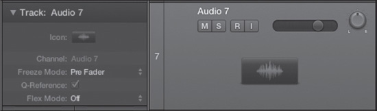
Although all the parameters you need to get started are configured using the New Tracks dialog box, there are a couple of other options you may want to change in the Track Inspector. Each track has its own Track Inspector, although if a track shares a channel strip with other tracks, then they all share the same Track Inspector. Figure 3.3 shows an audio track and its Track Inspector.
The audio Track Inspector options are as follows:
![]() Track name: If you know what sources you are going to assign to a particular audio track, you can double-click on the default name to the right of the disclosure triangle—Audio 7 in Figure 3.3. Logic will display a text box in which you can type the new track name. For example, if you know Audio 7 will always be a kick drum, you could name the track “Kick Drum.”
Track name: If you know what sources you are going to assign to a particular audio track, you can double-click on the default name to the right of the disclosure triangle—Audio 7 in Figure 3.3. Logic will display a text box in which you can type the new track name. For example, if you know Audio 7 will always be a kick drum, you could name the track “Kick Drum.”
Figure 3.3 An audio track and its Track Inspector.
© Apple Inc.
![]() Icon: Use this setting to select the icon you want to represent the audio track. If you click and hold the mouse pointer on the image, Logic will display a menu of available icons, categorized by type. If you know that certain audio tracks will always be for a particular purpose—for example, audio track 1 will always be a vocal track and audio track 2 will always be the bass track—then feel free to assign an appropriate icon to each track.
Icon: Use this setting to select the icon you want to represent the audio track. If you click and hold the mouse pointer on the image, Logic will display a menu of available icons, categorized by type. If you know that certain audio tracks will always be for a particular purpose—for example, audio track 1 will always be a vocal track and audio track 2 will always be the bass track—then feel free to assign an appropriate icon to each track.
![]() Freeze Mode: The Freeze Mode parameter lets you specify whether the track will include effects in the resulting Freeze file if you freeze the track. The Freeze Mode parameter and Freeze tracks are covered in Chapter 6, “The Logic Pro Main Window.”
Freeze Mode: The Freeze Mode parameter lets you specify whether the track will include effects in the resulting Freeze file if you freeze the track. The Freeze Mode parameter and Freeze tracks are covered in Chapter 6, “The Logic Pro Main Window.”
![]() Q-Reference: Logic Pro X lets you easily quantize audio. With the Q-Reference button selected, the audio track will give its region’s transients as quantization reference points. Q-Reference and quantizing audio are covered in Chapter 6.
Q-Reference: Logic Pro X lets you easily quantize audio. With the Q-Reference button selected, the audio track will give its region’s transients as quantization reference points. Q-Reference and quantizing audio are covered in Chapter 6.
![]() Flex Mode: In addition to quantizing audio, Logic Pro X lets you treat audio in an elastic manner, changing the timing of an audio file in a nondestructive manner. The Flex Mode parameter helps you define what kind of Flex Time editing process will work on the audio. You can also select Flex Pitch Editing mode using the Flex Mode parameter. Flex Time and Flex Pitch editing and the Flex Mode menu are covered in Chapter 6.
Flex Mode: In addition to quantizing audio, Logic Pro X lets you treat audio in an elastic manner, changing the timing of an audio file in a nondestructive manner. The Flex Mode parameter helps you define what kind of Flex Time editing process will work on the audio. You can also select Flex Pitch Editing mode using the Flex Mode parameter. Flex Time and Flex Pitch editing and the Flex Mode menu are covered in Chapter 6.
Adding Guitar and Bass Tracks
In the New Tracks dialog box, you can add guitar and bass tracks by clicking the Guitar or Bass button. The new guitar and bass tracks options are identical to those offered when you add new audio tracks. The only difference is that when you select the Open Library checkbox and click Create, the channel strip associated with the new guitar or bass track will be loaded with guitar-oriented effects like Pedalboard and Amp Designer.
Adding Software Instrument Tracks
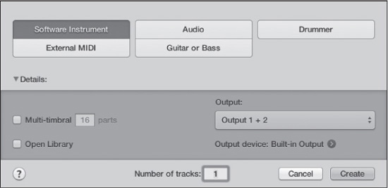
The software instrument track represents a simple MIDI device that plays on only one MIDI channel, but that produces audio via software instruments. To add software instrument tracks to your project, click the plus symbol at the top of the track list, select Track > New Software, or press Option+Command+N. Then click the Software Instrument button in the New Tracks dialog box that appears, as shown in Figure 3.4.
Figure 3.4 The New Tracks dialog box configured for creating new software instrument tracks.
© Apple Inc.
When you click the Software Instrument button, the New Tracks dialog box presents you with the following options:
![]() Multi-Timbral: Selecting the Multi-Timbral checkbox and entering a number in the Parts field creates your new software instrument as a multitimbral instrument with the number of parts you entered. Creating and using multitimbral software instruments is covered in Chapter 9, “Working with Software Instruments.”
Multi-Timbral: Selecting the Multi-Timbral checkbox and entering a number in the Parts field creates your new software instrument as a multitimbral instrument with the number of parts you entered. Creating and using multitimbral software instruments is covered in Chapter 9, “Working with Software Instruments.”
![]() Output: The Output menu allows you to assign your new software instrument tracks to specific hardware outputs or buses. If you select the Ascending option at the top of the Output menu, Logic will automatically assign hardware outputs or buses to your new software instrument tracks in ascending order.
Output: The Output menu allows you to assign your new software instrument tracks to specific hardware outputs or buses. If you select the Ascending option at the top of the Output menu, Logic will automatically assign hardware outputs or buses to your new software instrument tracks in ascending order.
![]() Open Library: Selecting the Open Library checkbox opens the Library in the main window when you create your new software instrument tracks, allowing you to instantly access channel-strip settings for your new software instrument channel strips. It also pre-loads the software instrument channel strips with an instrument and effects. Unless you know you want a lot of instances of Vintage Electric Piano in your template, it’s probably best to keep this option unchecked. Chapter 9 will teach you how to add software instruments to your software instrument channel strips.
Open Library: Selecting the Open Library checkbox opens the Library in the main window when you create your new software instrument tracks, allowing you to instantly access channel-strip settings for your new software instrument channel strips. It also pre-loads the software instrument channel strips with an instrument and effects. Unless you know you want a lot of instances of Vintage Electric Piano in your template, it’s probably best to keep this option unchecked. Chapter 9 will teach you how to add software instruments to your software instrument channel strips.
![]() Output Device: The Output Device field shows the currently selected output device for Logic. Clicking the right-arrow button to the right of the currently selected output device opens the Devices tab of the Audio Preferences window.
Output Device: The Output Device field shows the currently selected output device for Logic. Clicking the right-arrow button to the right of the currently selected output device opens the Devices tab of the Audio Preferences window.
After you configure the New Tracks dialog box to create your software instruments, click the Create button. The specified number of software instrument tracks will be created. Your new software instrument tracks will be visible in the main window, and channel strips for each new software instrument track will be added to the Mixer. Channel strips will also be created in the Mixer layer of the Environment for each new software instrument track.
If you need to create any more software instrument tracks, you can use any of the methods described earlier for creating more audio tracks, although the key command for creating a duplicate software instrument track is Option+Command+S.
Configuring the Software Instrument Track Inspector
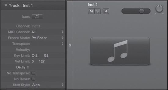
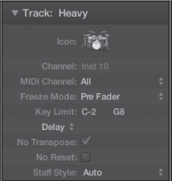
Because a software instrument track is a hybrid track that incorporates both MIDI sequencing capabilities and audio output, it has a wider range of track parameters than an audio track does. Figure 3.5 shows a newly created software instrument track and its Inspector.
Figure 3.5 A software instrument track with its Inspector.
© Apple Inc.
The software instrument track parameters are as follows:
![]() Track name: If you know what software instrument you are going to assign to a particular software instrument track, double-click on the default name to the right of the disclosure triangle—Inst 1 in Figure 3.5. Logic will display a text box in which you can type the new track name. For example, if you know you will be adding Sculpture to software instrument track 1 of your template, you could name software instrument track 1 “Sculpture.”
Track name: If you know what software instrument you are going to assign to a particular software instrument track, double-click on the default name to the right of the disclosure triangle—Inst 1 in Figure 3.5. Logic will display a text box in which you can type the new track name. For example, if you know you will be adding Sculpture to software instrument track 1 of your template, you could name software instrument track 1 “Sculpture.”
![]() Icon: Use this setting to select the icon you want to represent the software instrument track. If you know you’ll be dedicating a software instrument track to a specific software instrument, feel free to assign an icon to that software instrument track. If you click and hold the mouse pointer on the image, Logic will display a menu with categorized picture options. Find one that represents your software instrument in some way. For example, if the software instrument is Vintage Electric Piano, you can use an electric piano image; if it’s Ultrabeat, you could use one of the available drums options; and so on.)
Icon: Use this setting to select the icon you want to represent the software instrument track. If you know you’ll be dedicating a software instrument track to a specific software instrument, feel free to assign an icon to that software instrument track. If you click and hold the mouse pointer on the image, Logic will display a menu with categorized picture options. Find one that represents your software instrument in some way. For example, if the software instrument is Vintage Electric Piano, you can use an electric piano image; if it’s Ultrabeat, you could use one of the available drums options; and so on.)
![]() MIDI Channel: This parameter assigns the MIDI channel for your software instrument track. If you set the MIDI Channel parameter to All, then your software instrument will respond to any MIDI input when its track is selected. If you set the MIDI Channel parameter to a specific MIDI channel—channel 3, for example—then your software instrument will respond only to MIDI input on MIDI channel 3 when its channel is selected.
MIDI Channel: This parameter assigns the MIDI channel for your software instrument track. If you set the MIDI Channel parameter to All, then your software instrument will respond to any MIDI input when its track is selected. If you set the MIDI Channel parameter to a specific MIDI channel—channel 3, for example—then your software instrument will respond only to MIDI input on MIDI channel 3 when its channel is selected.
![]() Freeze Mode: The Freeze Mode parameter lets you specify whether the track will include effects in the resulting Freeze file if you freeze the track. The Freeze Mode parameter and Freeze tracks are covered in Chapter 6.
Freeze Mode: The Freeze Mode parameter lets you specify whether the track will include effects in the resulting Freeze file if you freeze the track. The Freeze Mode parameter and Freeze tracks are covered in Chapter 6.
![]() Transpose: If you enter a value here, every time you play this software instrument, Logic will automatically transpose the note it sends the software instrument up or down by the amount you specified. You can either double-click in the space to the right of Transpose to display a text box or drag the mouse pointer up or down to add or subtract up to 96 steps (a full eight octaves!) from the original value or half-step increments. If you click on the double-arrows to the right, you can quickly shift up to three octaves up or down.
Transpose: If you enter a value here, every time you play this software instrument, Logic will automatically transpose the note it sends the software instrument up or down by the amount you specified. You can either double-click in the space to the right of Transpose to display a text box or drag the mouse pointer up or down to add or subtract up to 96 steps (a full eight octaves!) from the original value or half-step increments. If you click on the double-arrows to the right, you can quickly shift up to three octaves up or down.
![]() Velocity: If you enter a value here, every time you play this software instrument, Logic will automatically increase or reduce the velocity of the MIDI note it sends to the software instrument by this value. You can double-click to the right of Velocity to display a text box or drag the mouse pointer up or down to increase or reduce the velocity of the MIDI note by up to 99 steps. (MIDI values are represented from 0 to 127, so this parameter can be used to adjust velocities through nearly the entire velocity range.)
Velocity: If you enter a value here, every time you play this software instrument, Logic will automatically increase or reduce the velocity of the MIDI note it sends to the software instrument by this value. You can double-click to the right of Velocity to display a text box or drag the mouse pointer up or down to increase or reduce the velocity of the MIDI note by up to 99 steps. (MIDI values are represented from 0 to 127, so this parameter can be used to adjust velocities through nearly the entire velocity range.)
![]() Key Limit: This parameter sets the upper- and lower-note boundaries of the software instrument. You can use this parameter to make certain that you do not send a software instrument a note outside of its range or to artificially reduce the range of the notes you choose to send a software instrument. For example, even though Vintage B3 Organ is capable of reproducing notes outside the actual range of a Hammond B-3, you might want to limit the notes to a Hammond’s real range to ensure a realistic organ sound. As with the previous two parameters, you can either double-click on the values to display a text box or click and hold on either value to use the mouse to raise or lower the value.
Key Limit: This parameter sets the upper- and lower-note boundaries of the software instrument. You can use this parameter to make certain that you do not send a software instrument a note outside of its range or to artificially reduce the range of the notes you choose to send a software instrument. For example, even though Vintage B3 Organ is capable of reproducing notes outside the actual range of a Hammond B-3, you might want to limit the notes to a Hammond’s real range to ensure a realistic organ sound. As with the previous two parameters, you can either double-click on the values to display a text box or click and hold on either value to use the mouse to raise or lower the value.
![]() Vel Limit: This parameter sets up the upper and lower velocity boundaries of the instrument. As with the previously discussed parameters, you can double-click on each value to display a text box or click and hold on the value to use the mouse to raise or lower the values.
Vel Limit: This parameter sets up the upper and lower velocity boundaries of the instrument. As with the previously discussed parameters, you can double-click on each value to display a text box or click and hold on the value to use the mouse to raise or lower the values.
![]() Delay: The term delay has many meanings in a musical (and even in a MIDI-related) context. In this context, it warrants further explanation. Basically, this Delay parameter allows you to send MIDI information to this software instrument either early or late, depending on the setting. This parameter is not a MIDI echo that enables you to create doubling or echo effects that are also often called delays. This parameter only adjusts the point at which Logic will commence sending data to your software instrument. Clicking on the arrows lets you select between delaying in ticks and delaying in milliseconds. You can double-click in the space to the right of Delay or click and hold the mouse pointer to raise or lower the value between –99 and +99 ticks or –500.0 and +500.0 ms, depending on your Delay value setting. (A tick is the smallest amount of distance possible on the main window’s Time ruler.)
Delay: The term delay has many meanings in a musical (and even in a MIDI-related) context. In this context, it warrants further explanation. Basically, this Delay parameter allows you to send MIDI information to this software instrument either early or late, depending on the setting. This parameter is not a MIDI echo that enables you to create doubling or echo effects that are also often called delays. This parameter only adjusts the point at which Logic will commence sending data to your software instrument. Clicking on the arrows lets you select between delaying in ticks and delaying in milliseconds. You can double-click in the space to the right of Delay or click and hold the mouse pointer to raise or lower the value between –99 and +99 ticks or –500.0 and +500.0 ms, depending on your Delay value setting. (A tick is the smallest amount of distance possible on the main window’s Time ruler.)
![]() No Transpose: If you select this checkbox, the software instrument is set to No Transpose. That means even if you are transposing all MIDI tracks globally or with the Transpose setting in the Region Inspector, the process will not affect this instrument. This checkbox is especially valuable for software instrument percussion tracks, where transposing notes often results in selecting completely different sounds.
No Transpose: If you select this checkbox, the software instrument is set to No Transpose. That means even if you are transposing all MIDI tracks globally or with the Transpose setting in the Region Inspector, the process will not affect this instrument. This checkbox is especially valuable for software instrument percussion tracks, where transposing notes often results in selecting completely different sounds.
![]() No Reset: If you select this checkbox, this software instrument will not respond to MIDI reset messages such as mod wheel and pitchbend resets, even if they are sent to all devices.
No Reset: If you select this checkbox, this software instrument will not respond to MIDI reset messages such as mod wheel and pitchbend resets, even if they are sent to all devices.
![]() Staff Style: This parameter is set to Auto by default. If you click and hold the arrows to the right of the parameter name, Logic displays a list of all the available default Score editor styles. In the Auto style, Logic picks an appropriate style based on the pitch range of the notes on the track. If you do not use the Score editor, you can ignore this parameter.
Staff Style: This parameter is set to Auto by default. If you click and hold the arrows to the right of the parameter name, Logic displays a list of all the available default Score editor styles. In the Auto style, Logic picks an appropriate style based on the pitch range of the notes on the track. If you do not use the Score editor, you can ignore this parameter.
Adding External MIDI Tracks
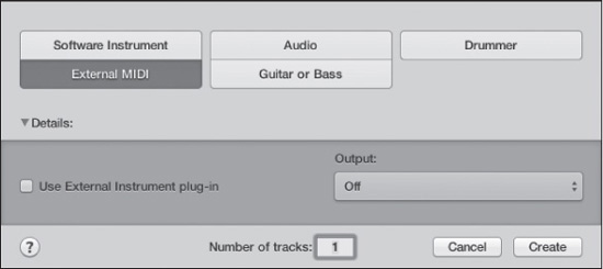
If you are planning to use external MIDI devices such as a MIDI keyboard as a sound source, or if you are planning to use ReWire to pipe audio into Logic, you need to use external MIDI tracks. To add external MIDI tracks to your project, click the plus symbol at the top of the track list, select Track > New, or press Option+Command+N. Then Click the External MIDI button. Figure 3.6 shows the New Tracks dialog box with the External MIDI button selected.
Figure 3.6 The New Tracks dialog box configured for creating new external MIDI tracks.
© Apple Inc.
As you can see in Figure 3.6, the only options available when you click the External MIDI button in the New Tracks dialog box are the Number of Tracks field, the Use External Instrument Plug-in checkbox, and an Output menu.
An external instrument is a software instrument that lets you merge the audio coming in from an external MIDI device with the MIDI that Logic sends to the external MIDI device on a single track. If you didn’t use the external instrument, you would need one external MIDI track for Logic to send MIDI information to the device and a separate audio track to get the external MIDI device’s audio back into Logic. External instruments are covered in Chapter 9.
The Output menu lets you select the MIDI OUT port and channel for the new external MIDI track. If you are creating multiple external MIDI tracks, select the Ascending option at the top of the Output menu, and Logic will automatically assign a new MIDI channel to each new external MIDI track ascending from the MIDI channel assigned in the Output menu. If you have multiple MIDI OUTs available, each OUT will have its own submenu giving you access to all the OUTs your MIDI interface offers. Working with MIDI ports is covered in more detail in the section “Setting Up Your MIDI Hardware” later in this chapter.
How many external MIDI tracks you should add depends on how many MIDI OUT ports your MIDI interface has or how many ReWire instruments you want to use. For each MIDI OUT you have, you can access 16 MIDI channels. It is very beneficial to have a dedicated MIDI connection for each of your external MIDI instruments, as this gives you access to all the power Logic offers for utilizing all your external MIDI hardware to the fullest. This is particularly true of multitimbral external MIDI equipment, which can allow you to access up to 16 MIDI channels simultaneously from one MIDI instrument.
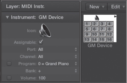
When you create a new external MIDI track, Logic creates a General MIDI multi-instrument object (GM device) in the Environment, as shown in Figure 3.7. Don’t worry that it’s a GM device; you can always reconfigure it for your specific piece of MIDI hardware, as you’ll see a little later in this chapter.
Figure 3.7 A General MIDI multi-instrument object in the Environment. When you create an external MIDI track, a multi-instrument object is automatically created in the Environment.

© Apple Inc.
Logic automatically creates a new GM device for each new set of 16 tracks. Note that the number of GM devices created depends on the number of MIDI OUT ports you have available on your MIDI interface. Therefore, if you have four MIDI OUT ports on your MIDI interface, you can create up to 64 external MIDI tracks in the New Tracks dialog box and have four GM devices automatically added to the Environment. You can always add more instrument objects and GM devices in the Environment later if need be. To add duplicate external MIDI tracks, use the Track > New External MIDI command or press Option+Command+X.
Setting Up the GM Device
A multitimbral instrument is an instrument that can play sounds on up to 16 MIDI channels simultaneously. When you first create new external MIDI tracks, you should open an Environment window (Command+0) and configure the GM device that communicates with your multitimbral instrument. Click the downward-pointing triangle button in the upper-left corner of the Environment window to open the Layer menu; then choose the MIDI Instr. layer to view your GM device(s) and the Inspector shown in Figure 3.8.
Figure 3.8 A software instrument track with its Inspector.
© Apple Inc.
The functions of the parameters in the GM Device Inspector are as follows:
![]() Instrument name: To give your new multi instrument a name, click on the word (GM Device) to the right of the disclosure triangle. Logic will display a text box in which you can type the new name.
Instrument name: To give your new multi instrument a name, click on the word (GM Device) to the right of the disclosure triangle. Logic will display a text box in which you can type the new name.
![]() Icon: The added visual cue of an icon can help you visualize your device. You might as well take care of assigning one while configuring your GM device. Selecting an icon was discussed earlier, in the section “Configuring the Software Instrument Track Inspector.”
Icon: The added visual cue of an icon can help you visualize your device. You might as well take care of assigning one while configuring your GM device. Selecting an icon was discussed earlier, in the section “Configuring the Software Instrument Track Inspector.”
![]() Port: You’ll want to make sure your instrument is set to the correct port. Click the number (or it might be the word “All,” as in Figure 3.8) next to the Port parameter, and you’ll see a list of all available MIDI ports. Choose the one to which your device is connected. MIDI ports are covered in more detail later in this chapter, in the section “Selecting MIDI Ports.”
Port: You’ll want to make sure your instrument is set to the correct port. Click the number (or it might be the word “All,” as in Figure 3.8) next to the Port parameter, and you’ll see a list of all available MIDI ports. Choose the one to which your device is connected. MIDI ports are covered in more detail later in this chapter, in the section “Selecting MIDI Ports.”
![]() Channel: If your device is capable of operating on only a single MIDI channel, or if your instrument represents only a single patch on a synth, be sure to select that channel in the Channel parameter. Click the number next to Channel and select the proper MIDI channel, from 1 to 16. If you want the notes in your MIDI regions to determine the MIDI channel, set the Channel parameter to All.
Channel: If your device is capable of operating on only a single MIDI channel, or if your instrument represents only a single patch on a synth, be sure to select that channel in the Channel parameter. Click the number next to Channel and select the proper MIDI channel, from 1 to 16. If you want the notes in your MIDI regions to determine the MIDI channel, set the Channel parameter to All.
![]() Program: Select this checkbox and select a program number between 0 and 127 if you want this instrument to always select a specific patch in your MIDI device.
Program: Select this checkbox and select a program number between 0 and 127 if you want this instrument to always select a specific patch in your MIDI device.
![]() Bank: Most modern MIDI devices include several banks of sounds, generally at 128 presets per bank. If your MIDI device recognizes bank select messages, you can use the Bank parameter to send the desired message to access the desired preset on your MIDI device.
Bank: Most modern MIDI devices include several banks of sounds, generally at 128 presets per bank. If your MIDI device recognizes bank select messages, you can use the Bank parameter to send the desired message to access the desired preset on your MIDI device.
![]() Volume: Select this checkbox and select a MIDI volume level between 0 and 127 if you want this instrument to always set your MIDI device to a specific volume.
Volume: Select this checkbox and select a MIDI volume level between 0 and 127 if you want this instrument to always set your MIDI device to a specific volume.
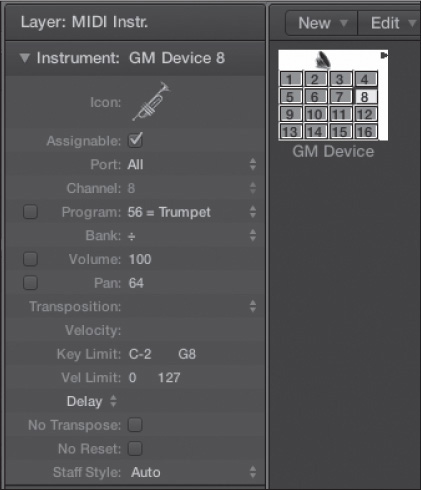
After you have set parameters for the GM device as a whole, it’s time to activate its individual subchannels. If any boxes in the GM device have lines through them, it’s because those subchannels are turned off by default. You’ll want to activate as many subchannels as your instrument supports. For example, if your synth is eight-part multitimbral, you’ll activate eight subchannels in the multi instrument by clicking on them. Figure 3.9 shows the GM device with all channels activated.
Figure 3.9 A GM device with all subchannels activated. The Inspector shown is the unique Inspector for subchannel 8.
© Apple Inc.
Notice that each subchannel has its own on/off toggle and associated Inspector. Most of the parameters you see in the Inspector are identical to those in the software instrument Track Inspector previously discussed, and they function identically. Additionally, each GM device channel has Program and Bank parameters for loading specific presets per MIDI channel. There’s also a Pan parameter for setting a panorama placement for each channel via MIDI. Because each subchannel of a GM device is basically a unique single-channel MIDI instrument, you get a set of six general parameters for the entire MIDI instrument, but you might want each subchannel to be completely unique. If you already know how you want to set up your subchannels, go ahead and set the Inspectors as you activate the channels. Be careful about setting a global port value, however, because it applies to the entire multi instrument.
The Multi Instrument Window
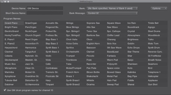
The other window that you can access from a GM device is the Multi Instrument window. If you double-click any GM device, Logic displays this window, shown in Figure 3.10. Here you can set up the banks and patch names of your GM device.
You can set several parameters in this window:
![]() Device Name and Short Device Name: The device name is simply the name of your multi-instrument object. You should have already named your multi instrument, and that name should already appear in the Device Name box. In the Short Device Name box, you can type a short abbreviation of the instrument name that will appear in the main window track list when a multi instrument’s program name is also being displayed.
Device Name and Short Device Name: The device name is simply the name of your multi-instrument object. You should have already named your multi instrument, and that name should already appear in the Device Name box. In the Short Device Name box, you can type a short abbreviation of the instrument name that will appear in the main window track list when a multi instrument’s program name is also being displayed.
![]() Bank: This menu enables you to select among banks of patches on your MIDI device. Each multi-instrument object allows up to 15 banks, numbered 0–14. If you choose Bank 1–14, Logic asks whether you want to initialize the bank. If you want to enter your own bank names, press Return. If you want to use the generic General MIDI names, starting with Bank 0, click Cancel. In general, unless your instrument is specifically a General MIDI device, you’ll want to enter your own names (See the upcoming “Program Names” entry in this list).
Bank: This menu enables you to select among banks of patches on your MIDI device. Each multi-instrument object allows up to 15 banks, numbered 0–14. If you choose Bank 1–14, Logic asks whether you want to initialize the bank. If you want to enter your own bank names, press Return. If you want to use the generic General MIDI names, starting with Bank 0, click Cancel. In general, unless your instrument is specifically a General MIDI device, you’ll want to enter your own names (See the upcoming “Program Names” entry in this list).
![]() Bank Message: This menu allows you to select among different MIDI messages that will be sent to your MIDI device when you switch banks. Different manufacturers and devices use different messages to switch banks, so you need to consult your MIDI device’s documentation to see which selection is appropriate for each device.
Bank Message: This menu allows you to select among different MIDI messages that will be sent to your MIDI device when you switch banks. Different manufacturers and devices use different messages to switch banks, so you need to consult your MIDI device’s documentation to see which selection is appropriate for each device.
Figure 3.10 The Multi Instrument window for a multi-instrument object.
© Apple Inc.
![]() Program Names: You’ll notice that 128 program names are visible in the Multi Instrument window for each bank. You can enter the specific names for the various programs of your device here. You can do this in a number of ways:
Program Names: You’ll notice that 128 program names are visible in the Multi Instrument window for each bank. You can enter the specific names for the various programs of your device here. You can do this in a number of ways:
![]() Double-click on each program name one by one and manually type the new program name in the text boxes that appear.
Double-click on each program name one by one and manually type the new program name in the text boxes that appear.
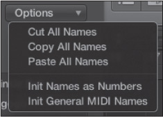
![]() Copy data from the Clipboard by using the Options menu to the right of the Bank Message menu (see Figure 3.11). You can easily type the program numbers and names into a word-processing program and simply use the menu to copy them all to the correct program. You can also copy and paste program names from another multi-instrument object by using either this menu or the Copy and Paste global commands. If the device’s manufacturer has a preset list in PDF format, you may also be able to copy and paste it in from the PDF, perhaps after a little editing in a word processor.
Copy data from the Clipboard by using the Options menu to the right of the Bank Message menu (see Figure 3.11). You can easily type the program numbers and names into a word-processing program and simply use the menu to copy them all to the correct program. You can also copy and paste program names from another multi-instrument object by using either this menu or the Copy and Paste global commands. If the device’s manufacturer has a preset list in PDF format, you may also be able to copy and paste it in from the PDF, perhaps after a little editing in a word processor.
Figure 3.11 The Options menu in the Multi Instrument window.
© Apple Inc.
![]() If you want program numbers instead of names, select Options > Init Names as Numbers.
If you want program numbers instead of names, select Options > Init Names as Numbers.
![]() If you wish to use General MIDI program names, select Options > Init General MIDI Names.
If you wish to use General MIDI program names, select Options > Init General MIDI Names.
![]() Use GM Drum Program Names for Channel 10: In General MIDI devices, channel 10 is reserved for drums. The General MIDI drum kit also contains a standard set of drum kits. If you select this checkbox, Logic automatically uses the standard drum set names for subchannel 10.
Use GM Drum Program Names for Channel 10: In General MIDI devices, channel 10 is reserved for drums. The General MIDI drum kit also contains a standard set of drum kits. If you select this checkbox, Logic automatically uses the standard drum set names for subchannel 10.
Once you have configured all your GM devices, you can easily reassign external MIDI tracks to different MIDI devices and different MIDI channels in those devices using the Library in the main window. Simply open the Library by clicking the Library button in the control bar and browse the different folders that represent your GM devices.
TIP: The best part about customizing the program names for your GM devices is that if you select the GM device in a track in the main window and your track header has enough room, it will display the actual track name. Also, if you have the Program button (one of the performance parameters in the instrument Track Inspector mentioned but not detailed earlier) checked for that subchannel, you can send your device program changes from the main window by clicking on program names (and scroll through your synth’s programs by scrolling through the program names in the main window). Because you have all the names typed in, you can send changes by name rather than by number. For this reason, even for mono synths that are not multitimbral, you should seriously consider using a GM device for the MIDI device and only activating one subchannel. This might seem like overkill, but it conveniently enables you to customize patch names, which is worth the minimal additional effort.
Adding Drummer Tracks
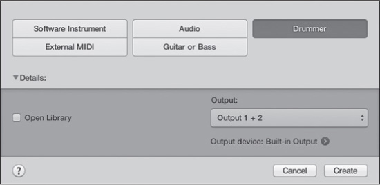
Drummer is one of the major new features in Logic Pro X, and a really cool one to boot. Drummer gives you access to a highly configurable, specialized instrument and track that include detailed drum samples of a number of different kits in several styles with automatically generated drum parts. To add a Drummer track, click the plus symbol at the top of the track list, select Track > New, or press Option+Command+N. Then click the Drummer button. Figure 3.12 shows the New Tracks dialog box with the Drummer button selected.
Figure 3.12 The Drummer options in the New Tracks dialog box.
© Apple Inc.
The options in the New Drummer dialog box are familiar. Selecting the Open Library checkbox opens the Library in the main window after you create the new Drummer track, letting you browse the different drum kits. The Output menu lets you select the hardware outputs for your Drummer track. The Output Device field displays the currently selected output device, and the right-arrow button gives you access to the Devices tab of the Audio Preferences window.
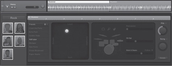
Drummer is similar to a software instrument, but it automatically adds regions to the Drummer track when you click Create. Drummer’s specialized editor also opens when you create a new Drummer track. Figure 3.13 shows a Drummer track with its specialized regions and editor.
Configuring the Drummer Track Inspector
The Drummer Track Inspector is basically a stripped-down version of the software instrument Track Inspector, with the options in the Drummer Track Inspector functioning identically to the same options in the software instrument Track Inspector. Figure 3.14 shows the Drummer Track Inspector.
Figure 3.13 A Drummer track and the Drummer editor.
© Apple Inc.
Figure 3.14 The Drummer Track Inspector offers many of the same options as the software instrument Track Inspector.
© Apple Inc.
If you’re planning to do a lot of writing in Logic or are otherwise hoping to use real drum sounds in your projects, but won’t always have access to a real drummer or simply won’t have the capabilities to record a real drummer, having Drummer ready to go in your template is an excellent idea. Because Drummer is such a major new feature in Logic, and because it involves many different aspects of the main window, I’ll dive deeper into Drummer and its capabilities in Chapter 6.
Adding ReWire Tracks
Although adding and configuring ReWire tracks is covered in detail in Chapter 9, if you know you will be using a ReWire slave with Logic, you may want to add some ReWire tracks to your template project.
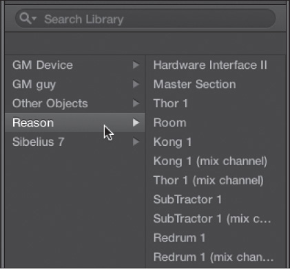
To add ReWire tracks to your project, you need to create some new—or configure some existing—external MIDI tracks. To configure your external MIDI tracks for ReWire use, select the external MIDI track you wish to configure. Then launch the desired ReWire application. Once the ReWire application has launched, you can access any available ReWire instruments in the Library, as shown in Figure 3.15, and assign a ReWire instrument to your selected external MIDI track.
Figure 3.15 You can use the Library to assign the instruments available in your ReWire applications to external MIDI tracks.
© Apple Inc.
After you have configured your external MIDI tracks for ReWire transmission, you can play and sequence the instruments in your ReWire applications from Logic. To route the audio from your ReWire applications into Logic, you will need to create and configure auxiliary channel strips. Creating auxiliary channel strips is covered in the next section of this chapter. Configuring auxiliary channel strips for ReWire audio transmission is covered in detail in Chapter 9. Note that your ReWire slave has to run in 64-bit mode for Logic to access it.
Adding Auxiliary Tracks
Auxiliary channel strips, or aux channel strips, are destinations for buses in Logic. For those unfamiliar with auxes and buses, they are covered in Chapter 11. Briefly, a bus is used to transmit audio from one or more channel strips to another channel strip in Logic. An aux is the most common destination for a bus. One common use of an aux channel strip is to instantiate a reverb effect in the aux channel strip and to send audio from a variety of audio or software instrument tracks through a bus to the aux, allowing them all to utilize the same reverb effect. If you are familiar with auxes and buses, or you think you can see the value of having a few auxes in your template, then you may want to add a few to your template.
Creating Auxiliary Channel Strips
To create a new aux, open the Mixer either in the main window by clicking the X button or in a Mixer window by selecting Window > Mixer or by pressing Command+2. From the Mixer’s local Options menu, select Create New Auxiliary Channel Strips; alternatively, press Control+N. This will create a new auxiliary channel strip. You can create more auxes via the Create New Auxiliary Channel Strips command.
NOTE: When I say Mixer, that’s exactly what I mean: the separate window called Mixer or the Mixer that’s integrated in the main window. I do not mean the Mixer layer of the Environment. If you think you opened the Mixer window but you see the Layer menu, make sure you didn’t open the Environment Mixer! For more on this distinction, check out Chapter 11.
Adding Auxiliary Tracks to the Main Window
Now that you have created some aux channel strips, you can add auxiliary tracks to the Tracks area in the main window. Having auxiliary tracks in the main window can be valuable because it enables you to easily automate and edit the automations for a wide variety of aux channel strip parameters and insert effect parameters, as you’ll explore in Chapter 10, “Using Automation in Logic.”
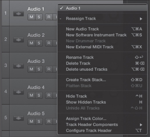
In the Tracks area, create a new track for each aux you would like to have in the main window. It doesn’t matter what type of tracks you create because you will be reassigning them. To reassign a track to an aux, follow these steps:
1. Right-click on the selected track header. This will open the menu shown in Figure 3.16.
Figure 3.16 Right-clicking on a track header opens this menu.
© Apple Inc.
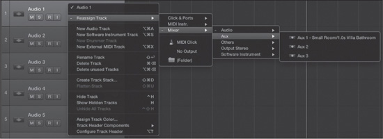
2. Choose Reassign Track > Mixer > Aux and select the aux channel strip you want to assign to the current track, as shown in Figure 3.17.
Figure 3.17 To reassign a track to an auxiliary track, choose Reassign Track > Mixer > Aux and select the aux you wish to assign to the track.
© Apple Inc.
Setting Up Your Main Window
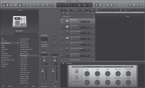
We’ve spent quite a few pages discussing the basic setup of your template project, but no less important is setting up the main window. For example, Figure 3.18 contains the main window generated by the Electronic template from the Project Chooser.
Figure 3.18 An example of a main window generated by the Electronic template. Most likely, you will prefer a different configuration for your own personalized template.
© Apple Inc.
Does this look like your ideal workspace? Or do you imagine yourself using a different combination of tracks—perhaps with different instrument names? Do you want your track lanes to have more room? The main windows in the provided templates are designed to offer users a sampling of available track types and configurations, in the hopes that some of what they need might be included in a particular template. For your template, you want your main window to represent your personal working needs.
TIP: As you can see, using key commands in Logic is a major timesaver. Creating tracks isn’t fun, creative work—it’s an administrative task that most people just want to finish as soon as they can. If you are creating 50 or more tracks of different types using menus, that means you have to navigate to the menu option, then re-navigate to the menu option, then re-navigate to the menu option. If you use the key command, however, creating each new track is as rapid as tap, tap, tap! I’ll continue to show you the menu options as well as the default key commands throughout this book, but you should commit some time to learning to use Logic via the key commands. Now is an excellent time to start!
Setting Up Tracks
Although many of the steps involved in creating your tracks are simplified and streamlined in Logic, there are still a few more things you may want to set up to finish configuring your template.
Naming Tracks
Now that you’ve created as many tracks as you think you’ll need, you might want to think about giving them slightly more descriptive names than simply audio 1, audio 2, and so on. Of course, you probably don’t know what your final track names will be, but perhaps you expect you will need 12 separate audio tracks for your drums, for example. If so, you might rename audio 24–36 (or whichever tracks you choose) drums 1–12. Did you only need eight MIDI tracks divided between two separate MIDI synths, such as a Roland and a Korg synth? Why not name the MIDI tracks Korg 1–Korg 4 and Roland 1–Roland 4 to be more descriptive? Remember, customizing your main window to be your personal workspace is the name of the game!
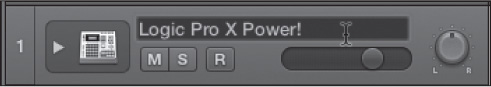
The easiest way to name tracks is to click the track name in the Track Inspector or to double-click the name in the track header. As soon as you do, a text box will appear with the current name of the track highlighted, as shown in Figure 3.19. Type any name you want, then press Return, press Esc, or click anywhere outside the text box.
Figure 3.19 To rename a track in your track list, click the track name next to the triangle in that track’s Inspector or double-click the track name in the track header as shown. When the text box appears, type the new name.
© Apple Inc.
You can also use a menu command to name tracks—Track > Rename Track—or press Shift+Return. If you change track names using the menu command, you are actually naming the track itself. By default, this distinction makes no difference; however, if you decide to display the additional names of your tracks by selecting the checkbox in the Additional Name Column section of the Track Header Configuration dialog box, you can configure Logic to display not only the track name or the name created with the Rename Track command, but a variety of different name types for either the first or second track name. To open the Track Header Configuration dialog box, do one of the following:
![]() Select Track > Configure Track Header.
Select Track > Configure Track Header.
![]() Right-click on the track header and select Configure Track Header from the menu that appears.
Right-click on the track header and select Configure Track Header from the menu that appears.
![]() Press Option+T.
Press Option+T.
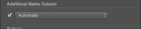
Figure 3.20 shows the Additional Name Column section of the Track Configuration dialog box.
Figure 3.20 The Additional Name Column section of the Track Header Configuration dialog box. Selecting the checkbox displays the second names of your tracks.
© Apple Inc.
The menu in the Additional Name Column section of the Track Header Configuration dialog box offers these options:
![]() Automatic: This option names your tracks based on the following criteria, in order: user-entered names, channel-strip settings or software instrument names, and in the absence of one of the previous options, the parent channel strip’s name.
Automatic: This option names your tracks based on the following criteria, in order: user-entered names, channel-strip settings or software instrument names, and in the absence of one of the previous options, the parent channel strip’s name.
![]() Patch or Channel Strip Setting Name: This option displays the patch or channel strip setting name for the parent channel strip of each track. A channel strip’s setting involves only a single channel strip. A patch can include aux channel strips and Smart Controls, and even Track Stacks. You’ll look at channel strip settings and patches in more detail in Chapter 11.
Patch or Channel Strip Setting Name: This option displays the patch or channel strip setting name for the parent channel strip of each track. A channel strip’s setting involves only a single channel strip. A patch can include aux channel strips and Smart Controls, and even Track Stacks. You’ll look at channel strip settings and patches in more detail in Chapter 11.
![]() Software Instrument Setting Name: This option displays the software instrument setting name for each software instrument track.
Software Instrument Setting Name: This option displays the software instrument setting name for each software instrument track.
![]() Channel Strip Name: This option displays the channel strip name of each track’s parent channel strip in the Mixer.
Channel Strip Name: This option displays the channel strip name of each track’s parent channel strip in the Mixer.
![]() Channel Strip Type and Number: This option displays the type and number of each track’s parent channel strip. For example, if a track’s parent channel strip is the third auxiliary channel strip, the track’s name will be aux 3.
Channel Strip Type and Number: This option displays the type and number of each track’s parent channel strip. For example, if a track’s parent channel strip is the third auxiliary channel strip, the track’s name will be aux 3.
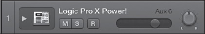
When you enable the additional name, the additional name is displayed over the Volume slider in the track header. Thus, you could have a track named Nord Electro on a track named Wurly, for example, or a track named Ambient Guitar on a track named audio 6. Figure 3.21 shows a track with this view enabled.
Figure 3.21 If you have chosen to display additional names in the track header, you’ll see the additional name you designated in the menu found in the Additional Name Column section of the Track Header Configuration dialog box.
© Apple Inc.
You can also access the Additional Name Column options by right-clicking on the track header, selecting Track Header Components > Additional Name Column, and choosing one of the Additional Name Column options.
NOTE: For ages, Logic had fairly unintuitive track and channel-strip naming practices. Naming a track didn’t name its channel strip, and naming a channel strip didn’t name its track. It was often a confusing mess getting your Arrange window (the old name of the main window) and your Mixer names unified. Since the introduction of Logic Pro 9, you can easily name your tracks in the main window using the track header, the Track Inspector, or the selected track’s main window channel strip; in the Mixer; or in the Environment Mixer layer. The name of a track is unified across the entire application!
Coloring Tracks
As a final method of customizing your template tracks, you might want to think about coloring them. Certainly it won’t affect your music or creativity in any way if you do or do not use a unique color for each track, but it does help to keep tracks separate and to visually group tracks that you want to keep together, such as tracks for the same MIDI instrument or for similar types of audio recordings. For example, you might color all your drum tracks the same color.
First, to see the colors you are choosing before each track lane has any regions on it, make sure Track Color Bars is selected in the Track Header Configuration menu. To access the Track Header Configuration menu (covered in full detail in Chapter 6), right-click in any track’s track header or press Option+T. Alternatively, select Track Header Components > Show Track Color Bars in the right-click track header menu. With Track Color Bars selected, you will see a small line at the left of each track header that shows you the color for that track. To change the color, display the Color palette by doing one of the following:
![]() Selecting View > Show Colors
Selecting View > Show Colors
![]() Selecting Track > Assign Track Color
Selecting Track > Assign Track Color
![]() Choosing Assign Track Color in the track header right-click menu
Choosing Assign Track Color in the track header right-click menu
![]() Pressing Option+C.
Pressing Option+C.
Logic presents its Color palette, as shown in Figure 3.22. When you click on any of the palette’s colors, you will see the line of color change to the selected color.
Figure 3.22 Logic’s Color palette. Click on a color to choose it for the selected track in the main window.

© Apple Inc.
Configuring the Initial Zoom and Automation Settings
You may want all of your track lanes to be wider or thinner than the default tracks that Logic creates in the main window. Basically, the skinnier the track lane, the more tracks will fit in the track list—but the less detail you will see for each track. You may also want the horizontal zoom in the Tracks area to be more zoomed in (for more precise detail) or more zoomed out (for an overview of an entire song).
Many Logic users choose to set up an initial screenset with a main window with wider track lanes and a tight horizontal zoom to focus on a specific group of tracks, and then another screenset with a main window with very skinny track lanes horizontally zoomed out for viewing the whole song at once.
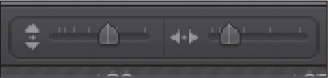
To accomplish this, you can use the zoom sliders at the upper-right corner of the Tracks area (see Figure 3.23). The slider on the left controls vertical zoom. Dragging the slider to the right increases the track lane height, and dragging the slider to the left decreases the track lane height. The slider on the right controls horizontal zoom. Dragging the slider left decreases how much horizontal space is shown between each bar/SMPTE location, and dragging the slider right increases how much horizontal space is shown between each bar/SMPTE location. You can also use the zoom key command, Control+arrow. Press the appropriate arrow key, depending on whether you are increasing (up) or decreasing (down) the vertical zoom or increasing (right) or decreasing (left) the horizontal zoom.
Figure 3.23 The vertical and horizontal zoom sliders allow you to adjust vertical and horizontal zoom for the entire Tracks area.
© Apple Inc.
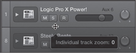
Logic also offers a number of ways to vertically resize individual tracks without resizing the other tracks in the Tracks area. If you move the mouse pointer to the bottom edge of a track header, the cursor will turn into a resize cursor, as shown in Figure 3.24. The resize cursor lets you click and drag the mouse vertically to increase or decrease the height of that individual track. A help tag opens to show you a numeric value for your individual track zoom setting, also shown in Figure 3.24. You can also select a track and use the key commands for Individual Track Zoom In (Control+Option+Command+up arrow) and Individual Track Zoom Out (Control+Option+Command+down arrow). Finally, you can activate the Auto Track Zoom feature in the local Tracks area View menu or by pressing Control+Z. Auto Track Zoom will increase the size of whichever track in the Tracks area you have currently selected, leaving all unselected tracks at their normal height.
Figure 3.24 If you move the cursor to the bottom of a track header, the cursor will turn into a resize cursor, indicating that you can adjust the height of the track by dragging up or down with your mouse. A help tag opens, giving a numeric value for the size of the track.
© Apple Inc.
Setting Up Screensets
We’ve already discussed screensets, which are one of Logic’s indispensable customization tools. Using screensets, you can set up each view in Logic to have its own unique set of editors and windows, and you can easily switch between the views by using the number keys. Press a number key or two to get a quick glimpse at what screensets can do for you. It’s kind of like having multiple workflows or templates within your projects.
Setting up screensets couldn’t be simpler: You simply press a number key to go to a screenset and organize the various windows and editors as you like. Then, when you save your template project, all your screensets will be automatically saved as well. No muss, no fuss! There are only a couple of special options for creating screensets that you might want to consider using, and they are discussed in this section.
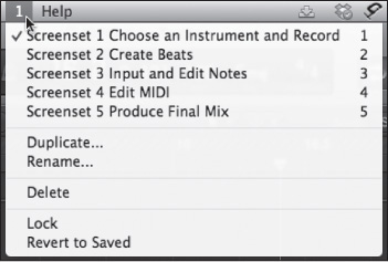
First, if you open the Screenset menu (the number displayed between the Window and the Help menus), you’ll notice a list of current screensets and, below that, a menu of screenset options. You can see this in Figure 3.25, which shows the screensets of the Electronic template.
Figure 3.25 The Screenset menu displays a list of your screensets plus screenset options.
© Apple Inc.
The screenset options are as follows:
![]() Duplicate: If you want to create a new screenset using the current screenset as a base, select Duplicate. This opens the Duplicate Screenset dialog box, where you can assign the duplicate screenset to the number of your choice and name the screenset.
Duplicate: If you want to create a new screenset using the current screenset as a base, select Duplicate. This opens the Duplicate Screenset dialog box, where you can assign the duplicate screenset to the number of your choice and name the screenset.
![]() Rename: Selecting the Rename option opens the Rename Screenset dialog box, where you can rename your screenset.
Rename: Selecting the Rename option opens the Rename Screenset dialog box, where you can rename your screenset.
![]() Delete: You can use the Delete command to delete the current screenset. Be advised that there is no warning dialog box when you use this command.
Delete: You can use the Delete command to delete the current screenset. Be advised that there is no warning dialog box when you use this command.
![]() Lock: If you know that, even if you open and close windows while using Logic, you’ll want the windows of a particular screenset to never change from Logic session to Logic session, you can choose to lock the screenset using the Lock menu command.
Lock: If you know that, even if you open and close windows while using Logic, you’ll want the windows of a particular screenset to never change from Logic session to Logic session, you can choose to lock the screenset using the Lock menu command.
![]() Revert to Saved: The Revert to Saved command simply returns the current screenset to its original state, just like you used the key command for selecting that particular screenset.
Revert to Saved: The Revert to Saved command simply returns the current screenset to its original state, just like you used the key command for selecting that particular screenset.
Setting up your screensets in your template is really this easy! Trust me—using screensets is one of the best ways to configure Logic to reflect how you want to work.
Defining Key Commands
Don’t worry. You’re not going to give every command in Logic a key command at this point. But as you work on your template, you should begin to get a feel for which commands you might like to access from the keyboard instead of the menus so you can begin defining your own key commands. Logic makes this process simple with its extremely powerful and intuitive Key Commands window. To access the Key Commands window (see Figure 3.26), select Logic Pro > Preferences > Key Commands or press Option+K.
You will notice that the key commands are grouped into commands relating to specific windows and editors in the Command list. You can click any of the disclosure triangles from any or all of the groups to see what key commands are available for that window or editor.
Figure 3.26 The Key Commands window offers many different methods to search for and assign key commands.
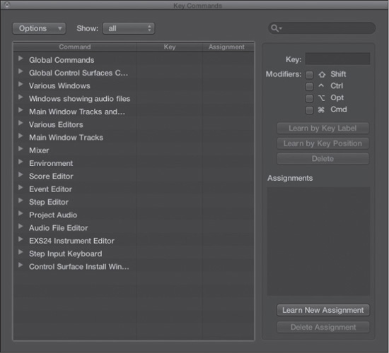
© Apple Inc.
The easiest way to define a key command is simply to search for the command and then inform Logic as to which key you wish to use as the key command. For example, suppose you want to assign a key command to the Duplicate Screenset command. In that case, do the following:
1. Type the word screenset in the Search field in the Key Commands window, as shown in Figure 3.27. Logic will display a list of all key commands with the word “screenset” in their name.
2. When you have found the correct command, select it. In this example, select the Duplicate Screenset command.
3. Assign a key to a command by doing one of the following.
![]() Click the Learn by Key Label button: This “learns” key sequences based on the label of the key you press. In other words, if you press a key labeled 3, then 3 will be assigned to that command. In this example, click the Learn by Key Label button, then press Command+Shift+2. You will see the Key field and Modifiers boxes reflect your choice, as shown in Figure 3.28. You can now press Command+Shift+2 (the 2 on either the keyboard or the numeric keypad) to lock or unlock a screenset. Your new key command is listed in the Key column of the Command list. Make sure you disengage the Learn by Key Label button before you press any other keys!
Click the Learn by Key Label button: This “learns” key sequences based on the label of the key you press. In other words, if you press a key labeled 3, then 3 will be assigned to that command. In this example, click the Learn by Key Label button, then press Command+Shift+2. You will see the Key field and Modifiers boxes reflect your choice, as shown in Figure 3.28. You can now press Command+Shift+2 (the 2 on either the keyboard or the numeric keypad) to lock or unlock a screenset. Your new key command is listed in the Key column of the Command list. Make sure you disengage the Learn by Key Label button before you press any other keys!
Figure 3.27 To search for key commands, type a search word into the Search field of the Key Commands window.

© Apple Inc.
Figure 3.28 If you click the Learn by Key Label button and then press Command+Shift+2, the Key field and Modifiers boxes will reflect your choice.
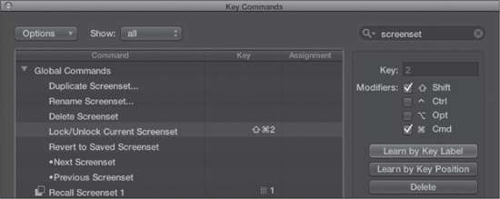
© Apple Inc.
![]() Click the Learn by Key Position button: This key command option allows you to assign a key command not based on the label on the key, but based on the position of the key on the keyboard. The advantage of this is that you can assign different key commands to the number 2 above the keyboard and the number 2 in the numeric keypad. It also means that if you switch between different languages, your key assignments will remain the same. Using the same example, if you click the Learn by Key Position button and press Command+Shift+2, the Key Assignment field will reflect the location code (or scan code) of the key pressed (in this case, the number 2 above the keyboard, not the numeric keypad), and only those exact keys will be assigned to the command, as shown in Figure 3.29. Your new key command is listed in the Key column of the Command list.
Click the Learn by Key Position button: This key command option allows you to assign a key command not based on the label on the key, but based on the position of the key on the keyboard. The advantage of this is that you can assign different key commands to the number 2 above the keyboard and the number 2 in the numeric keypad. It also means that if you switch between different languages, your key assignments will remain the same. Using the same example, if you click the Learn by Key Position button and press Command+Shift+2, the Key Assignment field will reflect the location code (or scan code) of the key pressed (in this case, the number 2 above the keyboard, not the numeric keypad), and only those exact keys will be assigned to the command, as shown in Figure 3.29. Your new key command is listed in the Key column of the Command list.
Figure 3.29 Learn by Key Position memorizes the specific keys you have pressed and assigns that sequence to your key command—in this case, Command+Shift+2 (above the keyboard, not on the numeric keypad).
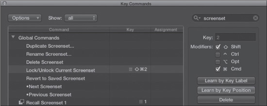
© Apple Inc.
![]() Click the Learn New Assignment button: If you want to assign a command to a control surface, click this button, then move or press the control on the control surface to which you wish to assign this command. The Assignments pane will reflect what you moved or pressed, as shown in Figure 3.30.
Click the Learn New Assignment button: If you want to assign a command to a control surface, click this button, then move or press the control on the control surface to which you wish to assign this command. The Assignments pane will reflect what you moved or pressed, as shown in Figure 3.30.
That’s it! You’ve just activated a new key command! As you become more familiar with Logic, you will use these methods not only to activate key commands that do not have defaults, but also to assign different key commands than the Logic default key sequences to better suit your own working methods.
NOTE: If you are unfamiliar with Logic’s key commands and want to get in the habit of using them, a great way to learn key commands is to make yourself a cheat sheet of your most-used key commands and leave it right next to your keyboard. This can be an index card, a sheet of paper, or any other material that works for you. You can also select Show > Used in the Key Commands window, then select Options > Copy Key Commands to Clipboard, and finally paste the list into a word processor for printout. Use cheat sheets to help familiarize yourself with key commands until they become second nature to you!
Figure 3.30 You can assign key commands to control surfaces as well as keyboards and MIDI devices by using the Learn New Assignment button.
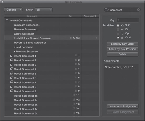
© Apple Inc.
Setting Up Your Hardware
These days, there are many options for hardware that can interface with a DAW, and having Logic configured to work with your hardware is essential to ensuring the kind of ease of use that keeps inspiration flowing when it hits. Before you finalize your initial setup of Logic, you need to look at configuring your audio interface, your MIDI gear, and any control surfaces you may be using.
Interfaces and Drivers
Sometimes, simply plugging your audio interface into your computer is enough to enable your computer to recognize the interface so that you can start using it. Other times, the audio interface comes with drivers—files that explain to your computer how to communicate with your interface. For example, with Mac OS X, audio and MIDI interfaces that support the standard USB, FireWire, or Thunderbolt class–compliant drivers that are built into Core Audio (explained in the next section) and Core MIDI do not require additional drivers, whereas all other audio and MIDI devices require installation of manufacturer-supplied drivers. If your hardware requires manufacturer-supplied drivers, you may need to make sure they offer 64-bit bit drivers.
In general, most of the configuration of audio and MIDI devices is done inside Logic, so driver installation is usually a very straightforward process of inserting the CD that came with your hardware or (more likely) downloading drivers from the Internet, and then launching an installation application. Most device-driver installations require you to restart your computer at the end of the process because most operating systems scan for new drivers only when the system starts up.
Configuring Your Audio Device
To get the most out of your system, you will need to tell Logic exactly how you want to use your hardware. You can configure how Logic will interact with your audio interface in the Devices tab of the Audio Preferences window, which you can access by choosing Logic Pro X > Preferences > Audio and then clicking on the Devices tab. The Devices tab of the Audio Preferences window is shown in Figure 3.31.
Figure 3.31 The Devices tab of the Audio Preferences window. Here you can configure how you want Logic to use your audio device.
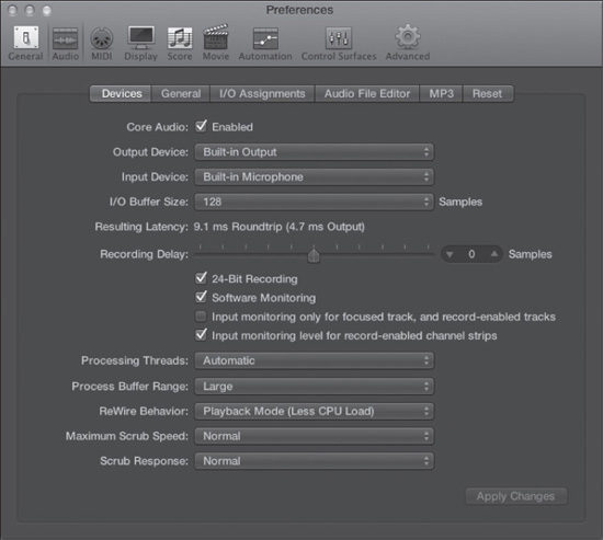
© Apple Inc.
Some of the options in the Devices tab are self-explanatory; others are less so. I’ll briefly go over all of the options here. Because the I/O Buffer Size and Process Buffer Range options are more complex and require detailed explanation, each will get its own section later in this chapter. The Software Monitoring setting is discussed in Chapter 5, “Transport Controls and Recording.”
![]() Core Audio: Select the Core Audio checkbox if your audio interface uses the Core Audio driver.
Core Audio: Select the Core Audio checkbox if your audio interface uses the Core Audio driver.
![]() Output Device: Use this menu to select the audio device to which Logic will output audio.
Output Device: Use this menu to select the audio device to which Logic will output audio.
![]() Input Device: Use this menu to select the audio device from which Logic will receive audio.
Input Device: Use this menu to select the audio device from which Logic will receive audio.
![]() I/O Buffer Size: This is explained in detail in the “I/O Buffer Size” section later in this chapter.
I/O Buffer Size: This is explained in detail in the “I/O Buffer Size” section later in this chapter.
![]() Resulting Latency: This tells what your I/O latency will be at the current I/O Buffer Size setting, along with the specific value of the output latency.
Resulting Latency: This tells what your I/O latency will be at the current I/O Buffer Size setting, along with the specific value of the output latency.
![]() Recording Delay: If your audio interface properly discloses how long it takes for audio to travel from its inputs into the computer, Logic can automatically compensate for this delay to make sure that everything you record appears in Logic’s Tracks area exactly at the instant you recorded it. However, some devices do not report their delay, so Logic would have no way of knowing exactly how to compensate for the record offset caused by your hardware. The Recording Delay parameter enables you to manually adjust Logic’s recording offset compensation so that you can even compensate for devices that do not report their delay. If this sounds complicated, and/or if your tracks don’t sound like they are out of time, you don’t need to worry about this parameter. For most modern interfaces, you won’t need to adjust this.
Recording Delay: If your audio interface properly discloses how long it takes for audio to travel from its inputs into the computer, Logic can automatically compensate for this delay to make sure that everything you record appears in Logic’s Tracks area exactly at the instant you recorded it. However, some devices do not report their delay, so Logic would have no way of knowing exactly how to compensate for the record offset caused by your hardware. The Recording Delay parameter enables you to manually adjust Logic’s recording offset compensation so that you can even compensate for devices that do not report their delay. If this sounds complicated, and/or if your tracks don’t sound like they are out of time, you don’t need to worry about this parameter. For most modern interfaces, you won’t need to adjust this.
![]() 24-Bit Recording: If you want to record into 24-bit audio files, keep this checkbox checked. Using 24-bit files takes up more processing power and hard disk space, so some users prefer to record at 16-bit to conserve their CPU and hard disk. In addition, some older or inexpensive audio interfaces do not have 24-bit recording capability. These days, almost every device is capable of 24-bit recording. As explained in Chapter 1, “Introducing Logic Pro X,” it is advantageous to use the highest bit rate you can, so you should keep this option selected if your system is capable.
24-Bit Recording: If you want to record into 24-bit audio files, keep this checkbox checked. Using 24-bit files takes up more processing power and hard disk space, so some users prefer to record at 16-bit to conserve their CPU and hard disk. In addition, some older or inexpensive audio interfaces do not have 24-bit recording capability. These days, almost every device is capable of 24-bit recording. As explained in Chapter 1, “Introducing Logic Pro X,” it is advantageous to use the highest bit rate you can, so you should keep this option selected if your system is capable.
![]() Software Monitoring: This option selects or deselects software monitoring. Software monitoring is explained in detail in Chapter 5.
Software Monitoring: This option selects or deselects software monitoring. Software monitoring is explained in detail in Chapter 5.
![]() Input Monitoring Only for Focused Track, and Record-Enabled Tracks: This option enables software monitoring for the currently selected track and/or any record-enabled tracks.
Input Monitoring Only for Focused Track, and Record-Enabled Tracks: This option enables software monitoring for the currently selected track and/or any record-enabled tracks.
![]() Input Monitoring Level for Record-Enabled Channel Strips: Selecting this option enables you to set a separate record-monitoring level for a record-enabled track. You can record-enable a track, then set the level fader for that track to the level at which you wish to monitor while recording. When you disengage the Record button for that track, the level fader will return to its previous setting. This does not affect the input level of your source! Therefore, you must still take care to properly set your input levels on your audio interface to avoid overloading your converters.
Input Monitoring Level for Record-Enabled Channel Strips: Selecting this option enables you to set a separate record-monitoring level for a record-enabled track. You can record-enable a track, then set the level fader for that track to the level at which you wish to monitor while recording. When you disengage the Record button for that track, the level fader will return to its previous setting. This does not affect the input level of your source! Therefore, you must still take care to properly set your input levels on your audio interface to avoid overloading your converters.
![]() Processing Threads: The Processing Threads setting determines how many of your available processing cores will be used for rendering audio. The Automatic setting gives Logic the ability to automatically decide how many processing threads will open. If you want, you can designate the number of cores Logic will use by selecting a number from the menu. How many cores you can access depends on your computer’s processor.
Processing Threads: The Processing Threads setting determines how many of your available processing cores will be used for rendering audio. The Automatic setting gives Logic the ability to automatically decide how many processing threads will open. If you want, you can designate the number of cores Logic will use by selecting a number from the menu. How many cores you can access depends on your computer’s processor.
![]() Process Buffer Range: The Process Buffer Range setting is explained in detail in the “Process Buffer Range” section later in this chapter.
Process Buffer Range: The Process Buffer Range setting is explained in detail in the “Process Buffer Range” section later in this chapter.
![]() ReWire Behavior: ReWire is a technology developed by Propellerhead Software (the Swedish audio software company famous for ReCycle, ReBirth, and Reason) to allow separate standalone audio applications to interoperate. Setting up Logic as a ReWire host is addressed in detail in the section “Using ReWire 2 Instruments” in Chapter 9. This setting determines whether Logic utilizes ReWire in Playback mode, which takes up less CPU processing, or in Live mode, which allows you to send MIDI from Logic to your ReWire applications with lower latency, at the expense of a high CPU load.
ReWire Behavior: ReWire is a technology developed by Propellerhead Software (the Swedish audio software company famous for ReCycle, ReBirth, and Reason) to allow separate standalone audio applications to interoperate. Setting up Logic as a ReWire host is addressed in detail in the section “Using ReWire 2 Instruments” in Chapter 9. This setting determines whether Logic utilizes ReWire in Playback mode, which takes up less CPU processing, or in Live mode, which allows you to send MIDI from Logic to your ReWire applications with lower latency, at the expense of a high CPU load.
![]() Maximum Scrub Speed: Scrubbing refers to using the mouse to move the playhead over an audio file while Logic is paused to play it back as opposed to simply clicking Play. You can also scrub if you click and drag on a region with the Scissors tool. This option is particularly useful if you are doing some very fine editing and are listening for a specific point in the song. The Maximum Scrub Speed option determines the maximum possible playback speed when you scrub: Normal or Double Speed. When you select Normal, even if you scrub your mouse as quickly as you can across a section of audio, you’ll never hear it faster than real time. If you select Double, you will hear the section play back at double the normal speed. You might want to change the scrub speed if you want to be able to quickly scrub through your song.
Maximum Scrub Speed: Scrubbing refers to using the mouse to move the playhead over an audio file while Logic is paused to play it back as opposed to simply clicking Play. You can also scrub if you click and drag on a region with the Scissors tool. This option is particularly useful if you are doing some very fine editing and are listening for a specific point in the song. The Maximum Scrub Speed option determines the maximum possible playback speed when you scrub: Normal or Double Speed. When you select Normal, even if you scrub your mouse as quickly as you can across a section of audio, you’ll never hear it faster than real time. If you select Double, you will hear the section play back at double the normal speed. You might want to change the scrub speed if you want to be able to quickly scrub through your song.
![]() Scrub Response: This setting determines how quickly the scrub function will react to changes in your mouse speed. Your options are Slow, Normal, Fast, and Faster. The faster the response, the more the playback reflects your actual speeding up and slowing down, but the more jerky the sound will be if you don’t keep your speed extremely steady.
Scrub Response: This setting determines how quickly the scrub function will react to changes in your mouse speed. Your options are Slow, Normal, Fast, and Faster. The faster the response, the more the playback reflects your actual speeding up and slowing down, but the more jerky the sound will be if you don’t keep your speed extremely steady.
Adjusting the Audio Hardware Buffers
One of the most important reasons to open the Devices tab of the Audio Preferences window is to adjust the various input and output buffers. Adjusting buffers is how you fine-tune Logic’s performance to get the most out of your system. To do this properly, it is important to know what each of the buffers does so you can tailor the settings to meet your requirements exactly.
The fundamental concept is that it takes a set amount of time for the CPU to perform a given amount of work. Because timing is so integral to making music, having control over the exact amount of time it takes the CPU to complete a given task is crucial. Logic allows users to have independent control over two separate but related audio buffers: the input/output (I/O) buffer and the process buffer.
I/O BUFFER SIZE
When you record audio into Logic, it naturally takes a certain amount of time before you hear it played back through the audio interface’s outputs. First, the audio has to travel from your audio interface into the audio driver of your audio interface. The driver then passes the signal information to Logic. After Logic records the audio onto your hard drive, Logic returns the audio to your audio driver for output, and finally the driver sends the audio to your interface. This is shown in Figure 3.32.
Figure 3.32 The signal flow of audio into and out of your computer.
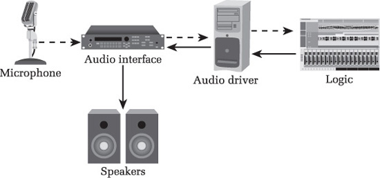
© Cengage Learning.
As this figure shows, the audio driver is in charge of regulating the input and output of audio to and from the application. To do this effectively and in perfect synchronization, the audio driver passes to Logic a chunk of audio that consists of a variable number of samples, and Logic then sends to the driver chunks of audio with that same number of samples. The amount of time that elapses in this process is called latency.
If the number of samples in each chunk of audio is very small, the latency will be very low. The drawback is that the audio driver has to work very quickly to keep those small chunks of audio moving. This requires more CPU power and, if the audio drivers are not well written, can cause audible crackles and pops as the audio driver struggles to keep up with the demands placed on it. If the number of samples in each chunk is very large, the driver does not need to work nearly as hard, resulting in a far lower CPU drain and better performance from audio drivers. However, large buffers result in a higher latency.
You can set the size of the buffer using the I/O Buffer Size menu in the Devices tab of the Audio Preferences menu. Figure 3.33 shows the I/O Buffer Size menu.
Figure 3.33 You can select any of these different buffer sizes in the I/O Buffer Size menu.
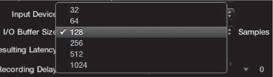
© Apple Inc.
There are a number of situations in which you need your latency to be as low as possible:
![]() To get the most out of software monitoring (see the “Recording, Software Monitoring, and Latency” section in Chapter 5)
To get the most out of software monitoring (see the “Recording, Software Monitoring, and Latency” section in Chapter 5)
![]() To play virtual instruments in real time
To play virtual instruments in real time
![]() To use external hardware alongside playback from Logic
To use external hardware alongside playback from Logic
In these cases, you should set your buffer as low as your system can handle without glitches (audible pops and crackles during playback), which usually ranges between 64 and 256 samples. Otherwise, you can set your buffer to a high setting because higher settings usually offer the best CPU performance—try 512 and 1,024 samples. As a rule, you should start with as low a setting as you can, and if you notice audio glitches or sluggish computer performance due to the CPU strain, slowly raise the I/O Buffer Size value until you reach the lowest comfortable setting. After you change the buffer size, you must then click on Apply Changes. Logic Pro will reset the driver and reload any software instrument’s data that exists in the project, which can take a little while in a full project.
PROCESS BUFFER RANGE
When you use a native audio engine, your computer’s CPU handles all the audio processing. Just as the audio drivers handle audio in chunks to increase efficiency, the CPU also handles audio processing in chunks. The size of these chunks is set with the Process Buffer Range menu. The Process Buffer Range setting may be Small, Medium, or Large. The smaller the buffer, the faster audio is processed, but the more CPU is required, leaving less total CPU power available for other processing. The larger the buffer, the slower the CPU processes audio, which leaves more power available for everything else, such as playing tracks, doing screen redraws, etc.
If your process buffer is too small for your system, your system will quickly run out of power, presenting you with cryptic messages such as “Error: Core Audio too slow” and the like. Regardless of the exact text, the reason is the same: Logic can’t keep up with everything you’re asking it to do. If your buffer is too large, you may find that some operations that rely on a fast response—such as external storage devices, recording, or realtime processing—will become out of sync because each chunk is too large to keep up with the rest of the song. You have to adjust this setting to find the ideal buffer size for your particular system, but in general you should keep the Process Buffer Range setting as small as possible. Most modern computers should be able to handle a Process Buffer Range setting of Small or Medium without a problem. Start with a setting of Small, and then increase it as necessary to find the ideal setting.
Setting Up Your MIDI Hardware
Because most MIDI devices don’t have many configurable options, setting them up is far more straightforward than with audio devices. When connecting your MIDI hardware to your MIDI interface, however, you need to be conscious of MIDI ports.
Selecting MIDI Ports
The most basic MIDI interfaces have a single MIDI IN and a single MIDI OUT jack. However, many MIDI interfaces have multiple jacks (usually two to eight of each). Each pair of IN and OUT jacks is referred to as a MIDI port. You’ll need to keep track of which device you have plugged into which port. Although Logic can detect that something is connected to a MIDI port, it’s up to you to tell Logic what that device is and what it can do. This becomes especially important when you add devices or change the port to which they are connected. You can run into problems such as devices not being detected or, if you select the wrong MIDI port, MIDI data being sent to the wrong devices.
Every external MIDI track in Logic has an Inspector; the second parameter (right under the Icon checkbox) is the Port setting. Figure 3.34 shows an external MIDI track in the main window with its port set to port 2.
Figure 3.34 By looking at the Port setting in the Inspector of this MIDI object, you can quickly determine that the device is connected to port 2 of the MIDI interface.
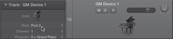
© Apple Inc.
If you change the MIDI ports to which your MIDI devices are connected, make sure that the Port settings of your external MIDI tracks are still accurate. While audio settings are global for all Logic songs, MIDI settings are project-specific and may need to be updated. Ideally, you want to keep your MIDI equipment configured the same way all the time to increase the effectiveness and efficiency of your template. If you remove devices that are being sent MIDI data from Logic, or perhaps you get a new piece of MIDI equipment, be sure to set the MIDI port on those external MIDI tracks to the new device to which you’d like the signals sent. Keeping Logic and your template properly up to date with what MIDI device is connected to which MIDI port is an essential part of setting up and maintaining your system.
Logic Pro and Surround
Surround material is pervasive in modern music and video, from 5.1 DVD-Audio releases to 7.1 SDDS movie releases. Logic Pro offers full surround support, including recording, bouncing, mixing, and processing in a wide variety of surround and legacy formats. Although topics such as surround mixing and bouncing are covered in Chapter 11, knowing what the supported surround formats are and how you can configure your audio interface for surround input is necessary if you are considering using surround in Logic.
Supported Surround Formats
Logic offers the following surround format options:
![]() Quadraphonic: Quadraphonic, or Quad, is a fairly old format whose height of popularity was in the 1970s. The format uses four channels: one right, one left, one right rear, and one left rear.
Quadraphonic: Quadraphonic, or Quad, is a fairly old format whose height of popularity was in the 1970s. The format uses four channels: one right, one left, one right rear, and one left rear.
![]() LCRS (Pro Logic): LCRS is the original Dolby Pro Logic Surround format, which is another four-channel format consisting of left, center, right, and surround (rear) channels.
LCRS (Pro Logic): LCRS is the original Dolby Pro Logic Surround format, which is another four-channel format consisting of left, center, right, and surround (rear) channels.
![]() 5.1 (ITU 775): This is the surround format most commonly in use today. This is the format that 5.1 DVD-Audio uses, and it is typical in home theater systems. This format uses a total of six channels: left, center, right, left rear, right rear, and LFE (low frequency effect).
5.1 (ITU 775): This is the surround format most commonly in use today. This is the format that 5.1 DVD-Audio uses, and it is typical in home theater systems. This format uses a total of six channels: left, center, right, left rear, right rear, and LFE (low frequency effect).
![]() 6.1 (ES/EX): This setting is used for the DTS ES or Dolby Digital EX format. This is a seven-channel format utilizing left, center, right, left rear, surround, right rear, and LFE channels.
6.1 (ES/EX): This setting is used for the DTS ES or Dolby Digital EX format. This is a seven-channel format utilizing left, center, right, left rear, surround, right rear, and LFE channels.
![]() 7.1 (3/4.1): This is a common cinema format similar to 5.1, but with two more surround channels: a left side channel and a right side channel.
7.1 (3/4.1): This is a common cinema format similar to 5.1, but with two more surround channels: a left side channel and a right side channel.
![]() 7.1 (SDDS): SDDS is a Sony format used in movie theaters. It consists of eight channels: left, left center, center, right center, right, left rear, right rear, and LFE.
7.1 (SDDS): SDDS is a Sony format used in movie theaters. It consists of eight channels: left, left center, center, right center, right, left rear, right rear, and LFE.
Setting the Project Surround Format
To set the surround format for your project, you need to open the Audio tab of the Project Settings window by doing one of the following:
![]() Choosing File > Project Settings > Audio
Choosing File > Project Settings > Audio
![]() Pressing Option+P to open the Project Settings window and selecting the Audio tab.
Pressing Option+P to open the Project Settings window and selecting the Audio tab.
Figure 3.35 shows the Audio tab of the Project Settings window. To assign a surround format to your project, simply select your desired format from the Surround Format menu.
Figure 3.35 The Audio tab of the Project Settings window. You can assign a surround format to your project from the Surround Format menu.
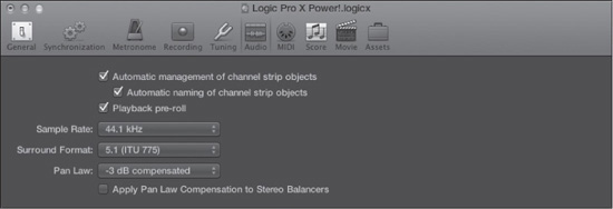
© Apple Inc.
Configuring Surround Inputs
To set the surround input format, open the Input screen of the I/O Assignments tab of the Audio Preferences window (see Figure 3.36). Use the Show As menu to set the desired surround format. Selecting a surround format automatically configures the various input assignment menus to the default input settings for the chosen format. In Figure 3.36, the surround format is 5.1 (ITU 775), and the input assignment menus reflect the default settings. You can reassign any channel to any available input. You can configure surround outputs in the Output screen of the I/O Assignments tab in the same fashion.
Setting Up Your Control Surface
If you have a software controller, you are in for a special treat. A control surface can actually be any MIDI device capable of sending and receiving MIDI in order to control functions within Logic. The most common control surfaces, however, resemble hardware mixers, except instead of controlling audio, they control your Logic software. A full explanation of how to use your control surface is beyond the scope of this book; this section will just focus on how to set up your control surface to work with Logic.
Figure 3.36 The Input screen of the I/O Assignments tab of the Audio Preferences window. You can configure your audio interface for surround input in this screen.
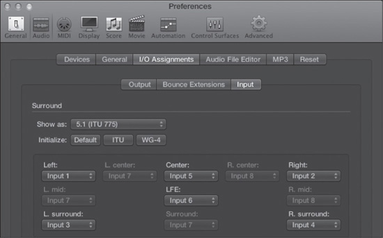
© Apple Inc.
Setting Up a Supported Control Surface
Logic already has complete built-in support for a number of popular control surfaces. As of this writing, Logic Pro X ships with built-in support for the following devices:
![]() CM Labs: Motor Mix
CM Labs: Motor Mix
![]() Euphonix: MC Professional and Artist series controllers
Euphonix: MC Professional and Artist series controllers
![]() Frontier Design: TranzPort
Frontier Design: TranzPort
![]() JL Cooper: CS-32 MiniDesk, FaderMaster 4/100, MCS3
JL Cooper: CS-32 MiniDesk, FaderMaster 4/100, MCS3
![]() Korg: microKONTROL, KONTROL49
Korg: microKONTROL, KONTROL49
![]() M-Audio: iControl
M-Audio: iControl
![]() Mackie Designs: Baby HUI, HUI, Logic Control (Mackie Control), Logic Control XT (Mackie Control XT), Mackie Control C4
Mackie Designs: Baby HUI, HUI, Logic Control (Mackie Control), Logic Control XT (Mackie Control XT), Mackie Control C4
![]() Radikal Technologies: SAC-2k
Radikal Technologies: SAC-2k
![]() Recording Light: Offers MIDI control of a “Recording” light to let people know your session is in live recording mode
Recording Light: Offers MIDI control of a “Recording” light to let people know your session is in live recording mode
![]() Roland: SI-24
Roland: SI-24
![]() Tascam: FW-1884, US-224, US-428, US-2400
Tascam: FW-1884, US-224, US-428, US-2400
![]() Yamaha: 01V96, 02R96, DM1000, DM2000
Yamaha: 01V96, 02R96, DM1000, DM2000
NOTE: Apple is always adding support for new control surfaces, so if you have a control surface that is not listed here, keep checking with Apple to see whether support for it has been added.
Depending on your control surface, you may need a MIDI interface to connect it. (See your control surface’s owner’s manual for instructions on proper hookup.) Logic will automatically detect most control surfaces when you connect them to your system.
You will be presented with the Control Surface Setup window when Logic launches, shown in Figure 3.37. This indicates that Logic was able to sense that you had a control surface plugged in and that all is well.
Figure 3.37 The Control Surface Setup window. If Logic automatically opened to this window, you’re home free. Otherwise, you may need to connect to your control surface manually.
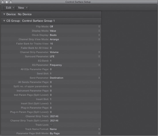
© Apple Inc.
If this window does not detect your control surface immediately, don’t worry, as all is not lost. Simply select New > Scan All Models from the Control Surface Setup window, and Logic will rescan your MIDI interface to find any connected control surfaces. If your control surface does not support automatic scanning, then you need to add it manually by doing the following:
1. Choose New > Install from the Control Surface Setup window.
2. Choose your control surface from the list.
3. Click Add.
If your control surface is found but does not seem to be responding, open the global Logic Pro menu and choose Logic Pro X > Control Surfaces > Rebuild Defaults. That should do the trick. If this works, it means that Logic always knew where your control surface was among your devices, but it was simply not connecting. If this doesn’t work, you’ll need to start looking for loose cables and hardware connections, then try again. If nothing works, don’t be afraid to contact the controller manufacturer’s tech support and ask them to walk you through the connection process.
Once Logic senses your control surface, you’re ready to go. Close the window and bask in the joy of your control surface!
Setting Up Any MIDI Device as a Control Surface
As mentioned, if your control surface is not supported, you can still configure Logic to use it to control the application. If you want to use an unsupported control surface, you will need to set up what each knob, fader, and button on your controller does. The basic procedure is to first click on an onscreen control or menu option. After you have done this, immediately select Logic Pro X > Control Surfaces > Learn Assignment For. (You will notice that the word following “For” will be the control or command you just selected.) Figure 3.38 illustrates how this should work.
Figure 3.38 In this example, the volume slider of the first track in the track Mixer was clicked. As you can see, the Learn Assignment parameter now says “Learn Assignment for ’Pan,’” reflecting that any controller assignment you make will be mapped to the panorama of that track.
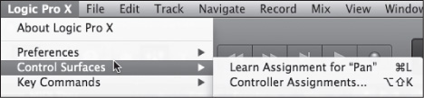
© Apple Inc.
After you select the Learn Assignment command (or press Command+L), you will be presented with the Controller Assignments dialog box shown Figure 3.39. At this point, click the Learn button and twist, press, slide, or otherwise manipulate a control on your MIDI controller, and it will be automatically assigned to the chosen control or command in Logic. You can use this to assign each button, knob, and fader on your MIDI controller to control a function in Logic.
Figure 3.39 When you execute the Learn Assignment command, you will be presented with the Controller Assignments window. Click Learn and move a control on your MIDI device, and it will be assigned to that control or command.
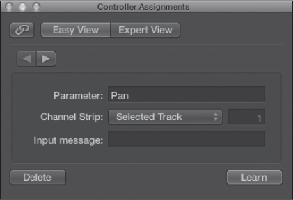
© Apple Inc.
As you can see, this is an amazingly powerful feature in Logic, allowing virtually every aspect of the application to be remotely controlled! As you can also see, going into every detail of this extremely powerful feature would take a whole chapter by itself, and it’s beyond the scope of this book. This description should be enough to get you started with a basic setup. When you want to get into more complex and esoteric assignments, the Logic Pro X Control Surfaces Support online help manual offers a complete description of the Controller Assignments feature.
Saving Your Template
When you are ready to save your template project, select File > Save As Template. You will be presented with the Save As dialog box, already opened to the Project Templates folder in the user directory. Click Save, and your template will be ready for you to use as a starting point any time you need it!
TIP: Being that your template is so important and painstakingly constructed, you most likely will want to save it from being accidentally modified. Luckily, the Mac OS offers two easy methods to protect a file. For either, you’ll need to select your template in the Mac OS Finder and choose File > Get Info, press Command+I, or right-click your template and select Get Info. When the Get Info box appears, you’ll notice two checkboxes. If you select the Stationary Pad checkbox, Logic will open a copy of your template and name it “Untitled” instead of your actual template file; that way, if you accidentally press Return, it creates a new file and doesn’t overwrite your previous template. You may also want to select the second checkbox in the Get Info window, labeled Locked. With this selected, you simply cannot make any changes to the template file without unlocking the file in the Finder first. Either method will protect your template from accidental changes.
Logic’s Use of Mac OS X Directories: You may have already noticed that the Logic Pro X file in your Applications directory does not have a folder around it, as some other programs you may own do. This is because Logic Pro follows Apple’s guidelines for where the support files for applications should go. Logic Pro files are in one of two places.
Factory presets and support files are in the local directory (meaning, at the level of your hard drive):
![]() /Library/Application Support/Logic
/Library/Application Support/Logic
User presets and support files are in your user directory, with ~ being the UNIX symbol for the Home directory for a given user:
![]() ~/Library/Application Support/Logic
~/Library/Application Support/Logic
![]() ~/Music > Audio Music Apps
~/Music > Audio Music Apps
As you can see, there’s really only a single folder to which you’ll be adding information, and that’s the user folder. It’s also very convenient to back up just this one folder and know that all your presets, templates, sampler instruments, and so on have been backed up.
You should now understand the basics of what Logic is and what Logic can do. You should also have completed the basic configuration of your template project. From this point forward, the focus shifts from explaining to exploring. As such, you will encounter many details very quickly. Don’t feel intimidated if you need to slow down or reread a section a few times before you are comfortable with the information. Logic is a very deep program, and it takes time to absorb. In the next chapter, you will start exploring some of the global functions, options, menus, and tracks Logic has to offer. As you learn about new functions in Logic, remember to incorporate those things you find useful into your template and its screensets!