Chapter 11. Network Virtualization Overlays
This chapter discusses one of the most important incarnations of Software-Defined Networking (SDN) for clouds and data centers: Network Virtualization Overlay (NVO).
Chapter 10 introduced the Edge Forwarder concept in detail. Now, let’s have another look at it from a functional and service-centric perspective. In the context of NVO, Edge Forwarders support multitenancy by implementing flexible network policies that rely on an overlay transport mechanism. You should know that this is basically the definition of a VPN; thus in this chapter, Edge Forwarders are actually VPN Forwarders.
One type of VPN Forwarder, network devices that implement L3 VPNs and L2 VPNs, has already been the subject of many pages in the first part of this book. These PE routers can run in dedicated physical platforms, or virtualized in a container, or as a VM in a hypervisor, or even directly on a bare-metal server. Anyway, physical or virtual, they perform the same function—of course, performance differs.
This chapter focuses on two other VPN Forwarder types:
-
Host operating system (OS) that implements virtual networks (VNs) while acting at the same time as a Hypervisor or as a Container Engine. As you are about to see, this is not the same as a network OS running on a virtual machine (VM). From the computing perspective, it is lower in the stack and hence more native. But these approaches are not mutually exclusive; actually, they combine nicely in Network Functions Virtualization (NFV), which is covered in Chapter 12.
Let’s begin with the first type of VPN Forwarders in this short list. They are at the heart of SDN. Depending on the actual implementation, they are called vRouters or vSwitches. Both perform a similar function but not all vSwitches are overlay-capable.
Several vendors have developed products that create overlay virtual networks in order to achieve connectivity between VMs, containers, and the physical world. As of this writing, it is an emerging market. This book’s SDN chapter block (10, 11, 12, and 15) focuses on illustrating the technology, not product comparisons. In the end, concepts are quite universal and network solutions are meant to interoperate.
As of this writing, there are several NVO production-ready solutions on the market, and one of them is OpenContrail. Here are the reasons why OpenContrail was chosen for this book’s NVO examples:
-
It happens to be a solution that the authors know well. Resources are limited in every project, and this book is no exception. A choice had to be made. If you enjoy this book, a future second edition would likely cover other vendors’ SDN solutions and multivendor interoperability.
-
OpenContrail is a deployed, production-ready SDN solution with a comprehensive feature set in all the key areas, including network policy and network service architecture, providing a wide range of overlay flavors from which to choose.
-
Like Open vSwitch (OVS), OpenContrail is an open source project.
-
Unlike OVS, OpenContrail was inspired since day one by BGP and MPLS service architecture. It clearly decouples overlay from underlay, and control plane from forwarding plane. After policies are centrally defined, distributed vRouters are empowered to locally create flows with no intervention from the controller—which later gets information about the flows for analytics purposes. Having this architecture since its conception, OpenContrail vRouter has better scalability, performance, and robustness than current OVS implementations, which are influenced by OpenFlow’s initial design approach.
As for Network Virtualization Controllers (NVCs), OpenContrail is also kept as a main reference for the same reasons. For the record, other popular solutions include OpenDaylight (ODL), Nuage, and VMware’s NSX.
OpenContrail in a Nutshell
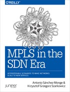
Chapter 10 explains the generic architecture of cloud SDN solutions. This chapter’s Figure 11-1 is similar to Figure 10-12, except that now we are actually using OpenContrail terms (such as vRouter) and actual protocols between the different functions.
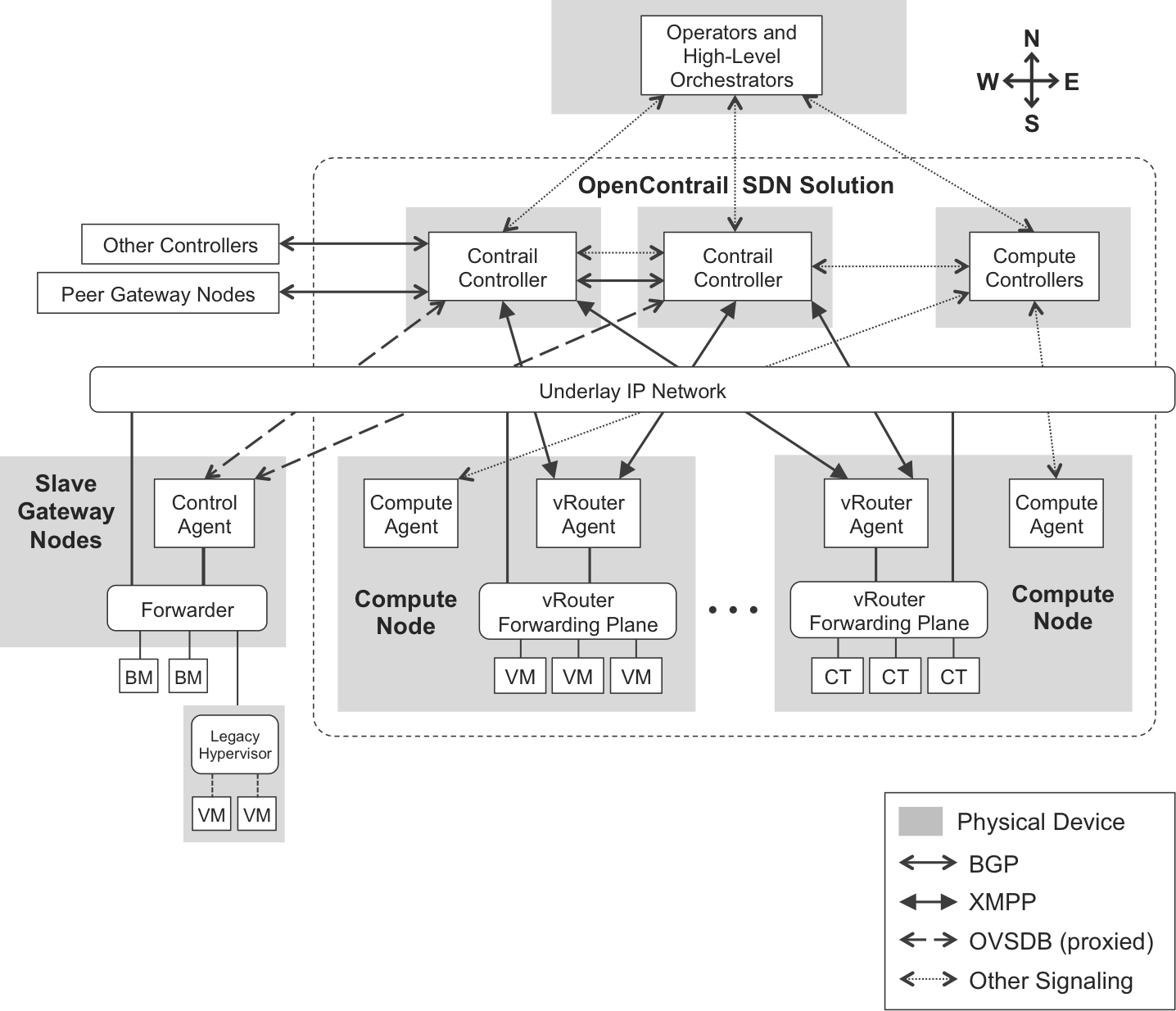
Figure 11-1. OpenContrail control-plane architecture
OpenContrail Controllers
Although in Figure 11-1 each OpenContrail Controller is represented as a single box, it is actually the combination of at least four different software components or nodes.
Note
Beware of the term node: here, it is just software running on general-purpose x86 processors. Each of these nodes can run on the same or on different physical servers—and on the same or on different VMs.
The following description is from the OpenContrail book in Juniper’s Day One library:
All nodes of a given type run in an active-active configuration, so no single node is a bottleneck. This scale-out design provides both redundancy and horizontal scalability.
Configuration nodes, which are responsible for translating the high-level data model into a lower-level form suitable for interacting with network elements.
Control nodes, which are responsible for propagating this low-level state to and from network elements and peer systems in an eventually consistent way.
Analytics nodes, which are responsible for capturing real-time data from network elements, abstracting it, and presenting it in a form suitable for applications to consume.
In more recent OpenContrail versions, controllers also have database nodes.
From a networking perspective, the control node is the most interesting because it’s the one performing all the network protocol signaling that is required to build overlay networks. Control nodes speak BGP in the West-East direction, and eXtensible Messaging and Presence Protocol (XMPP) in the North-South direction.
Note
ToR Service Nodes (covered later) implement a proxy function that translates XMPP messages from and to Open vSwitch Database Management (OVSDB).
Compute, Gateway, and Service Nodes
The other node types have a more physical meaning:
-
Compute nodes are an intrinsic part of OpenContrail.
-
Gateway and service nodes are external and interact with OpenContrail.
Again, paraphrasing the OpenContrail Day One book:
Compute nodes are general-purpose virtualized servers that host VMs. These VMs may be tenant running general applications, or these VMs may be service VMs running network services such as a virtual load balancer or virtual firewall. Each compute node contains a vRouter that implements the forwarding plane and the distributed part of the control plane.
Gateway nodes are physical gateway routers or switches that connect the tenant virtual networks to physical networks such as the Internet, a customer VPN, another data center, or to non-virtualized servers.
Service nodes are physical network elements providing network services such as Deep Packet Inspection (DPI), Intrusion Detection (IDP), Intrusion Prevention (IPS), WAN optimization, Network Address Translation (NAT) and load balancing. Service chains can contain a mixture of virtual services (implemented as VMs on compute nodes) and physical services (hosted on service nodes).
Gateway nodes can also run as a VM, and the service function can definitely be virtualized. Anyway, all these node terms (Compute, Gateway, Service, and ToR service) typically refer to a physical host or device.
Compute nodes
Like other SDN solutions, OpenContrail is a networking product. To avoid reinventing the wheel, OpenContrail integrates with existing compute virtualization solutions that are responsible for managing, instantiating, and moving VMs or containers:
-
If OpenStack is used as the Compute Controller + Agent, there are two virtualization options: Linux KVM (Kernel-based Virtual Machine) and Docker. The first is a VM-based hypervisor; the second is a container engine.
-
OpenContrail can also integrate with VMware vCenter as the Compute Controller + Agent, using VMware ESXi as the hypervisor. This requires interconnecting OpenContrail’s vRouter to VMware’s vSwitch, and dynamically mapping vSwitch’s VLANs to vRouter’s Virtual Networks.
-
As of this writing, there is ongoing work to evaluate a possible integration with Kubernetes as the Compute Controller + Agent, using Docker as the container engine; however, it is not yet implemented.
In an analogy to a multiforwarder network device:
-
A compute node is like a line card.
-
A vRouter agent runs in user space and is analogous to a control agent in a line card.
-
The vRouter’s forwarding plane runs in the kernel and is analogous to a forwarding engine.
Gateway nodes
Figure 11-1 shows that there are actually two types of gateway nodes:
-
Peer gateway nodes are capable of building their own overlays. They are typically PEs and establish iBGP sessions to the control nodes.
-
Slave gateway nodes can build overlays as instructed by the control node.
Strictly speaking, nothing prevents a gateway node from running in a VM or container.
Service nodes
Chapter 12 provides more detail on the topic. Service nodes have nothing to do with ToR service nodes.
ToR service nodes
OpenContrail controllers are also capable of extending overlay networks to ToR switches that connect legacy hosts and hypervisors. This overlay extension is performed by ToR service nodes, which have nothing to do with the aforementioned service nodes. ToR service nodes implement the intelligence to act as a control-plane proxy between control nodes and ToR devices.
Case Study: A Private Cloud
One of the most powerful applications of SDN solutions like OpenContrail is subscriber access to a private cloud, as illustrated in Figure 11-2. Service providers (SPs) can offer this access in the context of Infrastructure as a Service (IaaS), Platform as a Service (PaaS), or Software as a Service (SaaS). Or, put all together, XaaS.
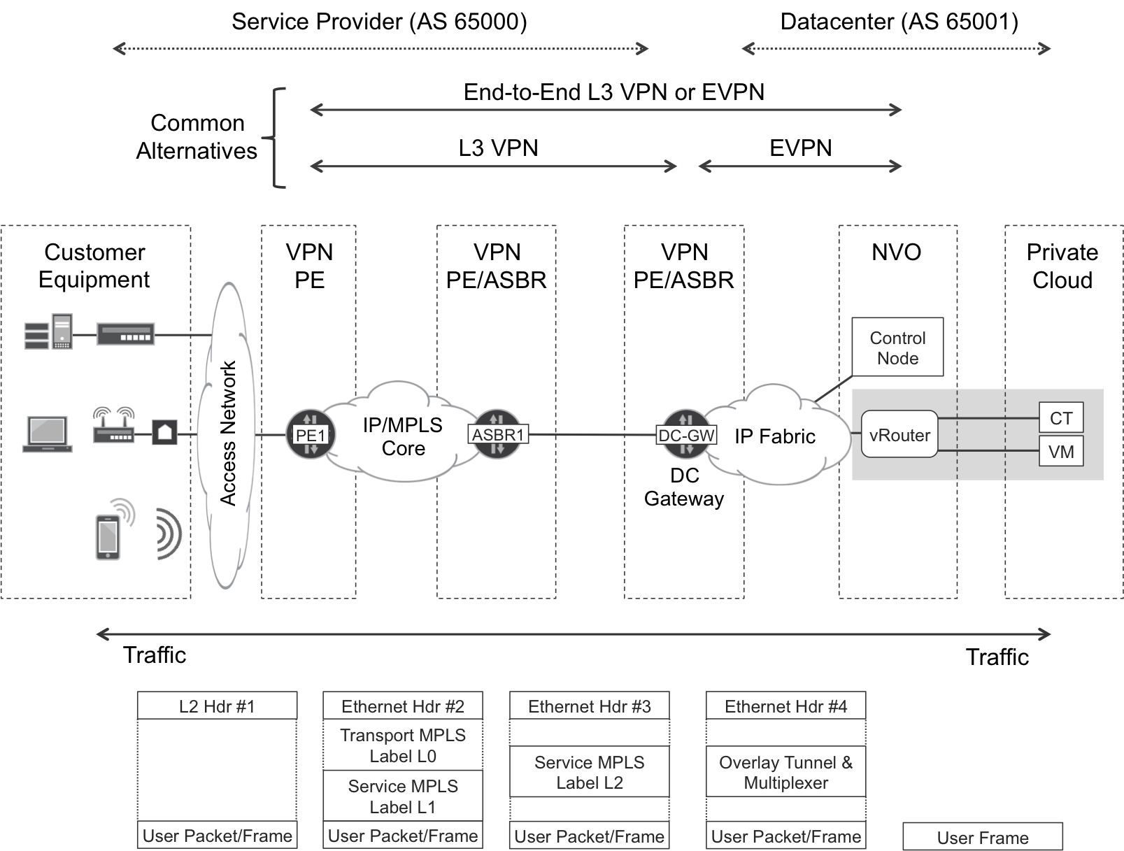
Figure 11-2. Subscriber access to a private cloud
As soon as you associate a VM—or a container—interface to a Virtual Network with OpenContrail, the VM is immediately reachable by the subscribers, and vice versa. This is a very cool example of a natural integration between SDN and BGP/MPLS services.
Note
Security is implicit because it is a VPN service: subscribers do not need to establish IPSec or Secure Socket Layers (SSL) tunnels toward their private cloud.
Let’s discuss the contents of Figure 11-2, moving from right to left:
-
VMs and containers are like CEs. They are totally unaware of the overlay, and simply send and receive Ethernet frames—which are typically untagged.
-
vRouters are like PEs. They can perform the role of either an Ethernet VPN (EVPN) or an IP VPN PE.
-
Like ASBR1, the data center gateway is an Option B Autonomous System Border Router (ASBR). Alternatively, you can merge the two ASBRs into one Area Border Router (ABR). In any case, the data center gateway changes (into a local address) the BGP next hop of the VPN routes that it reflects; as Chapter 9 details, this triggers a new service label allocation. Although it is completely optional to instantiate a local VRF and/or EVPN instance at the data center gateway, doing so can be advantageous because it allows performing route summarization and applying advanced routing policies.
-
Further to the left, it is a classic SP network.
At the bottom of Figure 11-2, notice the User Packet/Frame box. Indeed, it can be an L3 packet or an L2 frame depending on whether the service is EVPN or IP VPN. Thanks to EVPN’s hooks into the L3 world, it is possible to combine EVPN for intrasubnet traffic with IP VPN for intersubnet traffic (this combination is known in OpenContrail as L2_L3 mode). Extending EVPN end-to-end to the subscriber is technically feasible, but it is a bad practice in general to stretch L2 domains.
Although it is not shown in Figure 11-2, OpenContrail also provides communication inside the data center. This makes it possible for VMs running in the same or different vRouters—and for applications running outside OpenContrail—to communicate with one another inside the data center network.
Let’s look at the case study in detail. The focus is on SDN because BGP/MPLS VPNs in physical PEs are already covered in earlier chapters.
For simplicity, Figure 11-3 shows all of the controller functions in the same physical server. Anyway, the focus is on the control node. OpenContrail supports two forwarding modes: pure L3 and mixed L2_L3. The simplest one is pure L3, so let’s begin with it.

Figure 11-3. Infrastructure and VPN addressing—L3 mode
You can see two types of addressing:
-
Infrastructure IPv4 addresses (10.0.10.x/31), which reside in the global routing table and provide underlay connectivity through the IP fabric.
-
VPN overlay addresses (10.1.1.1/32, 10.2.20.10/32, 10.2.2.0/24). These correspond to subscribers, the data center gateway loopback, and VMs, respectively. The same address scheme is used for VPNs Red and Blue. This is fine: they are VPNs after all!
Let’s go through the entire signaling process that enables a private cloud service, step by step.
vRouter-VM Link Addressing
This book focuses on technology and does not include an OpenContrail user guide. Very brief GUI pointers are provided so you can easily match the concepts to the actual configuration hierarchies in OpenContrail.
Note
In general, anything that OpenContrail GUI can do, you can also do by using OpenContrail’s northbound RESTful API.
Although other options are available, the following Virtual Machine Manager GUI pointers (steps 1 and 3 below) assume that the Compute Controller and Agents are based on OpenStack:
-
The first administrative step in VM addressing is to create a project within OpenStack Horizon GUI: Admin→Identity Panel→Projects. This book’s examples use a project named mpls-in-the-sdn-era. A project is typically associated to a tenant, and it supports one or more VNs.
-
In the context of the new project, define the VNs (Red, Blue) in OpenContrail GUI: Configure→Networking→Networks. You can think of a VN as a set of IP subnets with some additional properties: zero or more route targets (RTs), optionally a VXLAN Network Identifier (VNI), and so on. Each of these IP subnets can be broken into /32 addresses that are assigned to the endpoints of VM-vRouter (CE-PE) links.
-
VMs are defined and instantiated through the OpenStack Horizon GUI: Project→ Instances→Launch Instance. Each VM typically has one or more VN interfaces (vNICs), and each vNIC is connected to a vRouter’s tap interface.
A vNIC and a tap interface are the two ends of a CE—PE point-to-point link. Both interfaces are internally linked together, and they are dynamically created as soon as a new VM is spawned. A given tap interface in a vRouter belongs to one and only one VN, and it is connected to a single VM.
Is a VN like a VRF? Almost! Strictly speaking, the OpenContrail term for a VRF is Routing Instance (RI). RIs are implicitly configured through their parent VNs, not directly. By default, there is only one VRF for each VN. On the other hand, Chapter 3 explains the extranet concept, in which VRF:VPN mappings are N:1 instead of 1:1. Similarly, the VRF:VN mappings are N:1. For the moment, in simple scenarios such as that presented in Figure 11-3, VN Red only has one VRF called Red:Red. Note that it is sometimes represented as VRF Red for graphical reasons.
As in a physical PE, a VRF can have local and remote routes. In addition, remember that a CE can have several uplinks, each connected to a different (or the same) VRF at the PE. Likewise, a VM can have several vNICs, each connected to a different VRF at the vRouter. In this first example, each VM has only one vNIC.
One of the most striking aspects of Figure 11-3 is the fact that the 10.2.2.1 address is present multiple times in the same VRF—on the vRouter side. Let’s focus on VRF Red. The first and second host addresses—in this case, 10.2.2.1 and 10.2.2.2—are automatically reserved for the VM’s default gateway and DNS server, respectively. Both of these functions are provided by the vRouters. Their tap interfaces all have the same MAC address 00:00:5e:00:01:00.
Note
Having a deterministic IP and MAC address on the vRouter tap interfaces provides perfect conditions for VM mobility in L3 architectures. Chapter 8 discusses a similar scenario, in which all the IRBs in a given subnet were configured with the same IP and MAC addresses.
The 10.2.2.0/24 network is not advertised by the control node, only the /32 routes assigned to the VMs are. Now, suppose that VM Red_1A sends an ARP request to resolve 10.2.2.102 (at Red_2A) or 10.2.2.103 (at Red_1B). If vRouter_1 knows the corresponding /32 L3 route, vRouter_1 sends an ARP reply to VM Red_1A, providing the well-known MAC address that it uses on all the vRouter-VM links (00:00:5e:00:01:00). This is an intelligent ARP proxy process where the destination VM does not receive any (original or proxied) ARP request packets originated by other VMs.
Note
In L3 mode, the vRouter acts like an L3 router, as opposed to a vSwitch. In L2_L3 mode, the vRouter acts like an L2/L3 switch from the perspective of the VMs.
vNICs get IPv4/IPv6 and MAC addresses from the control node. Figure 11-3 shows five VMs, with one vNIC each—some in VRF Red and others in VRF Blue. As you might expect in a VPN, vNICs in VRF Red can communicate with one another, but not with vNICs in VRF Blue (by default). When you create a new VM, the Compute Controller—in this example, OpenStack—communicates the configured vNIC-to-VN mappings to the OpenContrail controller. Based on this information, the latter assigns IPv4/IPv6 and MAC addresses to each vNIC.
Initializing vNICs—XMPP as a DHCP-Like Protocol
XMPP, formerly known as Jabber, is a communications protocol for message-oriented middleware based on eXtensible Markup Language (XML). It implements a series of functions such as Subscribe, Publish, and Update that make it suitable for the communication between the centralized control plane (control node) and the control agents (vRouter agents).
One of the primary functions that XMPP performs in OpenContrail is the assignment of all the network attributes of a vNIC, including the VRF to which it belongs, its IP and MAC addresses, security, policies, and so on. This information makes it possible for the vRouter to act as a DHCP server in the context of VM addressing, as shown in Figure 11-4.
Figure 11-4. VM addressing—XMPP and DHCP
XMPP Subscribe Request messages are very simple, as demonstrated in Example 11-1.
Example 11-1. XMPP—vRouter agent sends Subscribe Request for a VM
1     <?xml version="1.0"?>
2     <iq type="set" from="vrouter_1"
3         to="network-control@contrailsystems.com/config">
4       <pubsub xmlns="http://jabber.org/protocol/pubsub">
5         <subscribe node="virtual-machine:
6                          9747613d-a93a-43f9-b5aa-de747fc96d44"/>
7       </pubsub>
8     </iq>
This message goes from the control agent at vRouter_1 to the control node (lines 2 and 3). It is triggered by the creation of VM Red_1A in the context of the Compute Controller and Agent (in this case, OpenStack Nova). These compute control elements had already communicated the vNIC-to-VN mappings (in this case, eth0:Red) to OpenContrail.
The internal VM ID (line 6) is different from the VM’s user-friendly name (Red_1A).
Let’s see the XMPP configuration update from Figure 11-4 in more detail, as shown in Example 11-2.
Example 11-2. XMPP—Configuration Update to a vRouter Agent
1     <?xml version="1.0"?>
2     <iq type="set" from="network-control@contrailsystems.com"
3         to="default-global-system-config:vrouter_1/config">
4       <config>
5         <update>
6           <node type="virtual-machine">
7             <name>9747613d-a93a-43f9-b5aa-de747fc96d44</name>
8           </node>
9           <link>
10            <node type="virtual-router">
11              <name>default-global-system-config:vrouter_1</name>
12            </node>
13            <node type="virtual-machine">
14              <name>9747613d-a93a-43f9-b5aa-de747fc96d44</name>
15            </node>
16            <metadata type="virtual-router-virtual-machine" />
17          </link>
18          <node type="virtual-machine-interface">
19            <name>default-domain:mpls-in-the-sdn-era:
20                  75fa145a-07c6-4c84-98b7-3e793fc540b4</name>
21            <virtual-machine-interface-mac-addresses>
22              <mac-address>02:75:fa:14:5a:07</mac-address>
23            </virtual-machine-interface-mac-addresses>
24          </node>
25          <link>
26            <node type="virtual-machine-interface">
27              <name>default-domain:mpls-in-the-sdn-era:
28                    75fa145a-07c6-4c84-98b7-3e793fc540b4</name>
29            </node>
30            <node type="virtual-machine">
31              <name>9747613d-a93a-43f9-b5aa-de747fc96d44</name>
32            </node>
33            <metadata type="virtual-machine-interface-virtual-machine"/>
34          </link>
35          <link>
36            <node type="virtual-machine-interface">
37              <name>default-domain:mpls-in-the-sdn-era:
38                    75fa145a-07c6-4c84-98b7-3e793fc540b4</name>
39            </node>
40            <node type="virtual-network">
41              <name>default-domain:mpls-in-the-sdn-era:Red</name>
42            </node>
43            <metadata type="virtual-machine-interface-virtual-network"/>
44          </link>
45          <node type="instance-ip">
46            <name>d8ba77df-df69-450b-b4d5-daeb53163655</name>
47            <instance-ip-address>10.2.2.101</instance-ip-address>
48            <instance-ip-family>v4</instance-ip-family>
49          </node>
50          <link>
51            <node type="instance-ip">
52              <name>d8ba77df-df69-450b-b4d5-daeb53163655</name>
53            </node>
54            <node type="virtual-machine-interface">
55              <name>default-domain:mpls-in-the-sdn-era:
56                    75fa145a-07c6-4c84-98b7-3e793fc540b4</name>
57            </node>
58            <metadata type="instance-ip-virtual-machine-interface"/>
59          </link>
60        </update>
61      </config>
62    </iq>
XMPP Configuration Update messages contain a graph structure with nodes and links between nodes. This structure is like a network, but its nodes are not necessarily network nodes: they can be virtually anything. Unlike relationships between objects in relational databases, which are strictly unidirectional, these links can be interpreted as bidirectional.
Warning
The concept of node in an XMPP configuration update message has absolutely nothing to do with OpenContrail’s architectural elements, which are also called nodes (control node, compute node, etc.).
The message in Example 11-2 goes from a control node to the control agent at vRouter_1 (lines 2 and 3). It contains the following nodes:
-
Virtual Machine <VM_ID> (lines 6 through 8). This ID matches Example 11-1, line 6, and it is different from the VM’s user-friendly name (Red_1A).
-
VM Interface <vNIC_ID> (lines 18 through 24). The most important property of this node is a MAC address assigned by the control node.
-
Instance IP (lines 45 through 49). Its most important element is an IP address (10.2.2.101).
The rest of the message is a series of links between pairs of nodes that are either defined in this XMPP configuration update message or in previous ones:
-
VM <VM_ID> is linked to the vRouter named vrouter_1 (lines 9 through 17).
-
VM Interface <vNIC_ID> is linked to VM <VM_ID> (lines 25 through 34).
-
VM Interface <vNIC_ID> is linked to VN Red (lines 35 through 44).
-
Instance IP 10.2.2.101 is linked to VM Interface <vNIC_ID> (lines 50 through 59).
Note
For brevity, some data has been omitted from Example 11-2, such as the vNIC-to-security group link, or the routing instance (Red:Red) information. Chapter 12 discusses the latter topic further.
From the perspective of VM Red_1A, vRouter_1 acts as a DHCP server, as an IPv4 default gateway, and as a DNS server. Now that VM Red_1A has an interface with an IPv4 address, it can communicate with the outside world. But, can vRouter_1? Let’s see how a vRouter communicates with other vRouters and with gateway nodes.
Interconnecting VMs—XMPP as a BGP-Like Protocol
In the context of SDN, probably the most important function of XMPP is its ability to perform the same function as Multiprotocol BGP (MP-BGP) in signaling overlay networks. XMPP is as powerful and scalable as BGP and it has the same extensibility as XML. Unlike BGP, which is mainly a West-East protocol, XMPP has its application as a southbound protocol. This routing application of XMPP is defined in draft-ietf-l3vpn-end-system: BGP-signaled end-system IP/VPNs. As you will soon see, you can easily extend XMPP to also signal EVPNs.
Let’s suppose that the 10.2.2.0/24 subnet in VN Red has been configured with the following range of IPs that can be assigned to VMs: 10.2.2.101–10.2.2.200. Let’s further suppose that VMs with a vNIC in Red VN are started in the following order: Red_1A, Red_2A, and Red_1B.
vRouter subscribes to a VRF
Figure 11-5 illustrates how vRouter_1 and vRouter_2 first subscribe to the routing instance Red:Red, and then exchange VM host routes through the control node.
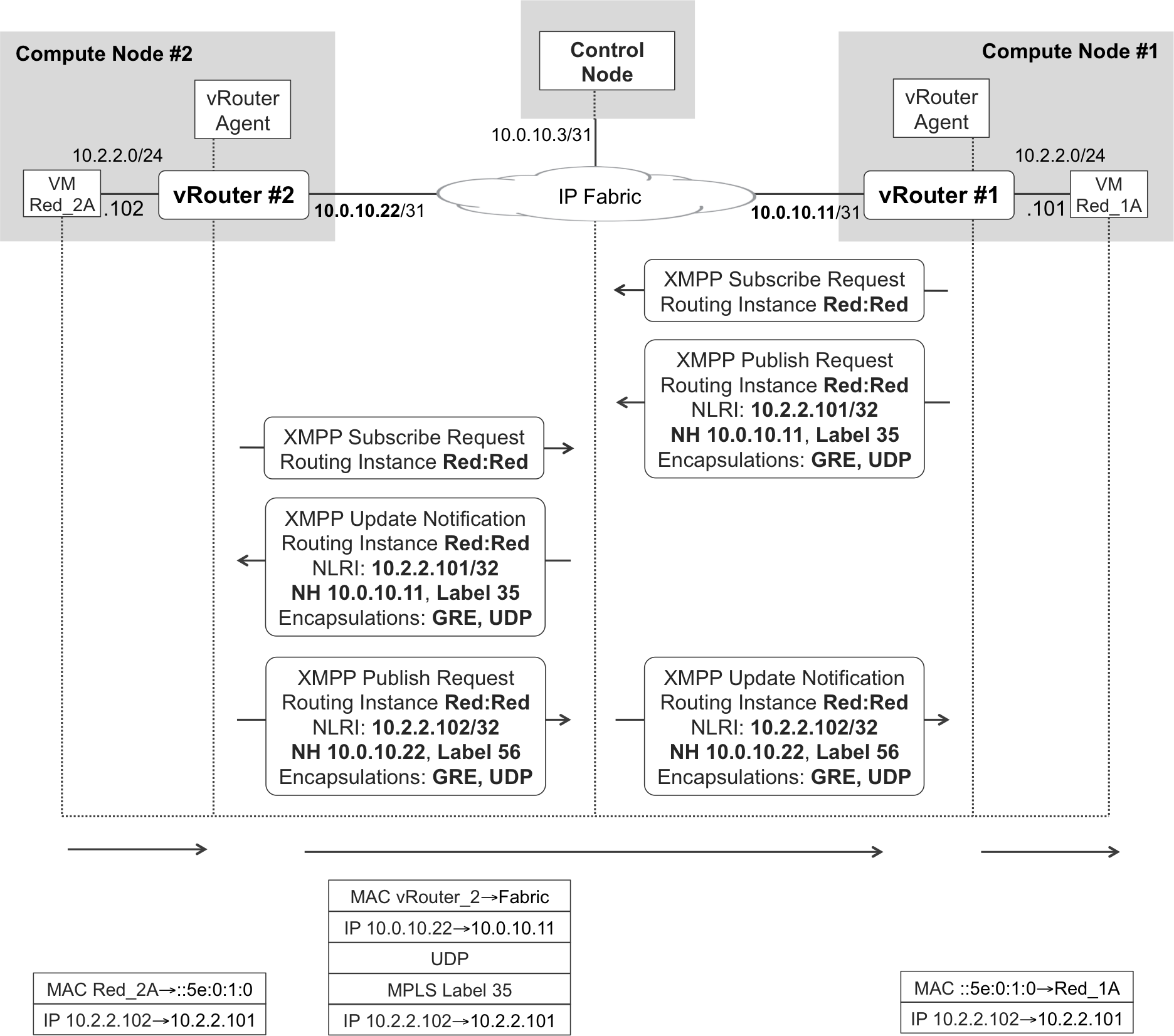
Figure 11-5. XMPP routing and inter-vRouter forwarding—L3 mode
As soon as it starts its first VM with a link in Red, vRouter_1 becomes interested in receiving routing updates for Red:Red. So it sends the Subscribe Request message shown in Example 11-3 to the control node (you can match Figure 11-5 to Example 11-3).
Example 11-3. XMPP—VN Subscribe Request
<?xml version="1.0"?>
<iq type="set" from="vrouter_1"
               to="network-control@contrailsystems.com/bgp-peer"
               id="subscribe779">
  <pubsub xmlns="http://jabber.org/protocol/pubsub">
    <subscribe node="default-domain:mpls-in-the-sdn-era:Red:Red">
      <options>
        <instance-id>1</instance-id>
      </options>
    </subscribe>
  </pubsub>
</iq>
This message is semantically similar to a BGP RT prefix (look for RTC in Chapter 3). Here is what the vRouter agent is telling the control node: Now that I have to provide connectivity to VMs with vNICs in Red:Red, I need to know all the existing routes in that routing instance, so please send them to me.
If this is the very first vNIC in VN Red that comes up in the cloud, and subscribers did not come up yet, the control node has no routes to send to vRouter Agent #1.
vRouter advertises VM’s host IP route to the control nodes
vRouter_1 has a virtual tap interface that is connected to VM Red_1A. vRouter_1’s agent assigns a locally significant MPLS label to this tap interface, following a per-CE label allocation model.
Is a vRouter like a PE or like a line card? Functionally, it is more like a line card because it plays a slave role in the control plane; and XMPP is a southbound protocol. On the other hand, a vRouter is able to allocate an MPLS label—in multiforwarder PEs with per-platform label space, this is typically a centralized task. So, it is fair to say that a vRouter is like a line card that has been promoted to allocate its own MPLS labels.
After it assigns an MPLS label to the tap interface facing VM Red_1A, vRouter_1’s agent advertises prefix 10.2.2.101 plus the label in an XMPP Publish Request message, as demonstrated in Figure 11-5 and Example 11-4. This message goes to the control node and is equivalent to a BGP update.
Example 11-4. XMPP Publish Request—VM’s vNIC /32 route
1     <?xml version="1.0"?>
2     <iq type="set" from="vrouter_1"
3         to="[email protected]/bgp-peer" id="pubsub20">
4       <pubsub xmlns="http://jabber.org/protocol/pubsub">
5         <publish node="1/1/default-domain:mpls-in-the-sdn-era:
6                  Red:Red/10.2.2.101">
7           <item>
8             <entry>
9               <nlri>
10                <af>1</af>
11                <safi>1</safi>
12                <address>10.2.2.101/32</address>
13              </nlri>
14              <next-hops>
15                <next-hop>
16                  <af>1</af>
17                  <address>10.0.10.11</address>
18                  <label>35</label>
19                  <tunnel-encapsulation-list>
20                    <tunnel-encapsulation>gre</tunnel-encapsulation>
21                    <tunnel-encapsulation>udp</tunnel-encapsulation>
22                  </tunnel-encapsulation-list>
23                </next-hop>
24              </next-hops>
25              <virtual-network>default-domain:mpls-in-the-sdn-era:Red
26              </virtual-network>
27              <sequence-number>0</sequence-number>
28              <local-preference>100</local-preference>
29            </entry>
30          </item>
31        </publish>
32      </pubsub>
33    </iq>
34    <iq type="set" from="vrouter_1"
35        to="[email protected]/bgp-peer"
36        id="collection20">
37      <pubsub xmlns="http://jabber.org/protocol/pubsub">
38        <collection node="default-domain:mpls-in-the-sdn-era:
39                          Red:Red">
40          <associate node="1/1/default-domain:mpls-in-the-sdn-era:
41                           Red:Red/10.2.2.101" />
42        </collection>
43      </pubsub>
44    </iq>
This message is sent by vRouter_1’s agent to the control node (lines 2 and 3) and is very similar to a BGP update from both a semantic and a structural point of view (the security group information has been omitted for brevity). Despite being an IP VPN prefix, it is encoded as [AFI=1, SAFI=1] because it does not carry a Route Distinguisher (RD). And it does not have any RTs, either. Indeed, the VRF information is explicitly encoded in the message, so there is no need for an RD or for RTs. This message is for internal consumption within the OpenContrail ecosystem and the control node knows precisely how to distribute this routing information.
There is a little nuance here. For the moment (lines 1 through 33), the route is bound to a VN (Red) but not to a VRF. One more XMPP message (lines 34 through 44) binds the route to its VRF (Red:Red).
Control nodes reflect VM’s route to other vRouters
Control nodes act like Route Reflectors (RRs): they centralize the route signaling, but they do not forward any user traffic. As a result, this route is sent to vRouter_2 in the form of a XMPP Update Notification. XMPP Publish Requests and Update Notifications both look like BGP update messages, and they receive a different name depending on the direction they flow. Publish Requests flow toward the North (vRouter→controller), and Update Notifications flow toward the South (controller→vRouter).
Example 11-5 presents the resulting XMPP Update Notification, which you can also match to Figure 11-5.
Example 11-5. XMPP Update Notification—VM’s vNIC /32 route
<?xml version="1.0"?>
  <message from="[email protected]"
           to="vrouter_2/bgp-peer">
    <event xmlns="http://jabber.org/protocol/pubsub">
      <items node="1/1/default-domain:mpls-in-the-sdn-era:Red:Red">
        <item id="10.2.2.101/32">
          <entry> *route at Example 11-4, lines #8-#29* </entry>
        </item>
      </items>
    </event>
  </messages>
</iq>
Although it is not shown for brevity, the <entry> in Example 11-5 looks exactly the same as the one in Example 11-4, lines 8 through 29. This behavior, illustrated in Figure 11-5, matches what you might expect from an RR (no next-hop change). The BGP next hop is still vRouter_1’s infrastructure address (10.0.10.11), the MPLS label is also the same, and the list of encapsulations remains Generic Routing Encapsulation (GRE) (MPLSoGRE) and User Datagram Protocol (UDP) (MPLSoUDP). This is an unordered list and the final encapsulation choice is made by the ingress PE (in this case, by vRouter_2). When VM Red_2A comes up, a similar message exchange results in the route 10.2.2.102 learned by vRouter1. At the bottom of Figure 11-5, you can see an IP packet sent all the way from VM Red_2A to Red_1A.
By default, OpenContrail vRouters prefer MPLSoUDP over MPLSoGRE. This is because IP switch implementations typically perform a much better load balancing of UDP packets than GRE packets. You can tune this encapsulation preference order at the OpenContrail GUI: Configure→Infrastructure→Global Config.
What if VMs Red_1A and Red_1B send IP packets to each other? They are both at vRouter_1, so there is no tunneling involved. IP packets are routed from one tap interface to another tap interface, locally at vRouter_1. This is similar to a PE that is forwarding IP traffic between different locally connected CEs.
Interconnecting Subscribers to Cloud VMs
The magic of this cloud SDN solution is that as soon as a VM comes up in the data center, or a subscriber connects to its access SP, they have end-to-end IP reachability. No network device needs to get any additional configuration: overlay networking combined with intelligent protocols like BGP do the trick.
ASBR1 is connected to the SP core and is supposed to have iBGP sessions established to the core RRs. The rest of the signaling is depicted in Figure 11-6. OpenContrail control nodes act like multiprotocol RRs. They speak XMPP to the vRouter agents and iBGP to the data center gateway node (DC-GW) converting the routes between both formats as appropriate.
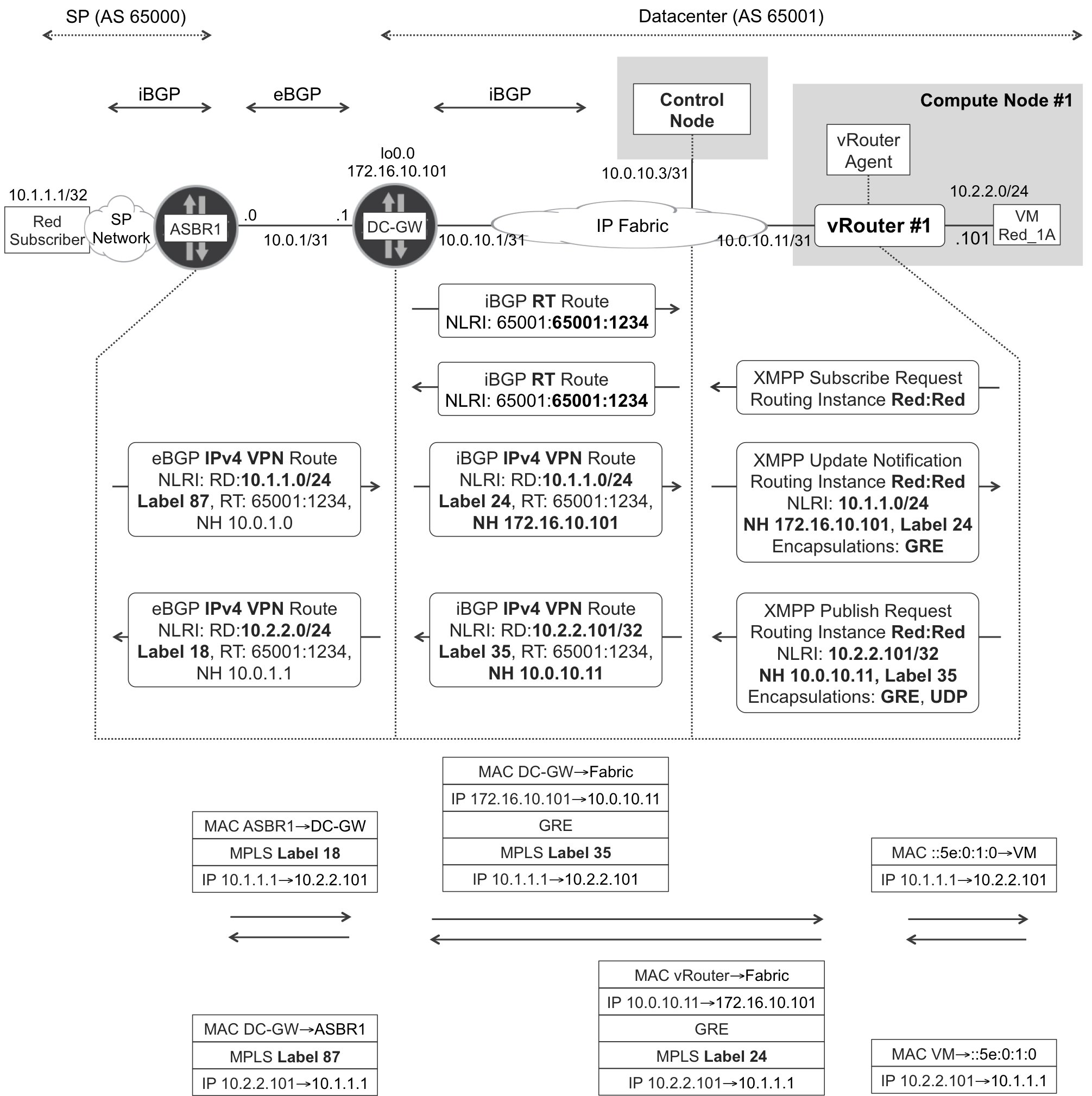
Figure 11-6. XMPP and BGP—L3 overlay at gateway and vRouter
BGP prefixes originated by OpenContrail have an automatically generated RD in the format <ROUTER_ID>:<VPN_ID>, so it supports load balancing of inbound traffic between different vRouters.
OpenContrail advertises its L3 prefixes by listing both GRE (MPLSoGRE) and UDP (MPLSoUDP) as available encapsulations. This information is encoded in the BGP encapsulation extended community.
Note
For detailed coverage of the extended communities that OpenContrail adds to BGP prefixes, search in GitHub for an article on the topic.
In contrast, DC-GW does not include the encapsulation extended community, so OpenContrail assumes that the gateway supports only GRE (MPLSoGRE).
This is a least common denominator decision: MPLSoGRE is used, simply because it is the only encapsulation that both the gateway and OpenContrail (in L3 mode) support.
DC-GW configuration—MPLS-over-GRE
The Junos MPLS-over-GRE tunneling configuration is provided in Example 11-6.
Example 11-6. Dynamic GRE tunnel configuration—DC-GW (Junos)
1     routing-options {
2         dynamic-tunnels {
3             OVERLAY-TUNNELS {
4                 source-address 172.16.10.101;
5                 gre;
6                 destination-networks 10.0.10.0/24;
7     }}}
With this configuration, the local PE (in this case, DC-GW) creates a dynamic GRE interface for each remote address <A> that meets the following two conditions:
-
A received BGP VPN route has as remote BGP next hop <A>.
-
<A> is within the address range specified in line 6.
Let’s look at a dynamic GRE interface, which is pointing to vRouter_1 (Example 11-7).
Example 11-7. Dynamic GRE tunnel—DC-GW (Junos)
user@DC-GW> show route table inet.3 10.0.10.11
inet.3: 4 destinations, 4 routes (4 active, 0 holddown, 0 hidden)

+ = Active Route, - = Last Active, * = Both
10.0.10.11/32      *[Tunnel/300] 3d 15:31:10
                    > via gr-0/0/0.32769

user@DC-GW> show interfaces gr-0/0/0.32769
  Logical interface gr-0/0/0.32769 (Index 376) (SNMP ifIndex 579)
    Flags: Up Point-To-Point SNMP-Traps 0x0
    IP-Header 10.0.10.11:172.16.10.101:47:df:64:0000080000000000
    Encapsulation: GRE-NULL
    Protocol inet, MTU: 1576
    Protocol mpls, MTU: 1564, Maximum labels: 3

user@DC-GW> show route table VRF-Red.inet.0

10.2.2.101/32  *[BGP/170] 09:18:20, localpref 200, from 10.0.10.3
                  AS path: ?, validation-state: unverified
                > via gr-0/0/0.32769, Push 35
There is an interoperability example with IOS XE in the OpenContrail web page.
Communication Between Virtual Networks
Inter-VN connectivity requirements are frequent. For example, the Red subscribers in the upper-left corner of Figure 11-3 might require access to the Blue VMs (Blue_1A and Blue_2A). Or Red VMs might need to communicate to Blue VMs.
Here is a nonexhaustive list on how to address these requirements:
-
Add a new vNIC to the Blue VMs and place the vNIC in the Red VN. This approach solves the connectivity problem, but it’s not very secure. Communication from Blue VMs toward the Red VMs becomes unrestricted.
-
Add a new common RT to both VN Red and Blue in OpenContrail. This automatically leaks prefixes between both VNs. If the policies are conveniently updated in the DC-GW, the VNs are functionally blended into one VN. Again, the connectivity problem is solved, but it is not the best approach in terms of security.
-
Define an OpenContrail policy (Configure→Networking→Policies) that allows traffic between both VNs. This policy is then explicitly applied to both VNs (Configure→Networking→Networks). After it is applied, prefixes are automatically leaked between VN Red and Blue inside OpenContrail. However, RTs are not modified. For this reason, it is necessary to explicitly configure the extranet (see Chapter 3) at the DC-GW to make this leaking effective up to the subscribers. But this has security implications, mind you.
Let’s step back for a moment and briefly talk about policies in OpenContrail. Depending on the security requirements, policies can have a set of unidirectional and/or bidirectional terms. Suppose, for example, that you apply a policy that allows TCP traffic from the Red VN toward the Blue VN. As a result, vRouters become stateful firewalls and they support the creation of flows from Red to Blue but not from Blue to Red.
Note
Control nodes retrieve flow information from vRouter agents for analytics purposes. However, vRouters are empowered to create flows with no intervention from the control nodes. This is very important from the perspective of performance: flow creation is distributed.
Last but not least, the most powerful and secure approach to allow inter-VN communication is to configure Service Function Chains (SFC). This is an SDN best-in-breed approach that lies at the heart of the NFV concept. One of its breakthrough advantages is that you can define SFCs without touching the configuration of the DC-GW. Chapter 12 covers NFV in detail.
Network Virtualization Overlay: L2_L3 Mode
After discussing OpenContrail’s L3 mode, let’s now focus on the L2_L3 mode. Unlike classical PEs, which keep the L3 VRF in a different instance with respect to the L2 EVI, an OpenContrail’s VRF have a dual mode and integrate the L2 and L3 functionalities.
VXLAN Refresher
Chapter 8 introduces the Virtual eXtensible LAN (VXLAN) basic concepts, including its forwarding plane and an example of the control plane (EVPN). Let’s quickly refresh the basics. Any VXLAN Tunnel Endpoint (VTEP) is an edge forwarder (functionally, like a PE). There are basically three types of VTEPs:
-
Hypervisors implementing a VXLAN stack. The VXLAN header is handled by the forwarder component within the hypervisor. VMs just send and receive plain Ethernet frames: they have no VXLAN awareness.
-
ToR switches with a VXLAN stack, providing connectivity to legacy switches, bare-metal servers, and hypervisors, which lack overlay capabilities.
-
PE routers (data center gateways) implementing a VXLAN stack.
As of this writing, VXLAN has three alternative solutions to achieve MAC learning between VTEPs: EVPN, OVSDB, and BUM flooding over IP Multicast. This book considers the last approach as legacy so it only covers EVPN and OVSDB.
VXLAN use cases
VXLAN in SDN cloud architectures is typically used to provide an L2 overlay inside a data center that has an L3 underlay. ToR switches with VXLAN capabilities can also integrate legacy equipment (bare-metal servers, hypervisors, and switches that lack overlay capabilities) into the L2 overlay. Another use case is L2 Data Center Interconnection (DCI). If an application requires L2 connectivity between end systems in geographically distant data centers, it is possible to stretch the L2 overlay across the WAN by using VXLAN.
Note
MPLS-over-X (where X can be MPLS, or UDP, or GRE), also addresses these very same use cases successfully.
Stretching L2 overlays across geographical boundaries is not necessarily a good idea. The best practice is to reduce as much as possible the scope of L2 broadcast domains. Even L2 overlays have a loop risk.
There are several ways to implement DCI, and probably the most popular is depicted in Figure 11-7. In this case, the data center gateway implements EVPN VXLAN toward the local data center, and EVPN MPLS toward the WAN. These two services are stitched at the same L2 instance in the DC-GW.
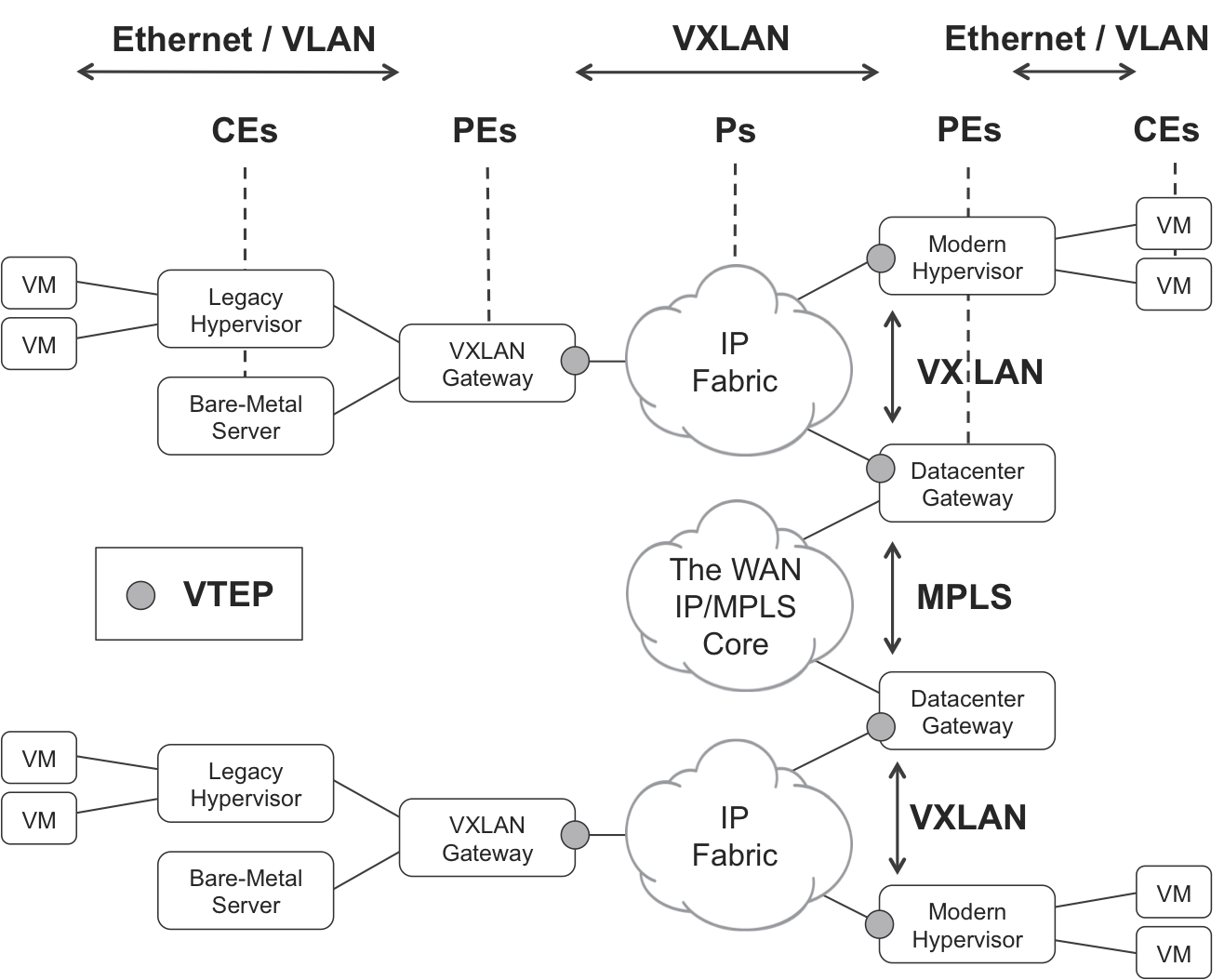
Figure 11-7. VXLAN and VTEPs
Intrasubnet (L2) and Intersubnet (L3) Traffic
In L3-only mode, OpenContrail supports two overlay encapsulations (GRE and UDP) and two address families (RT and IP VPN). Moving to L2_L3 mode, one more encapsulation (VXLAN) and one more BGP address family (EVPN) are added to the list. But these are only applicable to intrasubnet traffic.
In L2_L3 mode, there are two types of traffic: intrasubnet and intersubnet. Remember that a VN is a set of subnets, so intra-VN traffic can either be intrasubnet or intersubnet. For example, if VN Red consists of 10.2.2.0/24 and 10.3.3.0/24:
-
A packet from 10.2.2.101 to 10.2.2.103 is intrasubnet.
-
A packet from 10.2.2.101 to 10.3.3.101 is intersubnet.
Intersubnet traffic follows the same rules that have just been described for L3-only mode. The mechanisms shown in Figure 11-5 and Figure 11-6 are applicable to this case. So let’s focus on intrasubnet traffic. The current specification for EVPN as an NVO (draft-ietf-bess-evpn-overlay) does not allow for a given EVPN MAC/IP route to advertise both a MPLS label and a VNI. It is one or the other. For this reason, OpenContrail advertises EVPN routes that have the following:
-
MPLS label if VXLAN is not the locally preferred encapsulation
-
VNI if VXLAN is the locally preferred encapsulation
Thus, the following examples assume that VXLAN is set as the top preferred encapsulation in OpenContrail configuration. Note that Figure 11-8 provides the network architecture and addressing for the upcoming examples.
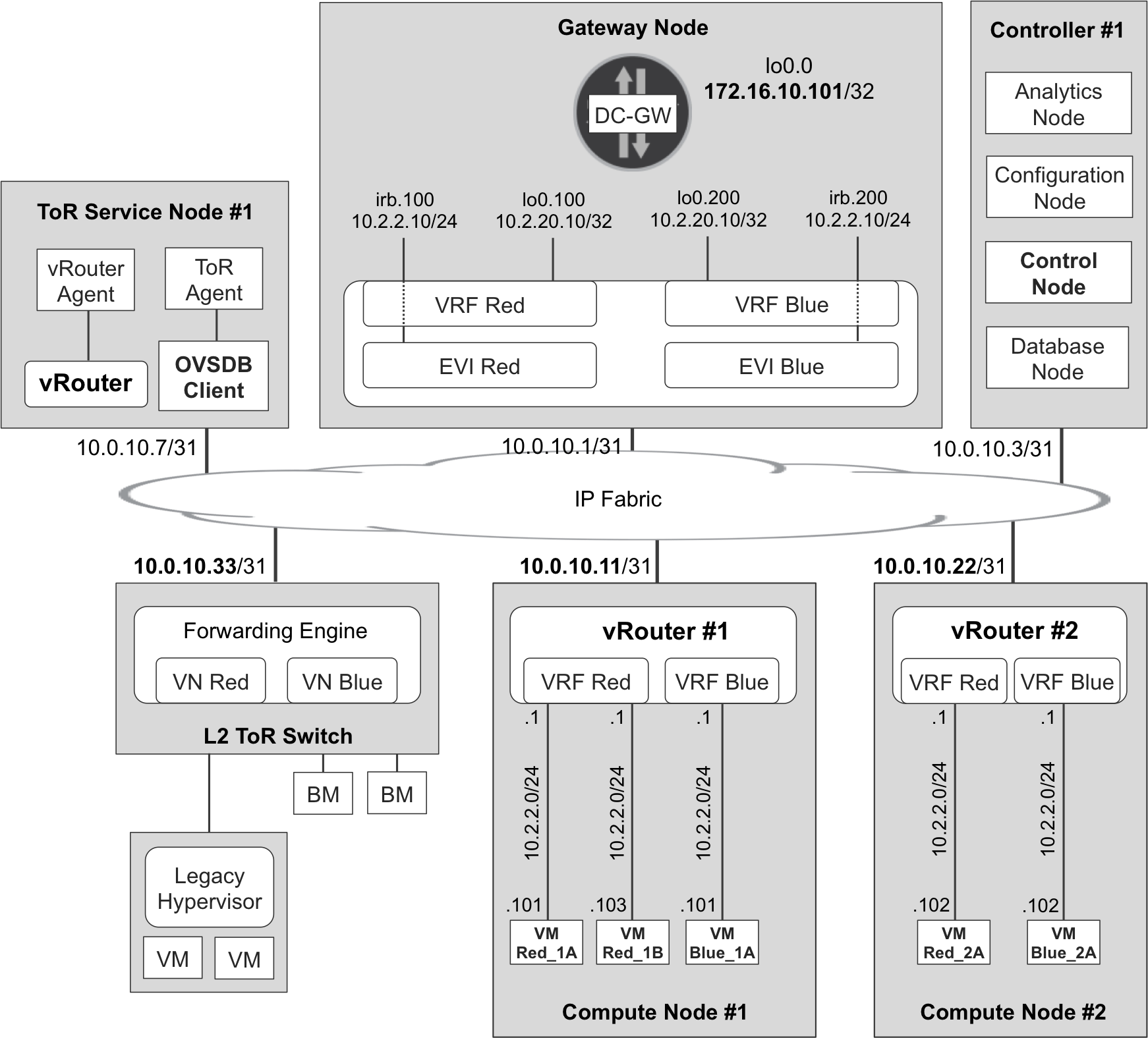
Figure 11-8. Infrastructure and VPN addressing—L2_L3 mode
Interconnecting VMs—IntraSubnet Traffic with VXLAN
The L2_L3 signaling process is shown in Figure 11-9, and it is very similar to the L3 illustration in Figure 11-5, but there are some differences. In L2_L3 mode, three routes are advertised for each vNIC address:
-
IP VPN host address with encapsulation communities GRE and UDP. This is exactly the same route that is advertised in L3 mode (Figure 11-5).
-
EVPN IP/MAC route with encapsulation VXLAN and a VNI (5100, in this example). This is the only route shown in Figure 11-9.
-
EVPN MAC route with encapsulation VXLAN and a VNI (5100, in this example).
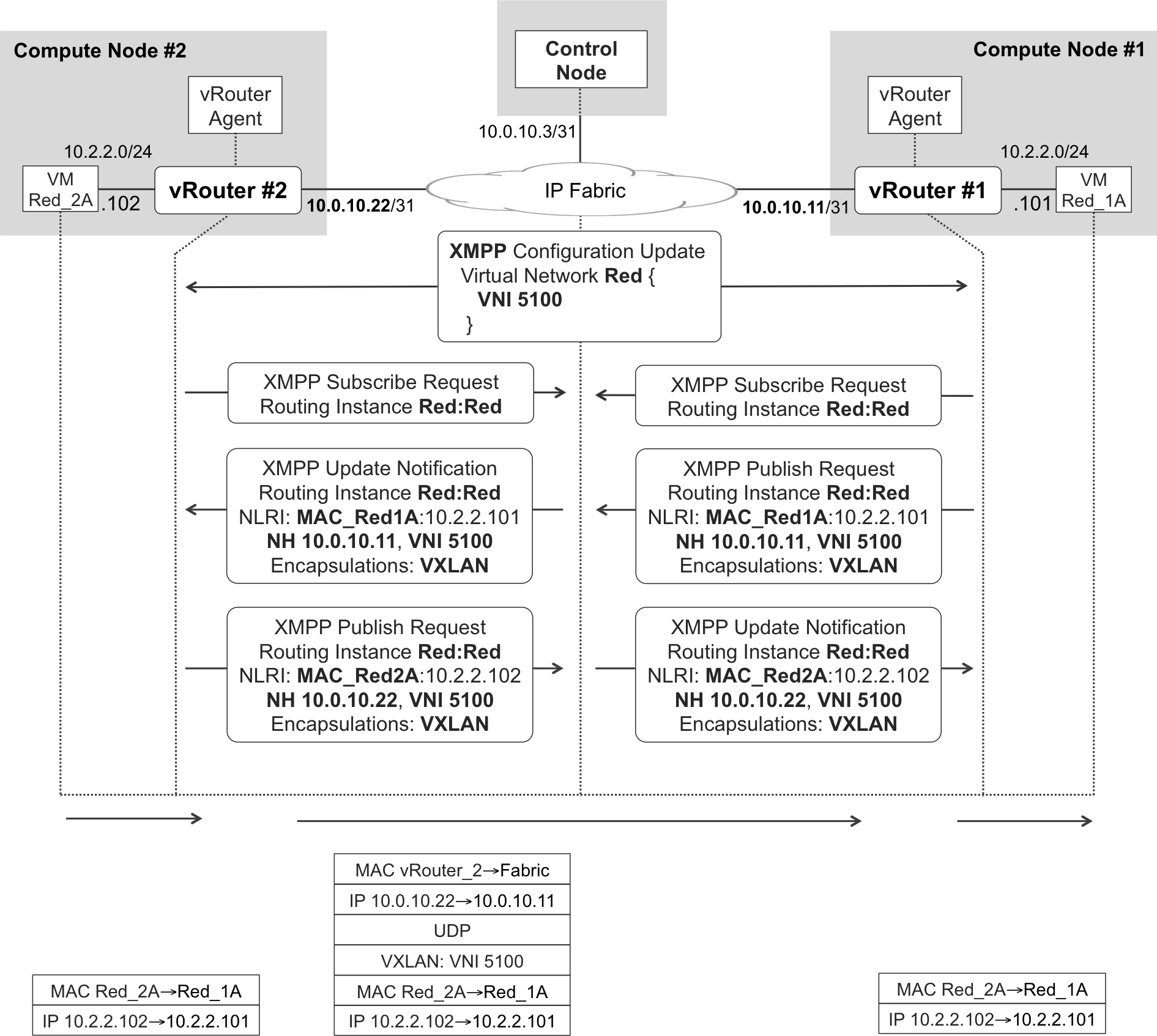
Figure 11-9. XMPP and VXLAN—L2_L3 intrasubnet mode
Remember that EVPN IP/MAC and MAC routes are conceptually similar to ARP and bridge entries—they are just distributed through the control plane. The most relevant information element for intrasubnet traffic forwarding is the EVPN MAC route.
MPLS labels are locally assigned by a vRouter. On the other hand, VNIs are typically configured to the same value on all VTEPs. In OpenContrail, the VNI is a property of the VN, and this is why the control node sends the message shown in Example 11-8 to all the vRouters with at least one tap interface in VN Red.
Example 11-8. XMPP—Configuration update with VN-VNI mapping
<?xml version="1.0"?>
<iq type="set" from="network-control@contrailsystems.com"
    to="default-global-system-config:vrouter_1/config">
  <config>
    <update>
      <node type="virtual-network">
        <name>default-domain:mpls-in-the-sdn-era:Red</name>
        <virtual-network-properties>
          <vxlan-network-identifier>5100</vxlan-network-identifier>
          <forwarding-mode>l2_l3</forwarding-mode>
          <rpf></rpf>
        </virtual-network-properties>
      </node>
    </update>
  </config>
</iq>
The format of the remaining XMPP messages—Subscribe Request, Publish Request, and Update Notification—is very similar to those shown in L3-only mode. Example 11-9 presents an example of how an EVPN MAC/IP route is encoded in XMPP.
Example 11-9. XMPP Publish Request—VM’s vNIC MAC/IP route
<?xml version="1.0"?>
<iq type="set" from="vrouter_1"
    to="[email protected]/bgp-peer" id="pubsub12">
  <pubsub xmlns="http://jabber.org/protocol/pubsub">
    <publish node="25/242/02:4e:a3:72:02:87,10.2.2.101/32">
      <item>
        <entry>
          <nlri>
            <af>25</af>
            <safi>242</safi>
            <ethernet-tag>5100</ethernet-tag>
            <mac>02:4e:a3:72:02:87</mac>
            <address>10.2.2.101/32</address>
          </nlri>
          <next-hops>
            <next-hop>
              <af>1</af>
              <address>10.0.10.11</address>
              <label>5100</label>
              <tunnel-encapsulation-list>
                <tunnel-encapsulation>vxlan</tunnel-encapsulation>
              </tunnel-encapsulation-list>
            </next-hop>
          </next-hops>
          <sequence-number>0</sequence-number>
          <local-preference>100</local-preference>
        </entry>
      </item>
    </publish>
  </pubsub>
</iq>
<iq type="set" from="vrouter_1"
    to="[email protected]/bgp-peer"
    id="collection20">
  <pubsub xmlns="http://jabber.org/protocol/pubsub">
    <collection node="default-domain:mpls-in-the-sdn-era:
                      Red:Red">
      <associate node="25/242/02:4e:a3:72:02:87,10.2.2.101/32"/>
    </collection>
  </pubsub>
</iq>
The VNI is encoded as a <label>. Not surprising: it plays the same role! SAFI 242 is reserved for private use. Because XMPP is used only between control nodes and vRouter agents, using a reserved SAFI is fine. The proper EVPN SAFI (70) is used in the iBGP updates: this is all that matters for interoperability purposes.
BUM traffic flooding
As of this writing, a vRouter (as a VTEP) floods BUM traffic by using an Ingress Replication (IR) mechanism. See the EVPN sections in Chapter 8 for more details. Translated to XMPP, these routes contain <mac>ff:ff:ff:ff:ff:ff</mac>.
VMs take care of ARP resolution. In L2_L3 mode, unlike L3-only mode, vRouters do not perform any proxy-like ARP function for intrasubnet IP addresses. This is the current implementation, but it might change in the future.
vRouter and Gateway Nodes—L2_L3 Mode
Again, as you can see in Figure 11-10, control nodes translate XMPP messages to BGP messages, and vice versa.
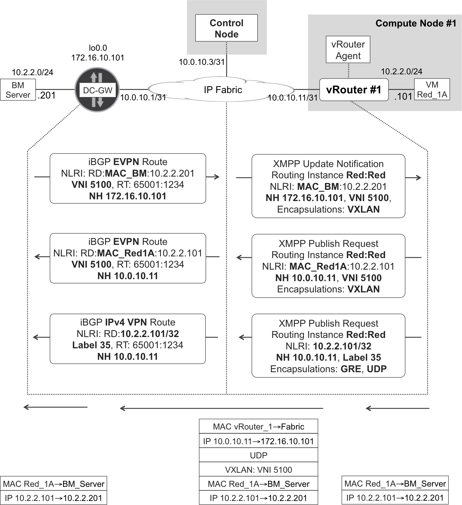
Figure 11-10. XMPP and BGP—L2 overlay at gateway and vRouter
DC-GW can act either as an L2 or an L3 gateway. With regard to the bare-metal (BM) server on the left in Figure 11-10, DC-GW plays the role of an L2 gateway because BM and VM Red_1A are in the same subnet. So, as you might expect from an L2 overlay solution, the original MAC headers are preserved end-to-end.
What if the BM server was in a different subnet than the VM? In this case (not shown in Figure 11-10), DC-GW acts as an L3 gateway, and it should be configured with two different bridge domains:
-
One bridge domain that includes the local Attachment Circuit (AC) connected to the BM server: you can optionally stretch this bridge domain beyond DC-GW by configuring a VXLAN VNI on it, but this VNI must be different from 5100 in this particular example.
-
One bridge domain that is configured with VNI 5100 and therefore is L2 overlay-connected to the VM Red_1A.
Now, DC-GW has two Integrated Routing and Bridging (IRB) interfaces, one linked to each bridge domain. These IRB interfaces make it possible for DC-GW to perform L3 forwarding, the mechanics of which are fully discussed in Chapter 8. This is intersubnet traffic and the original L2 headers are stripped before sending the packets through the overlay tunnel. From a routing perspective, the IP VPN routes for the BM’s and VM’s host prefixes are the ones taken into account. Therefore, for intersubnet traffic, DC-GW is an L3 gateway, and the transport is MPLS-over-GRE (not VXLAN).
As of this writing, the implementation in OpenContrail and in a Junos DC-GW is symmetrical:
- L2_L3 intrasubnet
- EVPN as the control plane and VXLAN as the overlay tunnel; original L2 headers are preserved.
- L2_L3 intersubnet is similar to L3
- IP VPN as the control plane and MPLS-over-GRE as the overlay tunnel (or MPLS over UDP for vRouter-to-vRouter); original L2 headers are stripped.
This symmetry rule has a very specific exception. Imagine an intrasubnet IP flow between a VM and an IRB interface at DC-GW. For example, ping between 10.2.2.101 and 10.2.2.10 (this is DC-GW’s IRB address, as illustrated in Figure 11-8). One IP endpoint of this flow is the IRB interface itself—in other words, it is host traffic from the point of view of DC-GW. In this very specific case, OpenContrail vRouter uses an L2 mechanism (like L2_L3 intrasubnet in the preceding list) while a Junos DC-GW uses a L3 mechanism (like L2_L3 intersubnet in the preceding list). The implementation in IOS XR was not explored.
Integrating Legacy L2 World into the NVO
NVOs are great, but not every OS supports them. As a result, some legacy servers, hypervisors, and switches are not overlay-capable. These legacy devices typically support VLANs only; therefore, they need a gateway to become part of the NVO.
L2 Gateways and OVSDB
There are basically two options for such a legacy device:
-
Connecting the device to an L3 gateway that provides IP termination and assigns the AC to an IP VPN or to the global IP routing table. This is a classic approach.
-
Connecting the device to an L2 gateway that stitches the AC into an overlay L2 VPN—such as VXLAN. Typically, an external service node is also required to handle broadcast traffic like ARP and DHCP.
The first option is IP VPN business as usual. Let’s explore the second option. VXLAN is a common L2 overlay in IP fabrics. Among the different control-plane options available for VXLAN, EVPN is the most scalable and flexible one. However, not every L2 gateway (and not every NVO controller) supports it.
As of this writing, EVPN often coexists with a different control-plane protocol. This protocol is OVSDB. It is a TCP-based protocol defined in RFC 7047, and like EVPN, can propagate MAC learning state through the control plane. The vast majority of NVO solutions in the industry, including OpenContrail, support OVSDB.
OVSDB is very different from BGP (and XMPP). It is easy to see that this protocol comes from the IT world. The controller has a centralized relational database, and each agent has a subset of this database. Both the controller and the agents must be able to modify this database, and the changes must be synchronized.
Figure 11-11 shows BM, a bare-metal server that is connected to an L2 gateway—labeled as L2 ToR. The L2 ToR is a VTEP and also implements an OVSDB server.
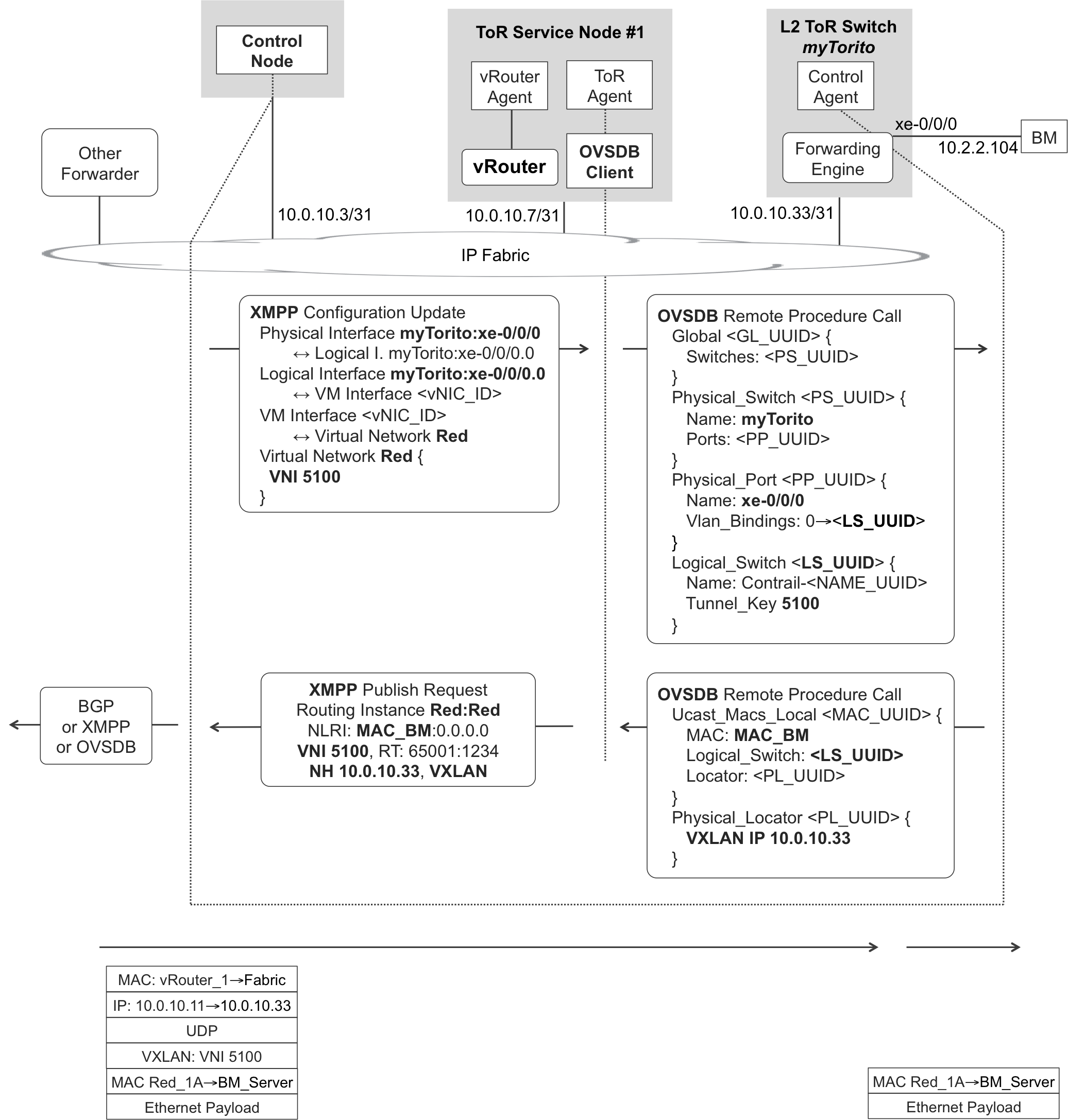
Figure 11-11. XMPP and OVSDB—Extending L2 overlay to BM server
ToR Service Nodes
ToR service nodes (TSN) are part of OpenContrail and they perform two functions through their different software components:
- Control Plane Proxy
- The TSN instantiates one ToR agent for every L2 ToR gateway that supports OVSDB but not EVPN. Each ToR agent speaks XMPP with the control node and implements an OVSDB client that interacts with the L2 ToR device. ToR agents at a TSN basically implement a selective translation function between XMPP and OVSDB.
- Control Packet Proxy
- The TSN also runs one vRouter, but this does not connect VMs. Instead, the vRouter acts as a VTEP that exchanges certain VXLAN-encapsulated control traffic (ARP, DHCP, DNS) with the L2 ToR devices. The vRouter agent at the TSN implements a proxy function. It generates control packets based on the information that it receives from the control node. For example, suppose that the TSN vRouter receives a DHCP discover message—originated by a BM server and VXLAN-tunneled by the L2 ToR toward the TSN’s vRouter. In this case, the vRouter can send the DHCP offer back, based on the information that it has previously received from the control node via XMPP.
From the perspective of both the control node and the vRouter, and regardless of whether the latter is VM-facing or TSN-based, the mechanism to assign an IP to a VM or to a BM server, respectively, is exactly the same. The control node centralizes this information and provides it to the vRouter agent via XMPP.
It is possible to provide TSN active-active redundancy by making the control nodes advertise a floating IP and redirect OVSDB over TCP sessions to the appropriate TSN.
Binding a Bare-Metal Server to the Overlay
If an L2 ToR device supports EVPN, it just needs to establish BGP sessions to the control nodes. Things become more complex if the L2 ToR supports OVSDB but not EVPN. Figure 11-11 shows how OpenContrail integrates—into the VNO—a BM server that is connected to such an L2 ToR.
XMPP signaling
After the ToR-BM link is added on the OpenContrail GUI (Configure→Physical Devices) or on the north-bound RESTful API, control nodes start the signaling.
Example 11-10. XMPP—Configuration update to a TSN vRouter agent
1     <?xml version="1.0"?>
2     <iq type="set" from="network-control@contrailsystems.com"
3         to="default-global-system-config:tsn_1/config">
4     <config>
5       <update>
6         <node type="physical-interface">
7           <name>default-global-system-config:myTorito:xe-0/0/0</name>
8         </node>
9         <node type="logical-interface">
10          <name>default-global-system-config:myTorito:
11                xe-0/0/0:xe-0/0/0.0</name>
12        </node>
13        <link>
14          <node type="physical-interface">
15            <name>default-global-system-config:myTorito:xe-0/0/0</name>
16          </node>
17          <node type="logical-interface">
18            <name>default-global-system-config:myTorito:
19                  xe-0/0/0:xe-0/0/0.0 </name>
20          </node>
21          <metadata type="physical-interface-logical-interface" />
22        </link>
23        <node type="virtual-machine-interface">
24          <name>default-domain:mpls-in-the-sdn-era:
25                e20af8cd-ef70-4608-a3ec-f34eb5018410</name>
26        </node>
27        <link>
28          <node type="logical-interface">
29            <name>default-global-system-config:myTorito:
30                  xe-0/0/0:xe-0/0/0.0</name>
31          </node>
32          <node type="virtual-machine-interface">
33            <name>default-domain:mpls-in-the-sdn-era:
34                  e20af8cd-ef70-4608-a3ec-f34eb5018410
35              </name>
36          </node>
37          <metadata type="logical-interface-virtual-machine-interface">
38        </link>
39      </update>
40    </config>
41    </iq>
The Configuration Update in Example 11-10 is not complete. A selection is shown to illustrate the key idea: OpenContrail internally maps the ToR-BM interface to a VM interface or virtual-machine-interface object (lines 27 through 38). This is very important because the XMPP encoding used for VM interfaces is reused for ToR-BM interfaces.
Let’s see how. Back in Example 11-2 (lines 35 through 59), a genuine VM interface was linked to a VN, an IP address, and a VRF. It’s possible to do exactly the same thing for the VM interface that is associated to a BM server. Following is the additional information that the control node sends to the TSN:
-
The VN that the ToR-BM interface belongs to (Red): this VN is in L2_L3 mode and it has a VNI associated, so the VXLAN encapsulation is known.
-
The VRF that the ToR-BM interface belongs to (Red:Red).
-
The IP address that is preassigned to the BM server. Thus, the TSN knows what IP to offer when the BM sends a DHCP discover packet—and the L2 ToR device encapsulates it in VXLAN toward the TSN.
OVSDB signaling
As its name implies, OVSDB is a protocol used to transfer and synchronize a database between different systems. OVSDB is based on JavaScript Object Notation (JSON). The schema of the hardware_vtep database is documented, and you can easily find it in the OVS (Open vSwitch) website at http://www.openvswitch.org.
You might wonder why OpenContrail internally uses XMPP instead of OVSDB. The reasons are flexibility and performance, especially when a DC-GW is present: XMPP and BGP follow the same structural principles.
In the MPLS analogy, an L2 ToR is seen as a PE, BM servers as CEs, and ToR’s access interfaces as ACs. With the information shown in Example 11-11, the L2 ToR switch called myTorito knows how to integrate its untagged access interface xe-0/0/0.0 into a VXLAN overlay with VNI 5100.
Example 11-11. OVSDB—Integrating a ToR-BM Port in the Overlay
1     "Global":{
2       "587dc36b-09dd-411b-b0e3-44300800d6b9":{
3         "new":{
4           "switches":
5             ["uuid","3841501b-71a6-4f84-97f4-b8aa72ea1723"]
6         }
7       }
8     }
9     "Physical_Switch":{
10      "3841501b-71a6-4f84-97f4-b8aa72ea1723":{
11        "new":{
12          "name":"myTorito",
13          "tunnel_ips":"10.0.10.33",
14          "ports":[
15            "set",[
16              ["uuid","37e69f8a-4c29-413a-b641-a9b420c1548b"],
17            ]
18          ]
19        }
20      }
21    }
22    "Physical_Port":{
23      "37e69f8a-4c29-413a-b641-a9b420c1548b":{
24        "new":{
25          "name":"xe-0/0/0",
26          "vlan_bindings":[
27            "map",[
28              [0,["uuid","26aeb04f-89c7-4c5b-a0d7-c4c9b16aff5c"]]
29            ]
30          ]
31        }
32      }
33    }
34    "Logical_Switch":{
35      "26aeb04f-89c7-4c5b-a0d7-c4c9b16aff5c":{
36        "new":{
37          "name":"Contrail-fd2f3fd7-db4f-4f0a-a5ab-f3800f5348a0",
38          "tunnel_key":5100
39        }
40      }
41    }
Let’s analyze this example from a database perspective. The Global table contains the list of physical L2 ToR devices. More specifically, it contains the list of the Universally Unique Identifier (UUID) of each device. The TSN has the full database, but it only exchanges with a given ToR the section that corresponds to that ToR. In this example, there is only one ToR, whose UUID identifies one entry in the Physical_Switch table (lines 5 and 10 match).
The Physical_Switch table has one entry per physical L2 ToR. Lines 10 through 20 display one single entry, with the following fields:
name- States the L2 ToR’s hostname (myTorito).
tunnel_ips- Specifies the L2 ToR’s VTEP address.
port- Lists the UUIDs of all the access ports that the L2 ToR integrates in the overlay. Each UUID references one entry in the Physical_Port table: lines 16 and 23 match.
The Physical_Port table has one entry per port. Lines 23 through 32 display one single entry, with the following fields:
name- This is the access port in L2 ToR’s vendor-specific terminology. In this example, the L2 ToR is a device running Junos, hence the xe-0/0/0 format. Of course, the format needs to be adapted to the L2 ToR specific vendor, as appropriate.
vlan_bindings- This is a map between per-port access VLANs and logical switches. You can see a logical switch like a separate bridge domain at a given L2 ToR. In this example, the BM port is untagged so there is only VLAN zero and it is mapped to the UUID of an entry in the Logical_Switch table (lines 28 and 35 match).
The Logical_Switch table has one entry per bridge domain. Lines 35 through 40 display one single entry, with the following fields:
name- This is the name of the bridge domain as it has to be configured on the L2 ToR.
tunnel_key- This is the VNI of the bridge domain.
Putting it all together, the OVSDB message in Example 11-11 triggers a configuration change on the L2 ToR. The latter is responsible for translating the standard OVSDB message into a vendor-specific configuration. For example, Example 11-12 shows the resulting change if the L2 ToR device is a QFX Series running Junos.
Example 11-12. Configuration change triggered by an OVSDB message—Junos
1     [edit interfaces]
2     +   xe-0/0/0 {
3     +       encapsulation ethernet-bridge;
4     +       unit 0;
5     +   }
6     [edit vlans]
7     +   Contrail-fd2f3fd7-db4f-4f0a-a5ab-f3800f5348a0 {
8     +       interface xe-0/0/0.0;
9     +       vxlan {
10    +           vni 5100;
11    +       }
12    +   }
The VLAN configured in lines 6 through 12 is actually a bridge domain: it does not even have a vlan-id! Note that Example 11-11 (line 37) and Example 11-12 (line 7) match.
MAC Learning with OVSDB
As shown in Example 11-13 a new entry in a bridge domain’s MAC table is simply a new entry in a certain table inside the hardware_vtep database. As soon as the L2 ToR learns the MAC address of the BM server, it adds a new row to the Ucast_Macs_Local table and propagates the change toward the TSN.
Example 11-13. MAC table entry in an OVSDB message
1     "Ucast_Macs_Local":{
2       "935afb18-23b8-42b2-8691-41342cf56c07":{
3         "new":{
4           "ipaddr":"0.0.0.0",
5           "logical_switch":["uuid",
6                             "26aeb04f-89c7-4c5b-a0d7-c4c9b16aff5c"],
7           "MAC":"00:21:59:c4:1c:ee",
8           "locator":["uuid","0d42b081-e569-4cec-91e3-ff4e92813e9f"]
9         }
10      }
11    }
12    "Physical_Locator":{
13      "0d42b081-e569-4cec-91e3-ff4e92813e9f":{
14        "new":{
15          "dst_ip":"10.0.10.33",
16          "encapsulation_type":"vxlan_over_ipv4"
17        }
18      }
19    }
Putting it all together again, the L2 ToR switch is telling the TSN that the BM server’s MAC address (line 7) is reachable at the ToR’s VTEP address (line 15) via VXLAN (line 16). And, according to the Logical_Switch table in Example 11-11, with VNI 5100.
Let’s reread the message from a database perspective.
The Ucast_Macs_Local table has one entry for each MAC address of a device that is locally connected on an access port. Lines 2 through 9 display one single entry, with the following fields:
logical_switch- This is the UUID of the logical switch (or bridge domain). Example 11-13 (line 6) matches the logical switch in Example 11-11 (lines 35 through 40). This is a VXLAN domain with VNI 5100.
locator- This is the UUID of an entry in the Physical_Locator table.
The Physical_Locator table has one entry for each local or remote VTEP. Lines 13 through 18 display one single entry, with the following columns:
dst_ip- This is L2 ToR myTorito’s local VTEP address.
encapsulation_type- This is (surprise!) VXLAN-over-IPv4.
As you can see, lines 8 and 13 in Example 11-13 match.
There is another table called Umacs_Macs_Remote for the MAC addresses that the L2 ToR learns from the TSN. Logically, a MAC that is local from the perspective of an L2 ToR device is by definition remote from the perspective of another L2 ToR device. So, these entries are moved around between tables depending on the L2 ToR to which the TSN is talking.
Example 11-14 demonstrates how the resulting MAC table looks in a QFX Series running Junos.
Example 11-14. MAC table with local and remote (OVSDB) entries—Junos
1     root@QFX> show ethernet-switching table
2
3     MAC flags (S - static MAC, D - dynamic MAC, O - ovsdb MAC)
4
5     Ethernet switching table : 3 entries, 1 learned
6     Routing instance : default-switch
7         Vlan          MAC                 MAC      Age    Logical
8         name          address             flags           interface
9         Contrail-fd2f3fd7-db4f-4f0a-a5ab-f3800f5348a0
10                      00:21:59:c4:1c:ee   D        -      xe-0/0/0.0
11        Contrail-fd2f3fd7-db4f-4f0a-a5ab-f3800f5348a0
12                      02:75:fa:14:5a:07   SO       -      vtep.32769
13        Contrail-fd2f3fd7-db4f-4f0a-a5ab-f3800f5348a0
14                      02:1d:1e:10:74:ad   SO       -      vtep.32770
Lines 9 through 10 show the entry associated to the local BM server’s MAC address. It corresponds to a row in the Umacs_Macs_Local table (Example 11-13, line 7).
The following two MAC entries correspond to entries in the Umacs_Macs_Remote table:
-
Lines 11 and 12 show the MAC address of VM Red_1A, which is reachable through vRouter_1 acting as a VTEP.
-
Lines 13 and 14 show the MAC address of the remote BM server that is connected to the DC-GW (see Figure 11-10, in the upper-left corner). Remember that in this case, the DC-GW is acting as a VTEP, but its control plane is EVPN and not OVSDB.
As you can see, the vtep.<#> tunneling interface is different on each of the two remote entries. Indeed, the overlay tunneling headers differ because the remote VTEPs are not the same: vRouter_1 versus DC-GW.
Bare-Metal Servers and OVSDB—the Forwarding Plane
Intrasubnet known unicast traffic is forwarded as shown at the bottom of Figure 11-11. Traffic is directly exchanged between the VTEPs by using standard VXLAN encapsulation. The TSN stays off the forwarding path.
Note
Although the control plane is complex, with several protocols involved, the forwarding plane is very similar: VXLAN everywhere.
How about intersubnet known unicast traffic? The BM servers need to have a default gateway or static route pointing to the DC-GW. The latter performs intersubnet routing through its IRB interfaces, the details of which are simply beyond the scope of this book.
Unknown unicast traffic is regulated by the OpenContrail VN configuration: it can either be dropped or flooded. In the latter case, the information about remote VTEPs is kept in the table Mcast_Macs_Remote. The corresponding entries have MAC “unknown-dst”. Because flooding typically involves IR toward several remote VTEPs, this table has a locator_set rather than a single locator.
Finally, broadcast traffic in OVSDB environments relies on the TSN to perform the replication. This is especially important for ARP and DHCP, as discussed earlier in this chapter. On the other hand, IR of broadcast frames is definitely an option for L2 gateways that support EVPN.