
Chapter 17. Scaling MPLS Services
Chapter 16 discusses different methods for scaling IP/MPLS transport. Unfortunately, in order to design large, scalable networks, it is often not enough to scale the transport. As the next step, you will learn about different design models to scale MPLS services.
The general problem with MPLS service scaling is that you can have a network device, which supports a limited number of routes (in L3VPN deployments), limited number of MAC addresses (in VPLS or EVPN deployments), limited number of features supported (e.g., no support for L3VPN, no support for VPLS/EVPN), and so on. To alleviate all of those problems, the MPLS service itself must be designed in a scalable manner.
This chapter presents some typical architectural models to scale L3 MPLS services. More specifically, the two examples used here are: Default Route Hierarchical L3VPN and PWHE-based Hierarchical L3VPN. However, you can port many of the ideas presented here to other MPLS services. These examples are inspired on the Mobile Backhaul (MBH) use case.
Hierarchical L3VPN
The network topology used for the discussion of service scaling will be basically the same as the multidomain topology described in Chapter 16. For reference, this topology is presented in Figure 17-1.
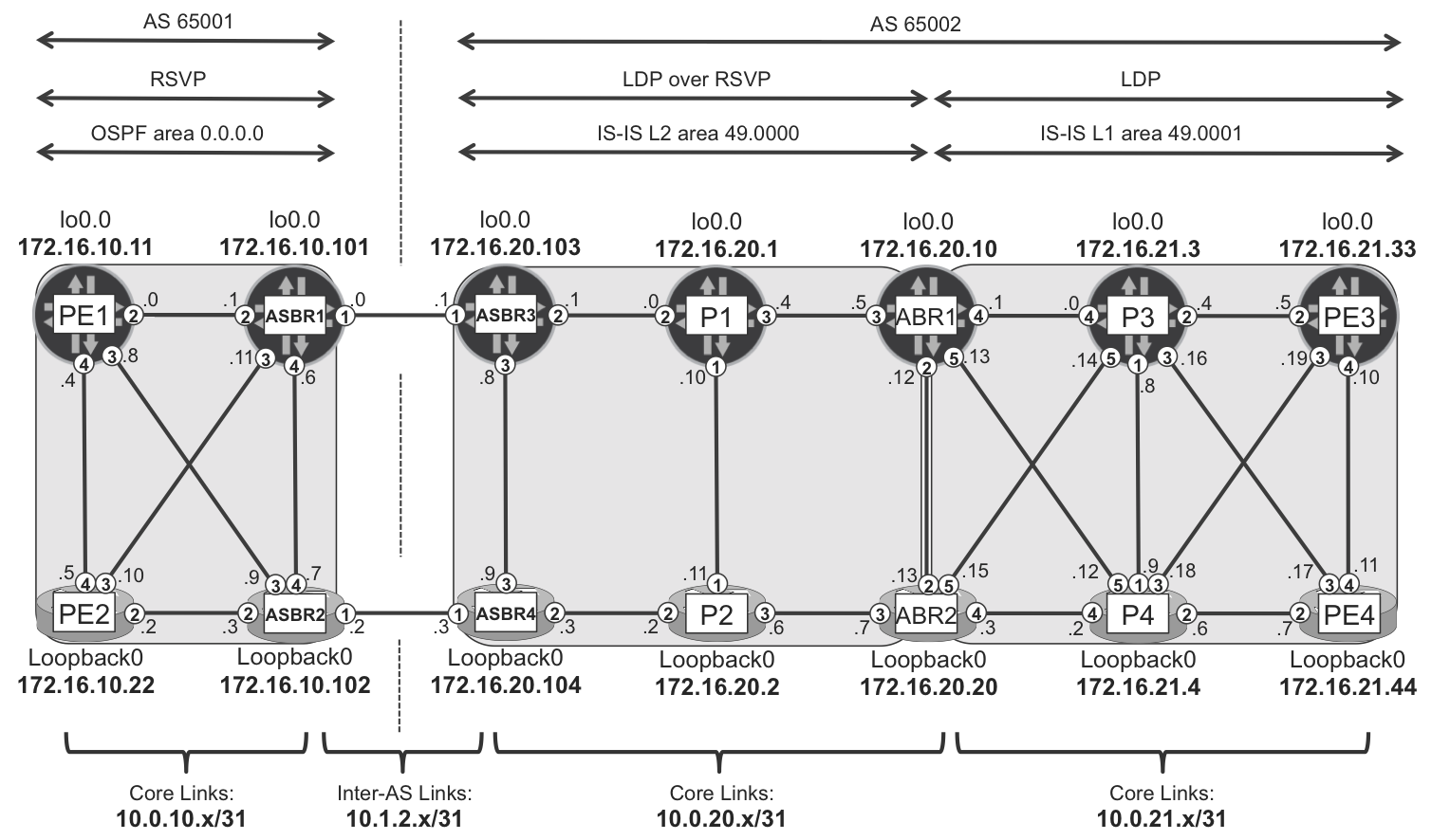
Figure 17-1. Multidomain topology
To create a meaningful basis for a discussion on service scaling, in addition to CE-less VPN-A (built in Chapter 16), VPN-B (with CE) extends the topology. CEs are connected to PE routers as outlined in Figure 17-2. Different CEs use various PE-CE protocols (eBGP, IS-IS, OSPF, VRRP) to connect to PE. The details of PE-CE configurations, however, are not discussed here. The basics of L3VPN and VPLS service are covered in Chapter 3 and Chapter 7.
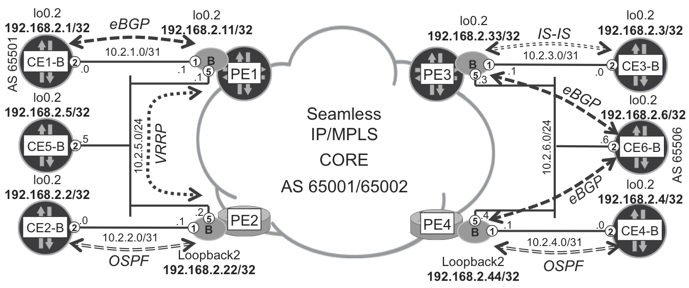
Figure 17-2. VPN-B topology
As in many of the earlier chapters, the physical CE devices are virtualized with routing instances (virtual routers, so-called VRF lite) to create one virtual CE per [physical CE, VPN] pair. In this sense, throughout this chapter there will be further virtual CE devices in addition to those shown in Figure 17-2, as new L3VPN instances are added to the architectural model.
Let’s capture the current state of the network by examining the total number of prefixes in VRF-B, as shown in Example 17-1 and Example 17-2.
Example 17-1. VRF-B prefix state on PE1 (Junos)
juniper@PE1> show route summary
(...)
VRF-B.inet.0: 19 destinations, 39 routes (19 active, ...)
              Direct:      3 routes,      3 active
               Local:      3 routes,      3 active
                 BGP:     32 routes,     12 active
              Static:      1 routes,      1 active
(...)
Example 17-2. VRF-B prefix state on PE2 (IOS XR)
RP/0/0/CPU0:PE2#show route vrf VRF-B summary
Route Source        Routes     Backup     Deleted     Memory(bytes)
connected           2          1          0           420
local               3          0          0           420
local VRRP          0          0          0           0
ospf VRF-B          1          0          0           140
bgp 65001           11         0          0           1540
dagr                0          0          0           0
static              1          0          0           140
Total               18         1          0           2660
On PE1, VRF-B contains routes to 19 destinations, whereas on all other PEs, there are routes to only 18 (PE3 and PE4 are omitted here to save space). This small difference is caused by the fact that PE1 is a Virtual Router Redundancy Protocol (VRRP) master, thus the additional route (VIP address) is present in VRF-B on that PE. However, as it relates to the overall discussion about L3VPN service scaling, this small discrepancy is irrelevant.
You can imagine that in large-scale deployments, the number of prefixes in VRF-B could be very large, not just the 18 or 19 shown in the example. Depending on the platform used as the PE, the number could be too large. In the subsequent sections of this chapter, architectural models to minimize that number are presented.
To make a meaningful comparison between different architectural models, for each model discussed, additional service instances (L3VPN) will be created. Multiple models running in parallel will give you the opportunity to directly compare advantages and disadvantages of each model. Because, unfortunately, nothing is for free, to make the design more scalable, you might need to give up some other aspects. For example, you might need to choose between design complexity and failover behavior during various network failures.
Default Route L3VPN Model
The idea behind the Default Route L3VPN model is very simple:
-
Create VRFs somewhere higher in the network hierarchy on more powerful routers. Let’s call these routers Virtual Hub PEs (V-hubs). These are somewhere deeper in the network infrastructure. V-hubs should be capable of holding all VPN routes for selected VPNs. Depending on the required scale, selected VPNs could mean all VPNs, or just a subset of all VPNs. Typically V-hubs are routers sitting in the aggregation layer in the overall network design.
-
Within each VPN, advertise the default route from each VRF on the V-hub toward less powerful routers farther down in the network hierarchy. Let’s call such routers Virtual Spoke PEs (V-spokes). They are closer to the end user. V-spokes do not scale well, thus, within each locally configured VPN, it will receive only default route with the next hop pointing to a V-hub. The advantage of a V-spoke in such a mode is usually low price, small form factor, low power consumption, and so on, which makes it the preferred choice for mass deployment in large quantities. Typically, V-spokes are routers sitting in the access layer in the overall network design.
The idea is not new. If you look carefully, you’ll see that a similar idea was demonstrated in Chapter 16. For example, ABR1 and ABR2 routers advertise the default route (in a global routing table) toward lower-layer routers (P3, P4, PE3, and PE4) using IS-IS protocol and suppress all other (IS-IS L2) prefixes. The main difference is that previously this model was applied to a global routing table, whereas now it is applied to multiple VPN routing tables. So, the concept is very similar, but the implementation details, of course, differ. The concept is described in RFC 7024 - Virtual Hub-and-Spoke in BGP/MPLS VPNs.
An example of Default Route L3VPN topology is presented in Figure 17-3.
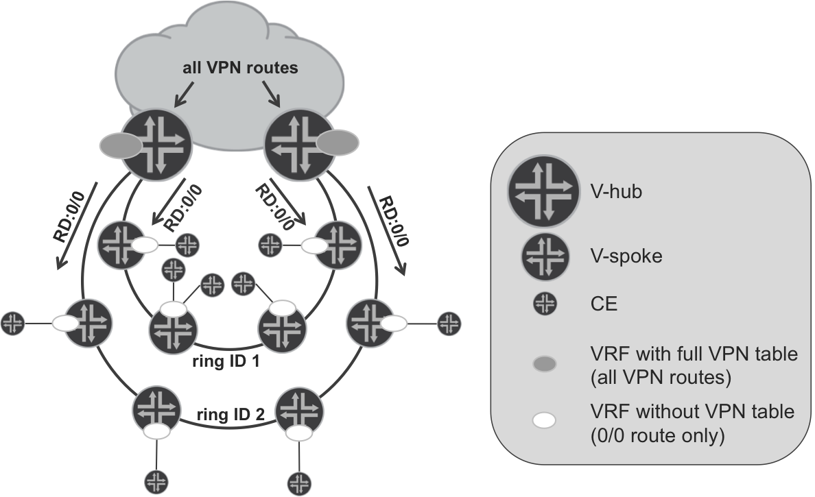
Figure 17-3. The default route L3VPN model
As mentioned previously, you typically could use such a design when a large number of low-end devices (feature-rich but with low scale) are deployed. One typical example could be a Mobile Backhaul (MBH) network, especially in 4G or 5G deployments. In those deployments, the size of the cells (the area covered by a single eNodeB) is relatively small, which naturally increases the overall number of required eNodeBs. This, in turn, is reflected in the large number of access ports (and thus the number of access devices) required from a networking perspective to connect all of those eNodeBs.
As outlined in Figure 17-3, V-spokes (access devices) are typically attached to V-hubs (aggregation devices) via semiclosed rings. Depending on the actual design, multiple VRFs can be created on each V-spoke (Figure 17-3 shows only one). In turn, you could connect multiple CE devices (e.g., eNodeBs) to each V-spoke. V-spokes advertise their locally learned (from locally connected CE devices) VPN prefixes to the V-hubs. In the opposite direction, V-hubs advertise only the default route for each VPN. The end result is that each VRF on V-spoke contains only local CE prefixes and the default route from the V-hubs. For redundancy, both V-hubs terminating access semi-rings are injecting the default route in each VPN. That should result in significantly fewer prefixes in each VRF, compared to nonhierarchical VPN design.
It is important to mention that on V-hubs the VRFs don’t need to be attached to any CE. Thus, it’s possible that no interfaces will be included in those VRFs. The main purpose of VRFs created on V-hubs is to collect all VPN prefixes for each VRF as well as to aggregate prefixes in each VRF via the default route advertised to V-spokes. Later, V-spokes will send packets using the default route. Those packets will arrive to VRFs on V-hubs, where IP lookup (within the VRF) must take place in order to determine further the forwarding path. As is discussed in Chapter 3, IP lookup inside the VRF is not the default behavior (neither for Junos, nor for IOS XR), and you need to explicitly enable it.
You might also see some similarities with the Inter-AS Option B + Local VRF model described in Chapter 9:
-
VRFs typically do not necessarily have local CEs attached.
-
Packets arrive to the VRF as labeled packets.
-
IP lookup is performed inside the VRF for those labeled packets.
-
ASBR in the Inter-AS Option B + Local VRF model acts as kind of an inline RR, reflecting VPN prefixes between multiprotocol iBGP and multiprotocol eBGP neighbors. In a hierarchical L3VPN model, the V-hub reflects prefixes between two multiprotocol iBGP neighbors.
-
Next-hop self is performed when VPN routes are reflected by ASBR in an Inter-AS Option B + Local VRF model. In a hierarchical L3VPN model, a similar result is achieved by advertising the VPN default route, which also uses a next hop that is local to V-hub.
Detailed routing model
To verify this theory in practice, OSPF area 0 (ASBR1, ASBR2, PE1, and PE2) and IS-IS area 49.0001 (ABR1, ABR2, PE3, and PE4) in Figure 17-1 are each functionally—even if not topologically—equivalent to one of the rings in Figure 17-3.
To illustrate the hierarchical L3VPN model, let’s create a new VPN-C in the sample interdomain topology used previously. ASBR1 and ASBR2 are acting as V-hubs for PE1 and PE2, which are deployed in a V-spoke role. Similarly, on the other side of the topology, ABR1 and ABR2 are V-hubs, whereas PE3 and PE4 are V-spokes. The overall design for VRF-C is illustrated in Figure 17-4.
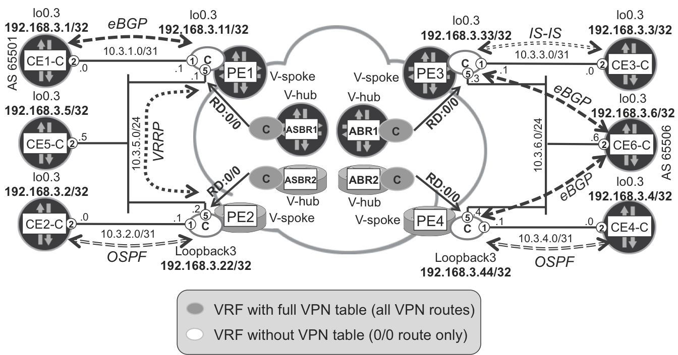
Figure 17-4. VPN-C topology
The configuration of the VRF-Cs on V-spokes is standard; there is nothing specific here. On the V-hubs (ASBR1, ASBR2, ABR1, and ABR2), however, you do not need to configure the PE-CE interfaces in VRF-C. Additionally, within VRF-C on V-hubs, you configure aggregate default discard route with standard community attached. The community will be used to restrict advertisement of this default route to V-spokes only. For reference, Example 17-3 and Example 17-4 present sample Junos and IOS XR configurations, respectively. ABR1 and ABR2 have similar configurations.
Example 17-3. VRF-C configuration on V-hub—ASBR1 (Junos)
routing-instances {
    VRF-C {
        instance-type vrf;
        route-distinguisher 172.16.10.101:103;
        vrf-target target:65000:1003;
        routing-options {
            aggregate {
                route 0.0.0.0/0 {
                    community 65000:41999;
                    discard;
}}}}}
Example 17-4. VRF-C configuration on V-hub—ASBR2 (IOS XR)
vrf VRF-C
 address-family ipv4 unicast
  import route-target
   65000:1003
  !
  export route-target
   65000:1003
!
community-set CM-VPN-DEFAULT-ROUTE
  65000:41999
end-set
!
route-policy PL-VPN-DEFAULT-ROUTE
  set community CM-VPN-DEFAULT-ROUTE
  set origin incomplete
end-policy
!
router bgp 65001
 vrf VRF-C
  rd 172.16.10.102:103
  address-family ipv4 unicast
   aggregate-address 0.0.0.0/0 as-set route-policy PL-VPN-DEFAULT-ROUTE
!
To maintain consistency, in IOS XR, you set the origin attribute explicitly to incomplete (this is the default in Junos). Additionally, you configure the IOS XR V-hub to attach a full AS_SET to the advertised aggregated default route (which, again, is the default in Junos).
V-hubs act as VPN RRs. Until now, there was no inbound or outbound BGP policy attached for IPv4 VPN address families. This must change, because the V-hub role is to advertise the default route only to V-spokes, not reflect routes. In the other direction, upstream (as well as between two V-hubs), routes received from V-spokes should be reflected, but the default route should not be sent.
Thus, you must implement the VPN downstream, VPN upstream, and VPN RR BGP outbound policy on V-hubs. To make it possible to compare between standard VPN (VPN-B) and the default route VPN (VPN-C), those policies will affect only VPN route distribution for VPN-C, as demonstrated in Example 17-5. Typically, on real-life small-scale V-spokes, all VPNs would be implemented in the default route L3VPN model.
Example 17-5. IPv4 VPN outbound BGP policies on ASBR1 (Junos)
protocols {
    bgp {
        group iBGP-DOWN:LU+VPN {
            export [ PL-BGP-LU-DOWN-EXP PL-BGP-VPN-DOWN-EXP ];
        }
        group eBGP-UP:VPN {
            export [ PL-BGP-LU-UP-EXP PL-BGP-VPN-UP-EXP ];
        }
        group iBGP-RR:LU+VPN {
            export [ PL-BGP-LU-RR-EXP PL-BGP-VPN-RR-EXP ];
}}}
policy-options {
    policy-statement PL-BGP-VPN-DOWN-EXP {
        term LOCAL-DEFAULT-ROUTE {
            from {
                family inet-vpn;
                community CM-VPN-DEFAULT-ROUTE;
            }
            then accept;
        }
        term VRF-C {
            from {
                family inet-vpn;
                community RT-VPN-C;
            }
            then reject;
        }
        from family inet-vpn;
        then accept;
    }
    policy-statement PL-BGP-VPN-UP-EXP {
        term LOCAL-DEFAULT-ROUTE {
            from {
                family inet-vpn;
                community CM-VPN-DEFAULT-ROUTE;
            }
            then reject;
        }
        from family inet-vpn;
        then accept;
    }
    policy-statement PL-BGP-VPN-RR-EXP {
        term LOCAL-DEFAULT-ROUTE {
            from {
                family inet-vpn;
                community CM-VPN-DEFAULT-ROUTE;
            }
            then reject;
        }
        from family inet-vpn;
        then accept;
    }
    community CM-VPN-DEFAULT-ROUTE members 65000:41999;
    community RT-VPN-C members target:65000:1003;
}
You can see the definition of the PL-BGP-LU-*-EXP policies in Example 16-16.
Example 17-6. IPv4 VPN outbound BGP policies on ASBR2 (IOS XR)
extcommunity-set rt RT-VPN-C
  65000:1003
end-set
!
route-policy PL-BGP-VPN-DOWN-EXP
  if community matches-any CM-VPN-DEFAULT-ROUTE then
    done
  elseif extcommunity rt matches-any RT-VPN-C then
    drop
  endif
  pass
end-policy
!
route-policy PL-BGP-VPN-UP-EXP
  if community matches-any CM-VPN-DEFAULT-ROUTE then
    drop
  endif
  pass
end-policy
!
route-policy PL-BGP-VPN-RR-EXP
  if community matches-any CM-VPN-DEFAULT-ROUTE then
    drop
  endif
  pass
end-policy
!
router bgp 65001
 !
 neighbor-group iBGP-DOWN:LU_VPN
  address-family vpnv4 unicast
   route-policy PL-BGP-VPN-DOWN-EXP out
 !
 neighbor-group eBGP-UP:VPN
  address-family vpnv4 unicast
   route-policy PL-BGP-VPN-UP-EXP out
 !
 neighbor-group iBGP-RR:LU_VPN
  address-family vpnv4 unicast
   route-policy PL-BGP-VPN-RR-EXP out
!
There is one important difference between applying BGP policies in Junos and IOS XR, as discussed in “Multiprotocol BGP policies”.
-
In IOS XR, policies are applied separately for each address family.
-
In Junos, one single BGP policy chain applies to all the address families signaled in the session. That’s why the policies defined in Example 17-5 use the
from family inet-vpnclause; this way, the IP LU prefixes are unaffected.
Now, it is time for verification. Let’s look at the sizes of VRF routing tables.
Example 17-7. VRF-C prefix state on PE1 (Junos)
juniper@PE1> show route summary
(...)
VRF-C.inet.0: 9 destinations, 11 routes (9 active, ...)
              Direct:      3 routes,      3 active
               Local:      3 routes,      3 active
                 BGP:      4 routes,      2 active
              Static:      1 routes,      1 active
Example 17-8. VRF-C prefix state on PE2 (IOS XR)
RP/0/0/CPU0:PE2#show route vrf VRF-C summary
Route Source        Routes     Backup     Deleted     Memory(bytes)
connected           2          1          0           420
local               3          0          0           420
ospf VRF-C          1          0          0           140
static              1          0          0           140
bgp 65001           1          0          0           140
dagr                0          0          0           0
Total               8          1          0           1260
If you compare these to Example 17-1 and Example 17-2, which show that state for nonoptimized VPN, you can see the decrease in the number of prefixes. Now, there are 10 fewer prefixes. Note that PE1 has more BGP prefixes due to the access eBGP PE-CE session. Let’s have a look at the actual routing tables.
Example 17-9. VRF-C routing table on PE1 (Junos)
juniper@PE1> show route table VRF-C.inet.0 active-path terse
VRF-C.inet.0: 9 destinations, 11 routes (9 active, ...)
+ = Active Route, - = Last Active, * = Both

A V Destination      P Prf  Metric 1    Next hop   AS path
* ? 0.0.0.0/0        B 170       100               65002 {65506} ?
* ? 10.3.1.0/31      D   0              >ge-2/0/1.3
* ? 10.3.1.1/32      L   0               Local
* ? 10.3.5.0/24      D   0              >ge-2/0/5.3
* ? 10.3.5.1/32      L   0               Local
* ? 10.3.5.254/32    L   0               Local
* ? 192.168.3.1/32   B 170       100               65501 I
* ? 192.168.3.5/32   S   5              >10.3.5.5
* ? 192.168.3.11/32  D   0              >lo0.3
Example 17-10. VRF-C routing table on PE2 (IOS XR)
RP/0/0/CPU0:PE2#show route vrf VRF-C
(...)
B*   0.0.0.0/0 [200/0] via 172.16.10.101 (nexthop in vrf default)
C    10.3.2.0/31 is directly connected, 1w0d, Gi0/0/0/1.3
L    10.3.2.1/32 is directly connected, 1w0d, Gi0/0/0/1.3
C    10.3.5.0/24 is directly connected, 1w0d, Gi0/0/0/5.3
L    10.3.5.2/32 is directly connected, 1w0d, Gi0/0/0/5.3
O    192.168.3.2/32 [110/1001] via 10.3.2.0, 1d02h, Gi0/0/0/1.3
S    192.168.3.5/32 [1/0] via 10.3.5.5, 1w0d
L    192.168.3.22/32 is directly connected, 1w0d, Loopback3
As expected, there is a default route pointing to V-hub (ASBR1) and routes associated with locally connected CE devices (CE1-C, CE5-C) only. Remote VPN-C routes (CE2-C, CE3-C, CE4-C, and CE6-C) are not present. Routing tables on other PE routers look similar.
Full VRF routing tables are now available on V-hubs, as shown in Example 17-11 and Example 17-12. As expected, there is one aggregate (Junos) or BGP generated, based on aggregate-address (IOS XR) default discard route, six PE-CE link routes, six CE loopbacks, and four PE VRF loopbacks. There are no local/connected/direct routes, because no local interface is connected to those VRFs. VRF routing tables on remaining V-hubs look similar.
Example 17-11. VRF-C routing table on ASBR1 (Junos)
juniper@ASBR1> show route table VRF-C.inet.0 active-path | match "*"
+ = Active Route, - = Last Active, * = Both
0.0.0.0/0       *[Aggregate/130] 5d 21:37:39
10.3.1.0/31     *[BGP/170] 10:59:25, from 172.16.10.11
10.3.2.0/31     *[BGP/170] 13:37:36, MED 0, from 172.16.10.22
10.3.3.0/31     *[BGP/170] 23:58:34, from 172.16.20.1
10.3.4.0/31     *[BGP/170] 13:29:16, from 172.16.20.1
10.3.5.0/24     *[BGP/170] 10:59:25, from 172.16.10.11
10.3.6.0/24     *[BGP/170] 23:58:34, from 172.16.20.1
192.168.3.1/32  *[BGP/170] 1d 10:59:25, from 172.16.10.11
192.168.3.2/32  *[BGP/170] 1d 13:37:34, MED 1001, from 172.16.10.22
192.168.3.3/32  *[BGP/170] 23:58:34, from 172.16.20.1
192.168.3.4/32  *[BGP/170] 1d 13:29:16, from 172.16.20.1
192.168.3.5/32  *[BGP/170] 1d 10:59:25, from 172.16.10.11
192.168.3.6/32  *[BGP/170] 23:58:34, from 172.16.20.1
192.168.3.11/32 *[BGP/170] 1d 10:59:25, from 172.16.10.11
192.168.3.22/32 *[BGP/170] 1d 13:37:36, MED 0, from 172.16.10.22
192.168.3.33/32 *[BGP/170] 23:58:34, from 172.16.20.1
192.168.3.44/32 *[BGP/170] 1d 13:29:16, from 172.16.20.1
Example 17-12. VRF-C routing table on ASBR2 (IOS XR)
RP/0/0/CPU0:ASBR2#show route vrf VRF-C
(...)
B* 0.0.0.0/0 [200/0] via 0.0.0.0, 6d11h, Null0
B 10.3.1.0/31 [200/0] via 172.16.10.11 (nexthop in vrf default)
B 10.3.2.0/31 [200/0] via 172.16.10.22 (nexthop in vrf default)
B 10.3.3.0/31 [20/0] via 172.16.21.33 (nexthop in vrf default)
B 10.3.4.0/31 [20/0] via 172.16.21.44 (nexthop in vrf default)
B 10.3.5.0/24 [200/0] via 172.16.10.11 (nexthop in vrf default)
B 10.3.6.0/24 [20/0] via 172.16.21.33 (nexthop in vrf default)
B 192.168.3.1/32 [200/0] via 172.16.10.11 (nexthop in vrf default)
B 192.168.3.2/32 [200/1001] via 172.16.10.22 (nexthop in vrf default)
B 192.168.3.3/32 [20/0] via 172.16.21.33 (nexthop in vrf default)
B 192.168.3.4/32 [20/0] via 172.16.21.44 (nexthop in vrf default)
B 192.168.3.5/32 [200/0] via 172.16.10.11 (nexthop in vrf default)
B 192.168.3.6/32 [20/0] via 172.16.21.33 (nexthop in vrf default)
B 192.168.3.11/32 [200/0] via 172.16.10.11 (nexthop in vrf default)
B 192.168.3.22/32 [200/0] via 172.16.10.22 (nexthop in vrf default)
B 192.168.3.33/32 [20/0] via 172.16.21.33 (nexthop in vrf default)
B 192.168.3.44/32 [20/0] via 172.16.21.44 (nexthop in vrf default)
Achieving end-to-end connectivity in the Junos plane
Routing information seems to be perfect, so now, let’s verify the connectivity between CE routers, for example between CE1-C and CE3-C.
Example 17-13. Failed ping from CE1-C to CE3-C (Junos)
juniper@CE1> ping routing-instance CE1-C source 192.168.3.1
             192.168.3.3 count 1
PING 192.168.3.3 (192.168.3.3): 56 data bytes
--- 192.168.3.3 ping statistics ---
1 packets transmitted, 0 packets received, 100% packet loss
Unfortunately, the connectivity is broken. Quick verification using MPLS (L3VPN) ping originating from PE1 yields the same results.
Example 17-14. Failed MPLS ping from PE1 to CE3-C (Junos)
juniper@PE1> ping mpls l3vpn VRF-C prefix 192.168.3.3/32 detail
             count 1
Request for seq 1, to interface 340, label 308416, packet size 88
Timeout for seq 1

--- lsping statistics ---
1 packets transmitted, 0 packets received, 100% packet loss
Because the routing information looks correct, there must be some problems with forwarding. Let’s check what MPLS labels are used to forward traffic from PE1.
Example 17-15. Label stack used to reach CE3-C on PE1 (Junos)
juniper@PE1> show route table VRF-C.inet.0 192.168.3.3 active-path
             detail | match "announced|via|Label"
0.0.0.0/0 (2 entries, 1 announced)
                Next hop: 10.0.10.1 via ge-2/0/2.0, selected
                Label-switched-path PE1--->ASBR1
                Label operation: Push 308416
(...)
Example 17-16. VPN label advertised by ASBR1 for 0.0.0.0/0 Route
juniper@ASBR1> show route advertising-protocol bgp 172.16.10.11 table
               bgp.l3vpn.0 match-prefix 172.16.10.101:103:* detail |
               match "0.0.0.0/0|Label"
* 172.16.10.101:103:0.0.0.0/0 (1 entry, 1 announced)
     VPN Label: 308416
To reach the loopback of CE3-C, traffic uses the default route entry, and traffic is sent to ASBR1 via PE1→ASBR1 LSP. A single MPLS label (308416) is used, which is the same label that you can see in the MPLS ping in Example 17-14. This is the VPN label advertised by ASBR1 and associated with the default route (Example 17-16). LSP is single hop, thus no transport label (implicit null) is used. So, we can find nothing suspicious here.
Upon examining the label on ASBR1, however, we discover some unexpected information.
Example 17-17. MPLS routing entry associated to 0/0 route at ASBR1 (Junos)
juniper@ASBR1> show route label 308416
(...)
308416             *[VPN/170] 1d 01:40:59
                      Discard
Obviously, traffic is discarded instead of being forwarded based on VRF routing information on ASBR1. What is needed, instead, is the capability to perform IP lookup inside VRF. As is discussed in Chapter 3, in Junos, the default label allocation method for VPN prefixes is per access next hop (per CE). Thus, all VPN prefixes sharing the same next hop will share the same VPN label. Using such an approach, IP lookup inside VRF is not required. Packets arriving from an MPLS backbone can be forwarded to the appropriate next hop based on the label.
In the particular case of the Default Route L3VPN model, the next hop for the VPN default route is discard. Thus—based on the label associated with the VPN default route—packets are dropped and no IP lookup inside VRF is performed. For hierarchical L3VPN to function properly, you must enable IP lookup inside VRF on V-hubs. As Chapter 3 details, there are several ways to achieve this, and one of them is the vrf-table-label Junos knob deployed on all Junos V-hubs.
Example 17-18. Per-VRF label configuration on ASBR1 (Junos)
routing-instances {
    VRF-C {
        vrf-table-label;
}}
With this knob, a single label is assigned to all prefixes from a given VRF. Because the label is no longer correlated with next hop, IP lookup inside VRF will be performed to determine the next hop.
Ping between CE1-C and CE3-C works now (output omitted for brevity). Let’s check the label assignment after enabling per-VRF label mode.
Example 17-19. VPN label advertised by ASBR1 for 0.0.0.0/0 route
juniper@ASBR1> show route advertising-protocol bgp 172.16.10.11 table
               bgp.l3vpn.0 match-prefix 172.16.10.101:103:* detail |
               match "0.0.0.0/0|Label"
172.16.10.101:103:0.0.0.0/0 (1 entry, 1 announced)
     VPN Label: 16
Example 17-20. LFIB entry for a label associated to 0/0 at ASBR1 (Junos)
juniper@ASBR1> show route label 16
(...)
16                 *[VPN/0] 01:19:27
                      to table VRF-C.inet.0, Pop
Examining outputs from Example 17-19 and Example 17-20, you can observe two differences. First, the VPN label itself is different. Second, the routing entry for that label now shows behavior required for proper operation of hierarchical VPN model. Two lookups are performed on the packets:
- MPLS label–based lookup
- This determines the VRF routing table for subsequent lookup.
- IP-based lookup inside VRF (the one previously determined by first lookup)
- This determines the actual forwarding next hop.
Achieving end-to-end connectivity in the IOS XR plane
Now, after examining connectivity across a Junos-based IP/MPLS network part, let’s verify the connectivity across an IOS XR-based network part.
Example 17-21. Connectivity verification between CE2-C and CE4-C
juniper@CE2> ping routing-instance CE2-C source 192.168.3.2
             192.168.3.4 count 1
PING 192.168.3.4 (192.168.3.4): 56 data bytes
ping: sendto: No route to host
It seems, the default route, although present in VRF-C on PE2 (Example 17-10), is not present on CE2-C. A quick verification confirms that suspicion.
Example 17-22. Missing default route on CE2-C (Junos)
juniper@CE2> show route table CE2-C.inet.0 0.0.0.0/0 exact

juniper@CE2>
In IOS XR, the default route redistribution into IGP protocols requires special attention. Thus, the configuration on IOS XR–based V-spoke with IGP as PE-CE protocols (PE2, PE4) needs to be extended, as outlined here:
Example 17-23. Default route origination on PE2 (IOS XR)
router ospf VRF-C
 vrf VRF-C
  default-information originate
This different treatment is specific to IOS XR and redistribution to IGP. This extra configuration is not required when the PE-CE protocol is BGP, as it can be quickly verified on CE6-C, which uses BGP as the PE-CE protocol. With no specific configuration, CE6-C receives the default route from both Junos and IOS XR–based PEs.
Example 17-24. Sources for the default route on CE6-C
juniper@CE6> show route table CE6-C.inet.0 0.0.0.0/0 exact detail |
             match "0.0.0.0/0|Source"
0.0.0.0/0 (2 entries, 1 announced)
                Source: 10.3.6.3
                Source: 10.3.6.4
On Junos V-hubs, special attention was needed to enable IP lookup inside VRF. In IOS XR devices, this is enabled by default. Chapter 3 points out that the default label allocation method for VPN prefixes in IOS XR is per-prefix. However, this applies only for the VPN prefixes received from CEs. For local prefixes, IOS XR generates a single per-VRF aggregate label. Such prefixes are, for example, PE-CE LAN prefixes, loopback prefixes inside local VRF, aggregate prefixes, or locally defined static routes with null0 next hop. For packets arriving with an aggregate label, IP lookup is performed inside VRF to further determine the next hop. A quick verification confirms these observations.
Example 17-25. VPN label advertised for 0/0 route by V-hubs
RP/0/0/CPU0:PE2#show bgp vpnv4 unicast vrf VRF-C 0.0.0.0/0 |
                include "from|Label"
    172.16.10.101 (metric 1001) from 172.16.10.101 (172.16.10.101)
      Received Label 16
    172.16.10.102 (metric 1001) from 172.16.10.102 (172.16.10.102)
      Received Label 16016
Example 17-26. LFIB entry for a label associated to 0/0 at ASBR2 (IOS XR)
RP/0/0/CPU0:ASBR2#show mpls forwarding labels 16016
Local  Outgoing    Prefix             Outgoing     Next Hop  Bytes
Label  Label       or ID              Interface              Switched
------ ----------- ------------------ ------------ --------- --------
16016  Aggregate   VRF-C: Per-VRF Aggr[V]
                                      VRF-C                  8146
MPLS forwarding in the Junos plane
Let’s now take a look at the path between CE1-C and CE3-C by using traceroute (see Example 17-27).
Example 17-27. Traceroute from CE1-C to CE3-C
juniper@CE1> traceroute routing-instance CE1-C source 192.168.3.1
             192.168.3.3
traceroute to 192.168.3.3 (192.168.3.3) from 192.168.3.1,
 1  PE1-VRF-C (10.3.1.1)  6.810 ms  3.627 ms  3.125 ms
 2  * * *
 3  ASBR3 (10.1.2.1)  16.881 ms  17.374 ms  19.851 ms
     MPLS Label=303120 CoS=0 TTL=1 S=0
     MPLS Label=22 CoS=0 TTL=1 S=1
 4  P1 (10.0.20.0)  19.883 ms  129.772 ms  30.374 ms
     MPLS Label=299856 CoS=0 TTL=1 S=0
     MPLS Label=300320 CoS=0 TTL=1 S=0
     MPLS Label=22 CoS=0 TTL=2 S=1
 5  ABR1 (10.0.20.5)  19.622 ms  22.494 ms  17.512 ms
     MPLS Label=300320 CoS=0 TTL=1 S=0
     MPLS Label=22 CoS=0 TTL=3 S=1
 6  P4 (10.0.21.12)  14.878 ms P3 (10.0.21.0)  17.384 ms
     MPLS Label=299968 CoS=0 TTL=1 S=0
     MPLS Label=22 CoS=0 TTL=4 S=1
 7  PE3-VRF-C (192.168.3.33)  16.859 ms  15.165 ms  15.675 ms
 8  CE3-C (192.168.3.3)  124.331 ms  81.165 ms  16.002 ms
Hmm. With the exception of a second hop (apparently ASBR1), everything looks fine. But why didn’t ASBR1 respond to the traceroute packets with an ICMP Time Exceeded message?
To send an ICMP Time Exceeded message, some source IP address needs to be assigned to the packet. This source IP address is later displayed in traceroute output on the host (CE1-C, in this case) originating the traceroute packets. As already discussed, one of the effects of vrf-table-label configuration (Example 17-18) is that received MPLS packets are handed over to the VRF for further processing (IP lookup) after the MPLS label is removed. For a traceroute packet, this implies that the ICMP Time Exceeded message must be sourced from within VRF.
And therein lies the problem. In the current configuration, there are no interfaces (and thus no local IP address) at all attached to VRF-C on ASBR1. Consequently, ASBR1 is not able to source any locally generated packets (e.g., previously mentioned ICMP Time Exceeded message) in VRF-C. You can also verify it by means of a simple ping from VRF-C on ASBR1.
Example 17-28. Failed ping from ASBR1 to CE1-C (Junos)
juniper@ASBR1> ping routing-instance VRF-C 192.168.3.1 count 1
PING 192.168.3.1 (192.168.3.1): 56 data bytes
ping: sendto: Can't assign requested address
(...)
Therefore, although transit VPN traffic can flow through ASBR1 without any problems, scenarios in which traffic needs to be sourced from VRF-C on ASBR1 are currently not working. To solve this problem, you must add a loopback interface inside VRF-C on ASBR1.
Example 17-29. Loopback configuration in VRF-C on ASBR1 (Junos)
interfaces {
    lo0 {
        unit 3 {
            family inet {
                address 192.168.3.101/32;
}}}}
routing-instances {
    VRF-C {
        interface lo0.3;
}}
Similarly, some loopback interface should be added on another Junos V-hub (ABR1). With this modification, the ICMP Time Exceeded message is sourced from the loopback placed within VRF-C, configured previously. Now, both ping from VRF-C on ASBR1 (not shown for brevity) and traceroute between CE devices works fine.
Example 17-30. Traceroute from CE1-C to CE3-C
juniper@CE1> traceroute routing-instance CE1-C source 192.168.3.1
             192.168.3.3
traceroute to 192.168.3.3 (192.168.3.3) from 192.168.3.1, 30 hops max
 1  PE1-VRF-C (10.3.1.1)  4.565 ms  3.823 ms  5.863 ms
 2  ASBR1-VRF-C (192.168.3.101)  6.203 ms  109.403 ms  8.573 ms
 3  ASBR3 (10.1.2.1)  18.768 ms  16.849 ms  15.705 ms
     MPLS Label=303120 CoS=0 TTL=1 S=0
     MPLS Label=22 CoS=0 TTL=1 S=1
(...)
The complete output is provided in Example 17-27. Just for comparison, let’s examine the traceroute between CE2-C and CE4-C, forcing it to go via IOS XR plane (IGP on ASBR1 and ABR1 was temporarily disabled, when the output shown in Example 17-31 was captured).
Example 17-31. Traceroute from CE2-C to CE4-C
juniper@CE2> traceroute routing-instance CE2-C source 192.168.3.2
             192.168.3.4
traceroute to 192.168.3.4 (192.168.3.4) from 192.168.3.2
 1  PE2-VRF-C (10.3.2.1)  3.484 ms  4.882 ms  3.034 ms
 2  ASBR2 (10.0.10.3)  6.378 ms  9.047 ms  5.198 ms
 3  ASBR4 (10.1.2.3)  122.968 ms  18.226 ms  19.753 ms
     MPLS Label=16008 CoS=0 TTL=1 S=0
     MPLS Label=16021 CoS=0 TTL=1 S=1
 4  P2 (10.0.20.2)  18.502 ms  20.385 ms  18.805 ms
     MPLS Label=16005 CoS=0 TTL=1 S=0
     MPLS Label=16004 CoS=0 TTL=1 S=0
     MPLS Label=16021 CoS=0 TTL=2 S=1
 5  ABR2 (10.0.20.7)  18.034 ms  17.620 ms  20.180 ms
     MPLS Label=16004 CoS=0 TTL=1 S=0
     MPLS Label=16021 CoS=0 TTL=3 S=1
 6  P3 (10.0.21.14)  19.625 ms  43.178 ms  21.516 ms
     MPLS Label=300000 CoS=0 TTL=1 S=0
     MPLS Label=16021 CoS=0 TTL=4 S=1
 7  PE4 (10.0.21.17)  19.817 ms  19.515 ms  19.582 ms
     MPLS Label=16021 CoS=0 TTL=1 S=1
 8  CE4-C (192.168.3.4)  19.735 ms  18.215 ms  21.057 ms
The difference is that ASBR2 sources the ICMP Time Exceeded message from an MPLS interface address, not from an interface within VRF. Thus, loopback inside VRF-C on ASBR2 is not needed for traceroute to work. The MPLS label, however, is still not reported. In that case (0.0.0.0/0 route inside VRF-C), a per-VRF aggregate label is used, which is similar to the previously discussed ASBR1 case.
Question: why does PE4 (V-spoke) return a label in Example 17-31, whereas ASBR2 (V-hub) doesn’t? Here’s a hint: check the traceroute to CE4-C physical interface (not loopback), where PE4 doesn’t report the label either (Example 17-32).
Example 17-32. Traceroute from CE2-C to CE4-C
juniper@CE2> traceroute routing-instance CE2-C source 192.168.3.2
             10.3.4.0
traceroute to 10.3.4.0 (10.3.4.0) from 192.168.3.2, 30 hops max
 1  PE2-VRF-C (10.3.2.1)  4.919 ms  7.055 ms  2.955 ms
 2  ASBR2 (10.0.10.3)  6.162 ms  5.481 ms  6.884 ms
 3  ASBR4 (10.1.2.3)  19.437 ms  19.530 ms  18.572 ms
     MPLS Label=16008 CoS=0 TTL=1 S=0
     MPLS Label=16008 CoS=0 TTL=1 S=1
 4  P2 (10.0.20.2)  16.971 ms  16.314 ms  18.551 ms
     MPLS Label=16005 CoS=0 TTL=1 S=0
     MPLS Label=16004 CoS=0 TTL=1 S=0
     MPLS Label=16008 CoS=0 TTL=2 S=1
 5  ABR2 (10.0.20.7)  17.210 ms  18.515 ms  18.357 ms
     MPLS Label=16004 CoS=0 TTL=1 S=0
     MPLS Label=16008 CoS=0 TTL=3 S=1
 6  P3 (10.0.21.14)  18.364 ms  25.810 ms  21.105 ms
     MPLS Label=300000 CoS=0 TTL=1 S=0
     MPLS Label=16008 CoS=0 TTL=4 S=1
 7  PE4 (10.0.21.17)  17.564 ms  15.521 ms  15.989 ms
 8  CE4-C (10.3.4.0)  19.385 ms  20.609 ms  19.845 ms
As Chapter 3 specifies, by default IOS XR uses the following label allocation methods:
-
Per-prefix label for VPN prefixes received over PE-CE protocols.
-
Per-VRF aggregate label for all remaining (locally defined) prefixes (e.g., PE-CE LAN prefixes, loopback prefixes inside local VRF, locally generated aggregate prefixes, or locally defined static routes with null0 next hop). For packets arriving with aggregate label, IP lookup (and ARP resolution) is performed inside the VRF to further determine the next hop.
Traceroute reports the label for prefixes with a per-prefix label, because packets destined to these prefixes are only label-switched on the PE router. Thus, label information is available when a traceroute packet needs to be dropped due to TTL=0. Packets destined to prefixes with an aggregate label are, on the other hand, handled by two lookups: label lookup, which determines appropriate VRF, and IP lookup inside VRF to further determine where about of the packet. Before the packet is handed over to VRF for further processing, its label is removed. Thus, when the traceroute packet is dropped inside VRF, the label information is no longer available and cannot be reported in an ICMP Time Exceeded message.
Handling network failures by using Hierarchical L3VPN
The last issue that you will look at is the difference between plain L3VPN and Hierarchical L3VPN during network failure events. Let’s assume for this example that on ASBR1 all BGP sessions (with the exception of two sessions only: toward PE1 and PE2) are down due to some network failure. When checking connectivity during that network state, you can observe the following:
-
VPN-B (plain VPN) still works fine, and traffic is forwarded via ASBR2 (Example 17-33)
-
VPN-C (Hierarchical VPN) no longer works (Example 17-34)
Example 17-33. Healthy connectivity (VPN-B) during simulated failure
juniper@CE1> traceroute routing-instance CE1-B source 192.168.2.1
             192.168.2.3
traceroute to 192.168.2.3 (192.168.2.3) from 192.168.2.1
 1  PE1-VRF-B (10.2.1.1)  14.091 ms  2.925 ms  2.548 ms
 2  ASBR2 (10.0.10.9)  225.348 ms  18.487 ms  19.716 ms
     MPLS Label=16014 CoS=0 TTL=1 S=0
     MPLS Label=21 CoS=0 TTL=1 S=1
 3  ASBR4 (10.1.2.3)  17.498 ms  18.760 ms  19.575 ms
     MPLS Label=16007 CoS=0 TTL=1 S=0
     MPLS Label=21 CoS=0 TTL=2 S=1
(...)
Example 17-34. Broken connectivity (VPN-C) during simulated failure
juniper@CE1> traceroute routing-instance CE1-C source 192.168.3.1
             192.168.3.3
traceroute to 192.168.3.3 (192.168.3.3) from 192.168.3.1, 30 hops max
 1  PE1-VRF-C (10.3.1.1)  158.941 ms  11.196 ms  5.830 ms
 2  * * *
 3  * * *
(...)
ASBR1 is advertising the default route even if it has no reachability to PE3 and PE4. This highlights the problem: the introduction of route aggregation reduces the network visibility, which can lead to traffic blackholing in certain failure scenarios. In a Hierarchical L3VPN model, V-hubs (e.g., ASBR1) perform route aggregation. Instead of a large number of VPN routes, V-hubs send only the default route.
Thus, as the last step in Hierarchical VPN design, let’s enhance the configuration to minimize the likelihood of blackholing. In any aggregation designs, you should inject the aggregate route conditionally. As a condition, you should use reachability to some remote prefixes (in the test topology, for example, VPN prefixes from CEs connected to remote PEs).
From an operation perspective, the easiest way to achieve the desired results is to introduce a community scheme that encodes the source of prefixes, such as the following:
-
VPN prefixes sourced in AS 65001, OSPF area 0.0.0.0 will be marked with some community (e.g., 65000:41100)
-
VPN prefixes sourced in AS 65002, IS-IS area 49.0001 will be marked with different community (e.g., 65000:41201)
Subsequently, you can use the presence of a VPN prefixes with specific community as a condition to advertise the VPN default route. ASBR1 and ASBR2 will use prefixes with community 65000:41201 as a condition, whereas ABR1 and ABR2 will use prefixes with community 65000:41100.
Let’s begin with Junos V-spokes (PE1 and PE3). Standard community can be attached to local VPN prefixes either via VRF export policies, or via BGP export policies. Manipulating VRF export policies will create the situation that VRF export policies for the same VPN will differ from access region to access region. From an operation perspective, you should attempt a design where VRF export policies for specific VPNs are unified. Thus, this option is not the best one in a scaled environment with many VPNs and many access regions.
Using another option requires the selection of local VPN routes (from any local VRF) in the BGP export policy. Only those routes should be marked with the standard community mentioned previously. A technique of selecting VPN routes was already used in Example 17-5. The from family inet-vpn knob was used to select all VPN routes, regardless of the VRF. As Chapter 3 discusses, internal RIB structures on pure PE (PE1 in the topology) versus on combined PE + RR/ASBR (ASBR1 in the topology) routers are slightly different in Junos.
One of the implications of this difference is the fact that the from family inet-vpn knob selects on pure PE–only VPN routes received via multiprotocol BGP, because this knob operates on the bgp.l3vpn.0 RIB. Normally this knob is not effective for VPN routes from local VRFs on a pure PE. To make the from family inet-vpn knob work in this case, you first need to explicitly copy VPN prefixes from local VRFs into bgp.l3vpn.0 RIB by using the advertise-from-main-vpn-tables knob. On a combined PE + RR/ASBR router, this is done automatically, thus no special attention is required in Example 17-35.
Example 17-35. Location community attachment on PE1 (Junos)
protocols {
    bgp {
        advertise-from-main-vpn-tables;
        group iBGP-RR {
            export PL-BGP-VPN-UP-EXP;
            vpn-apply-export;
}}}
policy-options {
    policy-statement PL-BGP-VPN-UP-EXP {
        from family inet-vpn;
        then {
            community add CM-IPV4-VPN-100;
            accept;
        }
    }
    community CM-IPV4-VPN-100 members 65000:41100;
}
Example 17-36. Location community attachment on PE2 (IOS XR)
community-set CM-IPV4-VPN-100
  65000:41100
end-set
!
route-policy PL-BGP-VPN-UP-EXP
  set community CM-IPV4-VPN-100
end-policy
!
router bgp 65001
 neighbor-group iBGP-RR
  address-family vpnv4 unicast
    route-policy PL-BGP-VPN-UP-EXP out
!
Now, it’s time to configure a condition to generate a default route on V-hub routers. Again, the example configuration for Junos (ASBR1) is shown in Example 17-37 and the one for IOS XR (ASBR2) is shown in Example 17-38. You should perform a similar configuration—but referencing to community CM-IPV4-VPN-100 instead—on ABR1 and ABR2. On ASBR1 (Junos), you create a completely new policy, whereas for ASBR2 (IOS XR) you modify the existing policy (see Example 17-4) to include a condition.
Example 17-37. Conditional VPN default route generation on ASBR1 (Junos)
policy-options {
    policy-statement PL-VPN-DEFAULT-ROUTE {
        term REMOTE-VPNS {
            from {
                protocol bgp;
                community CM-IPV4-VPN-201;
            }
            then accept;
        }
        then reject;
    }
    community CM-IPV4-VPN-201 members 65000:41201;
}
routing-instances {
    VRF-C {
        routing-options {
            aggregate {
                route 0.0.0.0/0 {
                    policy PL-VPN-DEFAULT-ROUTE;
}}}}}
Example 17-38. Conditional VPN default route generation on ASBR2 (IOS XR)
route-policy PL-VPN-DEFAULT-ROUTE
  if community matches-any CM-IPV4-VPN-201 then
    set community CM-VPN-DEFAULT-ROUTE
    set origin incomplete
    done
  endif
  drop
end-policy
Now, when you check the VPN default route, you will see that the contributing routes are limited to remote (from PE3 or PE4) VPN routes. A contributing route is an active route that is a more specific match for the aggregated destination. The presence of at least one contributing route is required to activate an aggregate route.
Example 17-39. Contributing routes for VPN default route on ASBR1 (Junos)
juniper@ASBR1> show route table VRF-C.inet.0 0.0.0.0/0 exact
               extensive all
(...)
                State: <Active Int Ext>
(...)
                Announcement bits (2): 1-KRT 2-rt-export
(...)
                Contributing Routes (8):
                        10.3.3.0/31 proto BGP
                        10.3.4.0/31 proto BGP
                        10.3.6.0/24 proto BGP
                        192.168.3.3/32 proto BGP
                        192.168.3.4/32 proto BGP
                        192.168.3.6/32 proto BGP
                        192.168.3.33/32 proto BGP
                        192.168.3.44/32 proto BGP
In IOS XR, you cannot display contributing routes. However, you can verify which routes are matched by the policy you just configured, as presented here:
Example 17-40. Contributing routes for VPN default route on ASBR2 (IOS XR)
RP/0/0/CPU0:ASBR2#show bgp vpnv4 unicast vrf VRF-C
                  route-policy PL-VPN-DEFAULT-ROUTE
(...)
   Network         Next Hop     Metric LocPrf Weight Path
Route Distinguisher: 172.16.10.102:103 (default for vrf VRF-C)
*> 10.3.3.0/31     172.16.21.33                    0 65002 i
*> 10.3.4.0/31     172.16.21.44                    0 65002 ?
*> 10.3.6.0/24     172.16.21.33                    0 65002 i
*                  172.16.21.44                    0 65002 ?
*> 192.168.3.3/32  172.16.21.33                    0 65002 i
*> 192.168.3.4/32  172.16.21.44                    0 65002 ?
*> 192.168.3.6/32  172.16.21.33                    0 65002 65506 i
*                  172.16.21.44                    0 65002 65506 i
*> 192.168.3.33/32 172.16.21.33                    0 65002 i
*> 192.168.3.44/32 172.16.21.44                    0 65002 ?
In Junos, when at least one contributing route is not present—for example, due to some network failure—the corresponding aggregate route goes to hidden state. In hidden state, the route is no longer used for forwarding and no longer advertised. The output in Example 17-41 was taken on ASBR1, when BGP sessions to ASBR2, P1 and P2 were disabled temporarily. No contributing routes are available any longer, thus the VPN default route becomes hidden and is no longer advertised.
In IOS XR, when all contributing routes disappear, the aggregate route is simply removed from the RIB.
Default Route with Local Routes L3VPN Model
Although the Hierarchical VPN model discussed in the previous section decreases the control-plane load on V-spokes, it introduces some inefficiency in traffic forwarding. Taking traceroute from CE3-C to CE4-C can illustrate this inefficiency.
Example 17-42. Suboptimal traceroute from CE3-C to CE4-C
juniper@CE3> traceroute routing-instance CE3-C source 192.168.3.3
             192.168.3.4
traceroute to 192.168.3.4 (192.168.3.4) from 192.168.3.3
 1 PE3-VRF-C (10.3.3.1)  105.974 ms  35.702 ms  87.946 ms
 2 P3 (10.0.21.4) 90.2 ms P4 (10.0.21.18) 58.1 ms P3 (10.0.21.4) ...
    MPLS Label=300032 CoS=0 TTL=1 S=0
    MPLS Label=16 CoS=0 TTL=1 S=1
 3 ABR1-VRF-C (192.168.3.103)  11.567 ms  9.499 ms  10.463 ms
 4 P4 (10.0.21.12)  18.656 ms  14.758 ms  15.753 ms
    MPLS Label=16000 CoS=0 TTL=1 S=0
    MPLS Label=16021 CoS=0 TTL=1 S=1
 5 PE4 (10.0.21.7)  17.451 ms  15.600 ms  12.856 ms
    MPLS Label=16021 CoS=0 TTL=1 S=1
 6 CE4-C (192.168.3.4)  13.882 ms  16.727 ms  15.968 ms
Traffic first goes to a V-hub (ABR1) based on the default route. On V-hub, IP lookup is performed inside VRF-C and traffic is sent back to PE4. An extra three hops are visited. Depending on the actual deployment, this can create some problems. For example, if latency of the traffic between CE3-C and CE4-C needs to be minimized, the basic Hierarchical VPN model is not really suitable.
Thus, you must enhance the basic model. Let’s see how. As illustrated in Figure 17-5, V-hubs, in addition to the previously discussed default route, reflect VPN prefixes of local access domains (rings in the figure). For example, VPN prefixes from all V-spokes on ring 1 are reflected by V-hubs to all V-spokes in that ring. The same happens to VPN prefixes on ring 2. During prefix reflection, next hop remains unchanged. As the end result, V-spokes have prefixes from local ring (local access domain) and additionally the default route injected by V-hubs to reach remote (outside local ring) destinations.
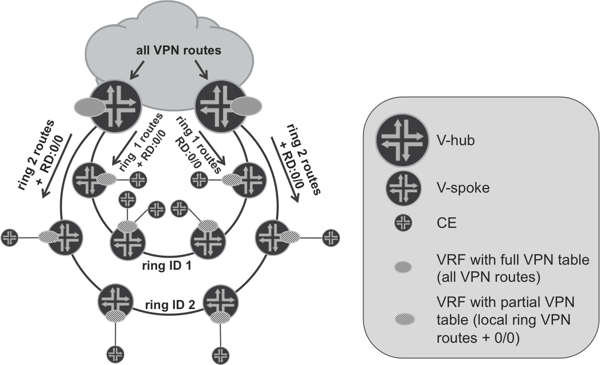
Figure 17-5. Default route with local routes L3VPN model
When communicating between V-spokes on the same ring (access domain), the default route injected by V-hubs is not used. Conversely, when the need arises to communicate between V-spokes in different rings (or with some remote PEs), the default route injected by V-hubs is indeed used. This doesn’t cause any huge inefficiency in traffic forwarding, because to reach remote V-spokes, packets must transit V-hubs anyway.
To achieve the desired results, you can use a community scheme introduced into the base model for Hierarchical VPN. Simply, V-hubs will use the community not only as a condition to announce VPN default route, they will also be used to reflect VPN prefixes received from the local access domain back to V-spokes in the same local access domain. Example 17-43 and Example 17-44 demonstrate simple extensions to existing PL-BGP-VPN-DOWN-EXP policy for ASBR1 (Junos) and ASBR2 (IOS XR), respectively.
Example 17-43. IPv4 VPN outbound BGP policy on ASBR1 (Junos)
policy-options {
    policy-statement PL-BGP-VPN-DOWN-EXP {
        term LOCAL-DEFAULT-ROUTE {
(...)
        }
        term ACCESS-DOMAIN-100 {
            from {
                family inet-vpn;
                community CM-IPV4-VPN-100;
            }
            then accept;
        }
        term VRF-C {
(...)
        }
        from family inet-vpn;
        then accept;
}}
Example 17-44. IPv4 VPN outbound BGP policy on ASBR2 (IOS XR)
route-policy PL-BGP-VPN-DOWN-EXP
  if community matches-any CM-VPN-DEFAULT-ROUTE then
    done
  elseif community matches-any CM-IPV4-VPN-100 then
    done
  elseif extcommunity rt matches-any RT-VPN-C then
    drop
  endif
  pass
end-policy
You can perform similar policy extensions on ABR1 and ABR2. With updated BGP outbound policies on V-hubs, the number of prefixes sent to V-spokes increases slightly (10 additional paths, and out of those, 3 additional active prefixes). You can compare the output in the following examples with that from Example 17-7 and Example 17-8.
Example 17-45. VRF-C prefix state on PE1 (Junos)
juniper@PE1> show route summary
(...)
VRF-C.inet.0: 12 destinations, 15 routes (12 active, ...)
              Direct:      3 routes,      3 active
               Local:      3 routes,      3 active
                 BGP:      14 routes,     5 active
              Static:      1 routes,      1 active
(...)
Example 17-46. VRF-C Prefix State on PE2 (IOS XR)
RP/0/0/CPU0:PE2#show route vrf VRF-C summary
Route Source        Routes     Backup     Deleted   Memory(bytes)
connected           2          1          0         444
local               3          0          0         444
static              1          0          0         148
bgp 65001           4          0          0         592
ospf VRF-C          1          0          0         148
dagr                0          0          0         0
Total               11         1          0         1776
If you look at the VPN-C topology (Figure 17-4), three additional active prefixes are actually expected. For example, on PE1 router, the following three additional active BGP prefixes in VRF-C:
-
Loopback of CE2-C router
-
VRF-C loopback of PE2 router
-
LAN prefix from PE2-CE2-C link
There are two additional prefixes (loopback of CE5-C and prefix for LAN connected to CE5-C) advertised to V-hubs from PE2 and reflected back to PE1. However, because for those prefixes there are already better (local/static) prefixes present in the VRF-C table on PE1, BGP prefixes received from V-hubs are not activated.
So, in summary, you see an additional five prefixes (received twice, because there are two V-hubs sending them), of which three are actually actively used for forwarding. If you compare this with Example 17-1 or Example 17-2, it is still a much lower number than with nonhierarchical L3VPN. A similar result occurs in all other PE routers.
Now, when you check the forwarding path between CE3-C and CE4-C routers, based on additional prefixes distributed to local V-spokes, packets are forwarded on the shortest path, as shown here:
Example 17-47. Optimal traceroute from CE3-C to CE4-C
juniper@CE3> traceroute routing-instance CE3-C source 192.168.3.3
             192.168.3.4
traceroute to 192.168.3.4 (192.168.3.4) from 192.168.3.3, 30 hops max
 1  PE3-VRF-C (10.3.3.1)  14.720 ms  3.269 ms  2.393 ms
 2  PE4 (10.0.21.11)  58.005 ms  67.934 ms  28.708 ms
     MPLS Label=24003 CoS=0 TTL=1 S=1
 3  CE4-C (192.168.3.4)  8.510 ms  9.473 ms  6.866 ms
Pseudowire Head-End Termination L3VPN Model
In previous sections of this chapter, you built a Hierarchical L3VPN service, based on the assumption that V-spokes do support L3VPN, including support for multiprotocol BGP. This is, unfortunately, not always the case. In many designs, you can find V-spokes without BGP support at all. Naturally, with no BGP, there is no L3VPN possible on V-spokes, either.
Therefore, you will need another approach for Hierarchical L3VPN, one which requires only L2 capabilities (including support for MPLS pseudowires to carry L2 traffic) from the V-spoke. The principle is based on a pseudowire (PW) established between V-spoke and V-hubs. Basically, traffic received from a CE is bridged on the V-spoke to the PW terminated on the V-hub. Because you can terminate many PWs from many V-spokes on V-hubs, and from the CE’s perspective the L3 segment also terminates at the V-hub, the model is commonly known as the pseudowire head-end termination (PWHE) model.
Figure 17-6 presents the overall architecture for this Hierarchical L3VPN model.
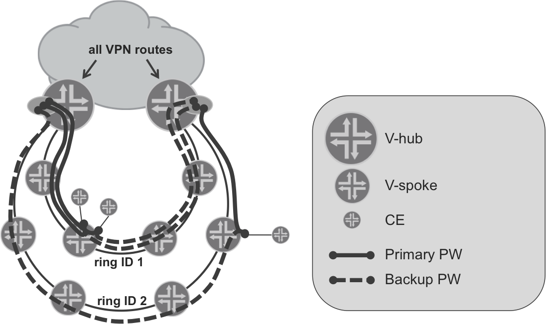
Figure 17-6. The pseudowire head-end termination L3VPN model
Figure 17-6 shows that VRFs are no longer present on the V-spokes—the V-spokes act simply as bridging devices and bridge the traffic between the physical access interface toward the CE, and the PW toward the V-hub. Of course, for redundancy purposes, typically primary/backup PW deployments are recommended, with the primary PW terminated on the primary V-hub, and the backup PW terminated on the backup V-hub. There could be multiple VLANs (corresponding to multiple VPNs) transported inside each PW. At the head-end (V-hub), those VLANs are demultiplexed from the PWs, and each VLAN is placed in appropriate VRF to allow further processing of the packets at L3.
With this architecture, the capability of V-spoke is further “degraded.” Prefix scalability is no longer needed at all, because now the only prefixes the V-spoke must deal with are transport network prefixes. Typically, as already discussed in Chapter 16, a large transport network can be divided into multiple smaller IGP domains; thus, the prefix information inside each IGP domain can be quite minimal. Additionally, the only requirement from a protocol-support perspective is some sort of label distribution protocol, IGP, and support for LDP signaled PWs. Thus, Hierarchical L3VPN based on the PWHE model is the primary choice when quite dummy (and cheap) V-spokes are deployed.
However, although the possibility to deploy V-spokes without comprehensive L3 service support might sound advantageous, there are, of course, some disadvantages. First, traffic optimization achieved by injecting VPN routes that originated in the local IGP domain, as discussed in previous section, is no longer possible. Consequently, traffic between CE devices connected to V-spokes in the same IGP now always traverses through the V-hub. For some applications, for which latency must be minimized, the Hierarchical L3VPN model based on PWHE might consequently be unsuitable.
Another disadvantage is the increased bandwidth usage in access IGP domains. Whereas in the previously discussed Hierarchical L3VPN model, MPLS-encapsulated IP packets were exchanged between V-spokes and V-hubs in the PWHE model, MPLS encapsulated Ethernet frames carrying IP payload are exchanged. Additional overhead is around 14 to 26 bytes per packet, depending on the number of VLAN tags carried, and whether the control word is used. Although this doesn’t look large at the first glance, it might increase bandwidth requirements significantly in some deployments. If the majority of carried traffic uses small IP packets (e.g., VoIP packets using G.729 codec with IP packet sizes as low as 60 bytes) bandwidth usage can increase by 20%–40%. Suboptimal traffic routing (always via V-hub) causes additional bandwidth inefficiency, because traffic exchanged between two V-spokes in the same IGP access domain traverses IGP access domain twice. If your bandwidth resource is limited—for example, limited bandwidth microwave links are used—those disadvantages of the PWHE Hierarchical L3VPN model might be too big to justify deployment of devices without even limited L3VPN support in a V-spoke function. The details are beyond the scope of this book.