During failure of a primary egress PE, preinstallation of the next hop associated with the backup egress PE reduces the failover time from seconds to a few hundred milliseconds. BGP convergence is no longer the contributing factor, because the second BGP next hop is preinstalled in the FIB.
However, IGP convergence still contributes to the overall failover time, because the ingress PE must discover failure of the primary egress PE to remove the associated next hop from the FIB. To reduce the detection time to less than a few hundred milliseconds (IGP convergence), you could deploy next-hop tracking or BGP session liveness detection mechanisms (using, for example, multihop Bidirectional Forwarding Detection [BFD]) with very aggressive timers. Very aggressive timers on multihop BFD sessions are, however, a questionable solution from a deployment (scaling) perspective, especially in large-scale networks, where a large number of such BFD sessions would be required.
So, what can you do? The answer is to move the duty of fixing the problem from the ingress PE (which is potentially far away from egress PE) to the network node closest to the egress PE. If the network node (let’s call it Point of Local Repair [PLR]) directly connects to the egress PE, a failure of the egress PE can be discovered very quickly, without the need for IGP convergence. Upon failure of the primary egress PE, the PLR node redirects the traffic. Therefore, traffic is locally repaired (redirected by the PLR), and the ingress PE has time to detect the primary egress PE failure and make changes in its FIB next-hop structures.
Service Mirroring Protection Concepts
At first sight, the concept of service mirroring protection seems to be easy enough, but there are some challenges that must be solved:
How does the PLR know to which node traffic should be redirected?
The PLR is a typical P node, without any knowledge about VPN prefixes or VPN labels. Thus, based on VPN prefixes or VPN labels, the PLR is not able to correctly determine the proper node to which the traffic should be redirected.
How does the backup egress PE handle traffic originally destined to the primary egress PE?
Even assuming that the traffic is somehow redirected and eventually arrives at the proper backup egress PE, how can such traffic be handled at the backup egress PE? When simply redirecting the traffic, the VPN label of the packets arriving to the backup egress PE is assigned by the primary egress PE. Each label has local significance, so label X assigned by the primary egress PE can have a completely different meaning than label X assigned by the backup egress PE. If the now-redirected packet with label X arrives at the backup egress PE, it might be dropped (the backup egress PE didn’t allocated label X at all), or it might be forwarded to wrong destination.
To solve the first problem, both the primary egress PE and node where the traffic is redirected to advertise a shared anycast IP address. This is conceptually similar to anycast rendezvous points in multicast deployments, where the same IP address is injected into IGP by multiple routers acting as rendezvous points. When PLR detects the failure of the primary egress PE, using simple local-repair techniques (LFA or RSVP-TE facility backup), traffic can be redirected because the IP address is the same.
To solve the second problem, the primary egress PE and backup egress PE must send (via a direct BGP session or using a BGP Route Reflector [RR]) their VPN bindings (prefix plus label) to the node where the traffic is redirected to by the PLR. This node protects the primary egress PE by translating VPN labels allocated by the primary egress PE to the corresponding VPN labels allocated by the backup egress PE; therefore, this node is called the protector in the overall concept. Because the protector node can protect multiple primary egress PEs, the RIB/FIB structures required for VPN label translation are created separately for each protected primary egress PE. They are built in the context of the anycast IP address mentioned previously; consequently, this IP address is called context ID.
The entire concept is often called service mirroring because the primary egress PE mirrors its VPN information to the protector node. It introduces the following network functions and uses the following terminology:
Ingress PE node
The ingress PE node receives the traffic from the locally connected VPN site, encapsulates the traffic by using the VRF–specific MPLS label stack, and sends it to the egress PE using context-ID anycast IP address.
Primary egress PE node
The primary egress PE is a node that normally receives VPN traffic flows destined to a multihomed (connected to primary and backup egress PE) VPN site. If the ingress PE performs load-balancing toward multiple egress PEs (this is the Active/Active next hops to egress PEs model discussed in Chapter 20), it means some of the flows are sent toward one egress PE, whereas the other flows are sent toward the second egress PE. From the egress protection (service mirroring) architecture perspective, the definition of primary egress PE is bound to actual traffic flow.
Backup egress PE node
The backup egress PE is a node that normally does not receive VPN traffic flows destined to a multihomed (connected to primary and backup egress PE) VPN site. Again, in the case of load-balancing performed by the ingress PE, the definition of backup egress PE is bound to actual flow. Assuming perfect load-balancing, for 50% of the flows, the first egress PE is the primary egress, whereas the second egress PE is the backup egress. For the remaining 50% of flows, it is just the opposite: the second egress PE is the primary egress, whereas the first egress PE is the backup egress.
PLR node
This is the node directly connected to the primary egress PE. Upon failure detection of the primary egress PE (or link toward the primary egress PE), the PLR redirects the traffic toward the protector node. Redirection uses local-repair techniques (LFA or RSVP-TE facility protection), thus failover is very fast (~50 ms).
Protector node
This is the node accepting traffic redirected by the PLR and performing the VPN label translation on received VPN packets. It translates the VPN label allocated by the primary egress PE to the VPN label allocated by the backup egress PE, and then sends the packet with translated VPN label to the backup egress PE. Therefore, the protector must receive appropriate BGP VPN updates from the primary and backup egress PE nodes.
Context-ID
This is the anycast IP address advertised by the primary egress PE and the protector node. Characteristics (e.g., IGP metric) of the anycast IP address advertised by the primary egress PE are better than those advertised by the protector node. Thus, normally the traffic is routed through the network toward the primary egress PE. The primary egress PE uses this anycast IP address as the BGP protocol next hop in outbound BGP updates for NLRIs requiring egress protection. The protector advertises the same anycast IP address in order to attract the traffic in case of primary egress PE failure.
This concept is described in draft-minto-2547-egress-node-fast-protection and illustrated in Figure 21-1.
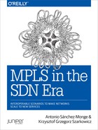
Figure 21-1. Egress protection (service mirroring) topology—combined protector/backup egress PE model
You can deploy egress protection (service mirroring) by using two major architectural models:
Combined protector/backup egress PE model
In the combined model, the protector function and the backup egress PE functions are combined on a single node. Thus, in this model no real translation of VPN labels is required, because the traffic redirected by the PLR to the combined protector/backup egress PE node can be immediately sent to the directly attached multihomed VPN site. However, forwarding of redirected traffic must be based on the VPN labels allocated by the primary egress PE.
Separate (centralized) protector and backup egress PE model
In the centralized protector model, the function of the backup egress PE and the protector are implemented on physically separate nodes. Such a deployment model creates the opportunity to implement egress protection (service mirroring) architecture without any specific support required on the PE nodes. VPN label translation, demanding some sort of support in hardware, is implemented exclusively on the dedicated protector node (or nodes). PEs are standard PEs without any knowledge about egress protection (service mirroring); they simply receive VPN packets with their own VPN labels.
Figure 21-1 shows the combined protector/backup egress PE model only (the centralized protector model is discussed later in this chapter). Traffic flows from right (CE3, CE4, CE6) to left (CE5), flowing normally through the primary egress PE (PE2), are protected by PE1 acting as a combined protector/backup egress PE.
Note
As of this writing, IOS XR does not support the protector function in the overall service mirroring architecture. All other node types used in service mirroring architecture (ingress PE, primary egress PE, backup egress PE, PLR) are supported on IOS XR.
Combined Protector/Backup Egress PE Model
Let’s begin this model discussion with the combined protector/backup egress PE model. In this model, PE3 and PE4 are ingress PEs, PE2 (IOS XR) is deployed as the primary egress PE, whereas PE1 is used as the combined protector/backup egress PE. On PE2 (primary egress PE), the following modifications are required:
BGP VPN NLRI updates advertised by PE2 have MED=0 (lower than on PE1) to ensure that PE2 is the primary egress PE.
The BGP protocol next hop for these updates is changed by the outbound policy to the secondary address (172.17.0.22) of the loopback interface. This IP address is the context-ID anycast address as mentioned previously.
The secondary address of the loopback interface is injected into IS-IS (with metric 0) and LDP (with implicit null label).
Example 21-1 summarizes these small configuration changes required on PE2.
Example 21-1. Primary egress PE configuration on PE2 (IOS XR)
Now, PE1 must act as the combined protector/backup egress PE. This results in the following:
BGP VPN NLRI updates advertised by PE1 have MED=1000 (higher than on PE2), to ensure that the PE1 is backup egress PE
The BGP protocol next hop remains the default (primary address of loopback interface)
The protector context-ID (172.17.0.22—the same IP address as used on the primary egress PE) must be defined and injected into IS-IS with high metric (default is 224-2=16777214) and into LDP (with real, and not implicit null label).
The BGP sessions toward the RRs are enabled to support egress-protection for the IPv4-VPN address family.
Again, here are the changes required on the combined protector/backup egress PE.
Example 21-2. Combined protector/backup egress PE configuration at PE1 (Junos)
protocols {
    mpls {
        egress-protection {
            context-identifier 172.17.0.22 protector;
        }
    }
    bgp {
        group IBGP-RR {
            family inet-vpn unicast {
                egress-protection;
}}}}
policy-options {
    policy-statement PL-VRF-B-EXP {  ## policy for other VRFs similar
        then {
            metric 1000;             ## higher than on PE2
            origin incomplete;       ## the same as on PE2
            community add RT-VPN-B;
            accept;
}}}
routing-instances {
    VRF-B {
        vrf-export PL-VRF-B-EXP;     ## other VRFs similar
}}
Note
The context-ID IP address (172.17.0.22/32) is now originated by PE1 and PE2. Thus, on Junos PLR routers (P1 and P2), LFA must be prepared to handle protection of the prefixes originated by multiple routers. You must enable the per-prefix-calculation, as described in Chapter 18.
After implementing the configuration changes, let’s verify the states in the network.
Example 21-3. IS-IS and LDP states for PE2 context-ID
Verification confirms that the primary egress PE (PE2) advertises the context-ID IP address with a low IGP metric (line 7) and an implicit null label (line 11). The protector (PE1), on the other hand, advertises the same context-ID IP address with a high IGP metric (line 4) and a real label (line 17). Apart from configuring the protector context-ID on PE1, no special configuration is required to achieve this behavior.
The requirements for different IGP metrics are easy to understand: the ingress PEs (PE3 and PE4) should prefer PE2 to reach 172.17.0.22, because in our design PE2 is the primary egress PE. But why does the protector (PE1) advertise a real LDP label, instead of advertising an implicit null, as the primary egress PE (PE2) does?
Let’s try to verify routing states on the path from an ingress PE, (e.g., PE3) to reach the loopback of CE5-B (see Example 21-4).
Example 21-4. RIB/FIB states on the path from PE3 (ingress PE) to PE1 (protector)
The FIB state observed on PE3 is standard, as already discussed in Chapter 18 and Chapter 20. PE3 sends packets with a label stack (16108, 300800) via P1 (the primary next hop to reach 172.17.0.22 used as a BGP next hop) or with a label stack (16108, 300112) via PE4 (the backup LFA next hop to reach 172.17.0.22). When the packet arrives at P1, the top label is removed and the packet is sent via direct link to PE2 (the primary next hop to reach 172.17.0.22), or the top label is swapped and the packet is sent via direct link to PE1 (the backup LFA next hop to reach 172.17.0.22). Thus, when PE2 (the primary PE) fails, P1 redirects the traffic to PE1 (the protector/backup PE) very quickly—based on local repair.
Now, as mentioned earlier, when redirected packets arrive to PE1 (the protector/backup egress PE), they need to be forwarded to the local CE devices based on VPN labels allocated by PE2 (the primary egress PE). P1, which performs redirection, does not alter the VPN label in any way, so the PE2 allocated VPN label is still in the MPLS header of packets redirected to PE1. To achieve that, PE1 needs to do the following:
Realize that packets arriving from the MPLS core require special treatment, because they are not normal VPN packets, but packets originally destined to PE2 which are just redirected by P1 to PE1.
Use VPN labels allocated by another PE (PE2) for traffic forwarding.
To achieve the desired functionality, the protector/backup egress PE creates multilevel, multifamily (MPLS and IP) RIB structures, as illustrated in Figure 21-2 as well as the subsequent outputs from several Junos operational commands shown in Example 21-5.
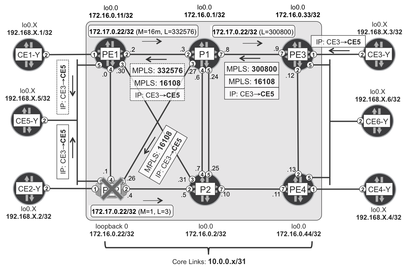
Figure 21-2. RIB structures on combined protector/backup egress PE node—PE1 (Junos)
Example 21-5. RIB structures on combined protector/backup egress PE node—PE1 (Junos)
1     juniper@PE1> show route table mpls.0 label 332576
2     (...)
3     332576(S=0)        *[LDP/0] 00:07:58
4                           to table __172.17.0.22__.mpls.0
5
6     juniper@PE1> show route table __172.17.0.22__.mpls.0
7     (...)
8     16106              *[Egress-Protection/170] 19:42:05
9                           to table __172.17.0.22-VRF-B__.inet.0
10    16107              *[Egress-Protection/170] 19:42:05
11                          to table __172.17.0.22-VRF-B__.inet.0
12    16108              *[Egress-Protection/170] 19:42:05
13                          to table __172.17.0.22-VRF-B__.inet.0
14    16109              *[Egress-Protection/170] 19:42:05
15                          to table __172.17.0.22-VRF-C__.inet.0
16    16110              *[Egress-Protection/170] 19:42:05
17                          to table __172.17.0.22-VRF-C__.inet.0
18    16111              *[Egress-Protection/170] 19:42:05
19                          to table __172.17.0.22-VRF-C__.inet.0
20
21    juniper@PE1> show route table __172.17.0.22-VRF-B__.inet.0
22    (...)
23    10.2.5.0/24        *[Egress-Protection/170] 19:43:09
24                          to table VRF-B.inet.0
25    192.168.2.5/32     *[Egress-Protection/170] 19:43:09
26                        > to 10.2.5.5 via ge-2/0/5.2
27
28    juniper@PE1> show route table __172.17.0.22-VRF-C__.inet.0
29    (...)
30    10.3.5.0/24        *[Egress-Protection/170] 19:43:15
31                          to table VRF-C.inet.0
32    192.168.3.5/32     *[Egress-Protection/170] 19:43:15
33                        > to 10.3.5.5 via ge-2/0/5.3
First, you can see that the label allocated to the protector context-ID is a real label (lines 1 through 4 in Example 21-5, and line 17 from Example 21-3). A real label (and not an implicit null label) is required. Otherwise, PE1 is not able to determine that the arriving packet requires some special treatment. Therefore, for every configured protector context-ID, the protector generates a separate (real) label. In this example, PE1 is configured with the single protector context-ID, but in more complex scenarios, you can configure multiple protector context-IDs. There are some examples of those later in the chapter.
The (real) protector context-ID label is installed in mpls.0 table and points to an auxiliary table called __172.17.0.22__.mpls.0. Therefore, when packets with the label 332576 arrive at PE1, PE1 removes (pops) the label and performs a next lookup in this auxiliary table. But what is this table? This table collects all VPN labels allocated by the primary PE. Accordingly, this auxiliary table is called the context label table. If you compare lines 6 through 19 in Example 21-5 with those from Example 21-6, you will see the similarities.
Example 21-6. VPN labels of VRF-B and VRF-C routes received from PE2
And that is the reason why the protector node allocates real (not implicit null) labels when advertising protector context-IDs in LDP. Based on this real label, the protector is able to determine that the packet needs special treatment, and performs a second lookup in the context label table, where labels from the primary egress PE are collected. How is this table built? It is based on received BGP NLRIs with the BGP protocol next hop equal to the configured protector context-ID. Because the example’s primary egress PE (PE2) uses 172.17.0.22 as a next hop (Example 21-1), the protector (PE1) collects VPN labels of received VPN prefixes with the next hop 172.17.0.22 (protector context-ID) and uses these VPN labels to build a context label table for 172.17.0.22 context-ID.
Entries in the context label table (__172.17.0.22__.mpls.0) point to (multiple) context-ID/VRF specific IP auxiliary tables: __172.17.0.22-VRF-B__.inet.0 and __172.17.0.22-VRF-C__.inet.0. These auxiliary tables are still built based on IP VPN prefixes received from the primary egress PE. However, as opposed to the case with the context label table, the backup egress PE only installs the prefix in the IP auxiliary table if there is a match between the IP VPN prefix received from the primary egress PE, and the prefix in the local VRF. In this particular case, for example, PE1 installs only two prefixes in each IP auxiliary table (lines 21 through 33 in Example 21-5). What are these two prefixes? They are the loopback of the dual-homed CE5-B (or CE5-C) and the shared LAN prefix for PE1-PE2 connectivity inside VRF-B and VRF-C. Other prefixes advertised by PE2 (e.g., the loopback of CE2-B: 192.168.2.2/32) are not used by PE1 to populate the IP auxiliary tables. Put simply, they cannot be used to protect traffic destined to such prefixes, because PE1 is not connected to the CEs advertising these prefixes. In other words, there is no multihomed CE advertising 192.168.2.2/32 and connected to both the primary egress PE (PE2) and the protector/backup egress PE (PE1).
If you carefully examine the content of the IP auxiliary tables, you should realize that for some prefixes (the loopbacks of directly connected dual-homed CEs) the entry points directly to the outgoing interface. So, this is the final lookup. For some other prefixes (shared LAN prefixes connecting PE1, PE2, and dual-homed CE), the entry points to the next table, which this time is the VRF table presented normally on the (backup) egress PE. Why this difference? If the final destination, including L2 encapsulation (destination MAC address) can be unambiguously determined from the prefix, the IP auxiliary table contains all this information, so no further lookup is needed. If, however, it is not the case (e.g., on 10.2.5.0/24 subnet there could potentially be 254 hosts, each host with a different MAC address, so it is not possible to associate the single destination MAC with the 10.2.5.0/24 prefix), the packet is handed over (next lookup) to normal VRF for further processing. In normal VRF, all features required for packet forwarding are available; for example, ARP machinery for LAN segments to determine the MAC address.
Note
The protector function in service mirroring architectures require multilevel (up to four levels), multiprotocol (MPLS and IP), lookup implementation in the hardware FIB (HW FIB). This functionality is natively available in Junos in those hardware platforms based on the Trio architecture (all types of MPC line cards for MX Series router). In other Junos platforms, a virtual tunnel (VT) interface implemented in the Packet Forwarding Engine (PFE) is required on routers acting as the protector node.
You are almost done with your first egress protection (service mirroring) design. There is, however, one issue that requires more attention. If you go back to the configuration of the primary egress PE (Example 21-1), you’ll see that for all VPN prefixes the next hop is changed to 172.17.0.22. Is this a correct design? What happens to traffic destined to single-homed CEs (e.g., CE2-B) during network failure events?
For the purpose of the discussion, let’s temporarily disable the PE2-P1 and PE2-P2 links so that PE2 is reachable only via PE1. Therefore, all traffic from the MPLS core destined for PE2 must flow over PE1. Now let’s check how you can reach the loopback of CE2-B from PE3.
Example 21-7. RIB states on the path from PE3 (ingress PE) to PE1 (protector)
1     juniper@PE3> show route 192.168.2.2/32 table VRF-B active-path
2     (...)
3     192.168.2.2/32
4          *[BGP/170] 02:18:52, MED 101, localpref 100, from 172.16.0.201
5             AS path: ?, validation-state: unverified
6           > to 10.0.0.8 via ge-2/0/7.0, Push 16107, Push 300800(top)
7             to 10.0.0.13 via ge-2/0/2.0, Push 16107, Push 300112(top)
8
9     juniper@P1> show route label 300800
10    (...)
11    300800 (S=0)       *[LDP/9] 00:00:32, metric 21
12                        > to 10.0.0.2 via ge-2/0/2.0, Swap 332576
13
PE3 attaches a standard label stack with two labels: VPN label 16107 (allocated by primary PE—PE2) and transport LDP label 300800. Subsequently, PE3 sends the packet toward P1. This time on P1, however, there is only one outgoing interface pointing toward PE1, because due to the previously disabled links, PE2 is reachable only via PE1. P1 uses the same label (332576), as discussed previously, when forwarding the traffic toward PE1.
And what happens now to the traffic, when traffic arrives at PE1? If you go back to the previous discussion (lines 1 through 4 in Example 21-5), you will realize that the traffic is intercepted by PE1. It is not forwarded to PE2. What does that mean?It means that the traffic is blackholed. Why? As discussed previously, PE1 installs label 16107 (used by PE2 for the loopback of CE2-B) in its context label table (lines 10 and 11 in Example 21-5). But PE1 does not install the loopback of CE2-B in its auxiliary IP table (lines 21 through 26 in Example 21-5). It basically means, the third lookup does not provide any results, and thus traffic is blackholed.
How can you prepare the design to defend the network against such failure scenarios? You change the next hop to context-ID (secondary loopback address) with caution, and only for prefixes advertised by multihomed CEs connected to both primary and protector/egress PE nodes. All other prefixes should use the standard next hop (the primary loopback address). In such a way, if traffic associated with the standard next hop flows through the protector node, the protector node will not intercept it. The protector node will simply forward the traffic toward the primary egress PE.
So, let’s slightly modify the configuration (Example 21-1) on the primary egress PE to that shown in Example 21-8.
Example 21-8. Route-policies to support service mirroring on PE2 (IOS XR)
1     vrf VRF-B
2      address-family ipv4 unicast
3       export route-policy PL-VRF-B-EXP        ## other VRFs similar
4     !
5     community-set CM-MULTI-HOMED
6       65000:41201
7     end-set
8     !
9     route-policy PL-VRF-B-EXP           ## policy for other VRFs similar
10      if destination in (192.168.2.5/32, 10.2.5.0/24) then
11        set community CM-MULTI-HOMED
12      endif
13      done
14    end-policy
15    !
16    route-policy PL-BGP-UP-VPN-EXP
17      if community matches-any CM-MULTI-HOMED then
18        set next-hop 172.17.0.22
19        delete community in CM-MULTI-HOMED
20        done
21      endif
22      done
23    end-policy
The configuration basically marks multihomed prefixes with a community (lines 5 through 7) using an extra VRF export policy (lines 9 through 14) in an affected VRF (line 3). Then, it modifies the BGP export policy already defined in Example 21-1 to ensure that only multihomed prefixes have their next hop changed to the secondary loopback address (lines 17 through 21). All other VPN prefixes are advertised without next hop modification (line 22), which results in the primary loopback address being used as the BGP next hop.
With this small modification, the protector node, as verified by the outputs presented in Example 21-9, no longer intercepts traffic destined to single-homed prefixes.
Example 21-9. RIB states on the path from PE3 (ingress PE) to PE2
1     juniper@PE3> show route 192.168.2.2/32 table VRF-B active-path
2     (...)
3     192.168.2.2/32
4          *[BGP/170] 00:23:17, MED 101, localpref 100, from 172.16.0.201
5             AS path: ?, validation-state: unverified
6           > to 10.0.0.8 via ge-2/0/7.0, Push 16107, Push 300880(top)
7             to 10.0.0.13 via ge-2/0/2.0, Push 16107, Push 300144(top)
8
9     juniper@PE3> show route 192.168.2.5/32 table VRF-B active-path
10    (...)
11    192.168.2.5/32
12         *[BGP/170] 00:23:42, MED 0, localpref 100, from 172.16.0.201
13            AS path: ?, validation-state: unverified
14          > to 10.0.0.8 via ge-2/0/7.0, Push 16108, Push 300800(top)
15            to 10.0.0.13 via ge-2/0/2.0, Push 16108, Push 300112(top)
16
17    juniper@P1> show route label 300880
18    (...)
19    300880(S=0)        *[LDP/9] 07:30:39, metric 20
20                        > to 10.0.0.2 via ge-2/0/2.0, Swap 332752
21
22    juniper@PE1> show route label 332752
23    (...)
24    332752(S=0)        *[LDP/9] 07:30:49, metric 10
25                        > to 10.0.0.1 via ge-2/0/4.0, Pop
PE3 uses a different LDP transport label to reach the single-homed prefix (loopback of CE2-B) and the multihomed prefix (loopback of CE5-B): 300880 (line 6) versus 300800 (line 14). This should be obvious, because the BGP protocol next hop advertised for these prefixes by PE2 is now different: 172.16.0.22 versus 172.17.0.22. Lines 17 through 25 confirm that P1 and PE1 simply forward the traffic to PE2 by performing standard label operations: swap (P1, line 20) and pop (PE1, line 25). Therefore packets arrive at PE2 with a single VPN label and can be forwarded without any problems to the single-homed CE.
Separate (Centralized) Protector and Backup Egress PE Model
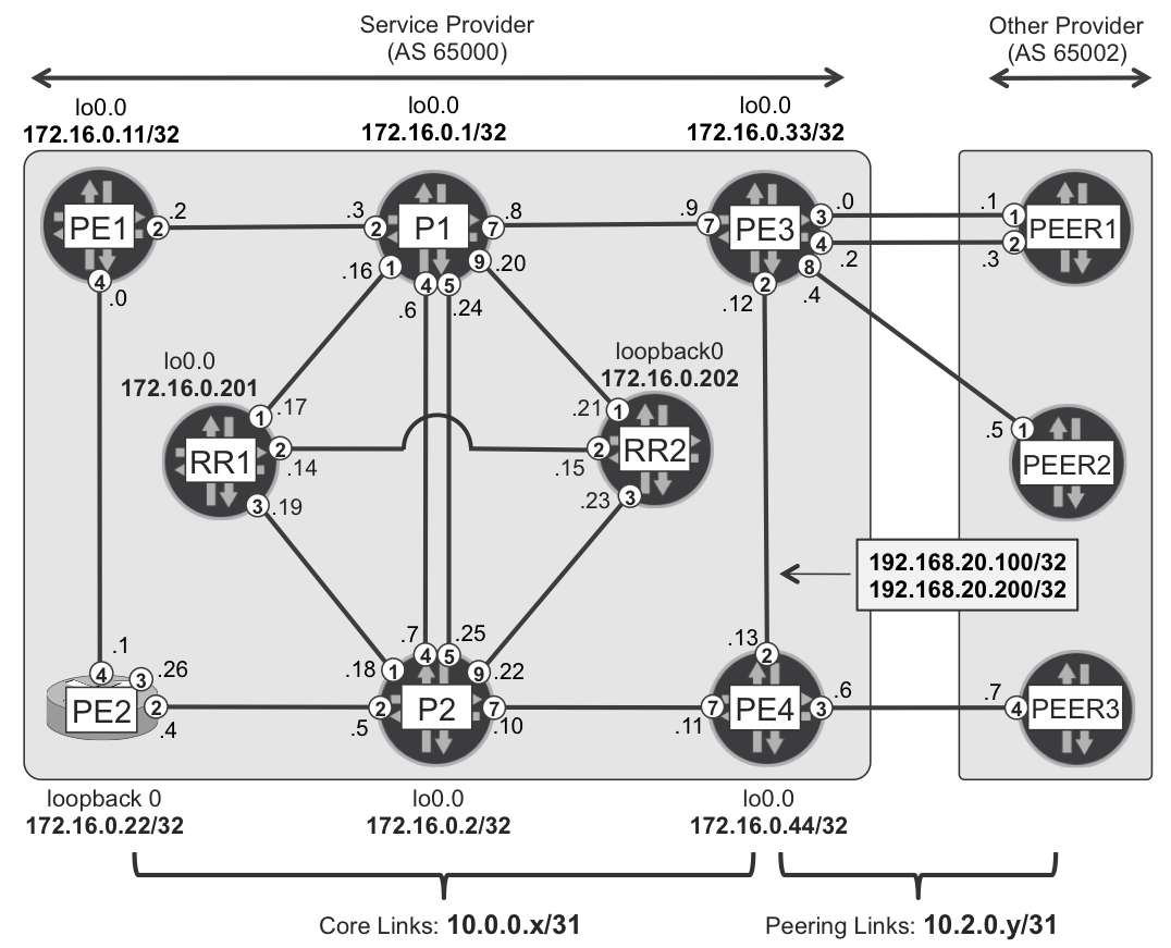
The previous section discussed, in detail, the egress protection (service mirroring) model, wherein the protector function and the backup egress PE function was implemented on the same node (PE1). This is not always the case, so let’s quickly discuss a deployment model in which these two functions are implemented on different physical nodes, as shown in Figure 21-3.
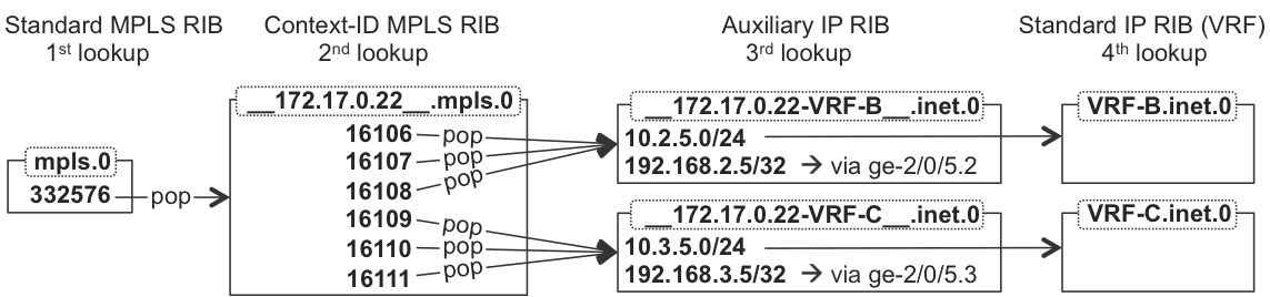
Figure 21-3. Egress protection (service mirroring) topology—centralized protector model
In this scenario, flows from the left side (CE1, CE2, and CE5) to the right side (CE6) are protected by a separate protector node: PR. Both ingress PEs (PE1 and PE2) perform load-balancing (Active/Active next hops to egress PEs) toward both egress PEs (PE3 and PE4). Therefore, for approximately half of the CE6-bound flows, PE3 is the primary egress PE, whereas PE4 is the backup egress PE. For the remaining half of the flows, it’s just the opposite: PE3 is the backup egress PE, whereas PE4 is the primary egress PE. Figure 21-3 shows an example flow from PE2 to PE4 only. Both egress PEs inject their context-IDs (172.17.0.33 and 172.17.0.44, respectively) with a low (equal to 1) IGP metric and with an LDP implicit null label. The PR node is now a separate protector node performing translation of VPN labels from the primary egress PE to VPN labels allocated by the backup egress PE.
Let’s begin with the configuration adjustments on the PE routers (Example 21-10).
Example 21-10. Primary egress PE configuration on PE3 (Junos)
1     protocols {
2         mpls {
3             egress-protection {
4                 context-identifier 172.17.0.33 primary;
5             }
6         }
7         bgp {
8             group IBGP-RR {
9                 family inet-vpn {
10                    unicast {
11                        egress-protection;
12                    }
13                }
14                export PL-BGP-SET-CONTEXT-ID;
15                vpn-apply-export;
16    }}}
17    policy-options {
18        policy-statement PL-BGP-SET-CONTEXT-ID {
19            term MULTI-HOMED {
20                from tag2 41201;
21                then {
22                    next-hop 172.17.0.33;
23                    accept;
24                }
25            }
26        }
27        policy-statement PL-VRF-B-EXP { ## similar policy for other VRFs
28            term MULTI-HOMED {
29                from interface ge-2/0/5.2;
30                then tag2 41201;
31            }
32            then {
33                community add RT-VPN-B;
34                accept;
35            }
36        }
37        community RT-VPN-B members target:65000:1002;
38    }
39    routing-instances {
40        VRF-B {
41            vrf-export PL-VRF-B-EXP;    ## other VRFs similar
42    }}
First, the context-ID must be specified. One option is to specify the primary context-ID in the protocols mpls section (lines 2 through 6). With this option, the specified context-ID is automatically advertised via IGP and LDP. Another viable option is to specify the primary context-ID as the secondary loopback address—in a similar way as was presented in Example 21-1 for IOS XR.
Next, you must enable egress protection functionality in BGP (line 11). At this configuration level, you can also specify the context-ID address (set protocols bgp group IBGP-RR family inet-vpn unicast egress-protection context-identifier 172.17.0.33). However, this is not advisable, if you have single-homed and multihomed CEs connected to the PE. This command results in the BGP protocol next hop being automatically changed to the context-ID for all VPN prefixes. As discussed previously, changing the BGP protocol next hop for single-homed prefixes might lead to traffic blackholing in certain situations.
Thus, you will manipulate the next hop only for multihomed prefixes. One option is to use a special community, in a similar way as discussed in Example 21-8. Another option is to use the interim tag2 parameter instead of the community. In this way, you don’t need to remove the community (like in Example 21-8, line 19), because tag2 has local significance only—it is not advertised to routing peers. So, you select multihomed prefixes—the simplest way is to use the interface as selection criteria (line 29) in the VRF export policy. All prefixes reachable via the interface connected to the multihomed CE will be marked with some tag2 value (line 30). You don’t need to know exactly what the prefixes are, just the interface. Next, on the BGP export policy (line 14), you change next hop to context-ID for tagged prefixes only (lines 22), while keeping the default next hop for other prefixes. The vpn-apply-export parameter (line 15), discussed in Chapter 3, is required to ensure that the BGP export policy affects VPN prefixes, as well.
The protector node PR configuration requires special attention. There are no local VRFs on the PR (PR is not backup egress PE). Therefore, you need to specify a route policy that will be the basis for egress protection (service mirroring) RIB/FIB structures. The PR builds the RIB/FIB translation table only for VPN prefixes matching the route policy. For scaling, you could, for example, designate the PR as the protector for VPN-B and VPN-C (as in the configuration shown in Example 21-11), while designating some other router as the protector for other VPNs.
Example 21-11. Separate (centralized) protector configuration on PR (Junos)
1     protocols {
2         mpls {
3             egress-protection {
4                 context-identifier 172.17.0.33 {
5                     protector;
6                 }
7                 context-identifier 172.17.0.44 {
8                     protector;
9                 }
10            }
11        }
12        bgp {
13            group IBGP-RR {         ## group towards route reflectors
14                family inet-vpn {
15                    unicast {
16                        egress-protection {
17                            keep-import PL-BGP-EGRESS-PROTECTION-RT;
18    }}}}}}
19    policy-options {           ## protection for VPN-B and VPN-C only
20        policy-statement PL-BGP-EGRESS-PROTECTION-RT {
21            from community [ RT-VPN-B RT-VPN-C ];
22            then accept;
23        }
24        community RT-VPN-B members target:65000:1002;
25        community RT-VPN-C members target:65000:1003;
26    }
One additional important problem is the configuration of the BGP RR. Or, in general, the configuration of BGP peers sending VPN prefixes to the protector node, if the route reflector design is not used. If constrained route distribution (RFC 4364) is in place (as is discussed in Chapter 3), BGP peers will not send anything to the protector node. Why? Because on pure protector nodes, VRFs are not configured. Therefore the protector node does not advertise toward BGP peers any Route Targets (RTs) inside the RT address family. Thus, based on the constrained route distribution operational model, these BGP peers (RRs) do not advertise any VPN routes to the protector node.
If, on the other hand, the route-target address family is not configured between the protector node and the BGP peers (RRs), these BGP peers send the full VPN table. Whereas the first case prevents proper operation of the protector node (no VPN prefixes received), the second case is not optimal, either. Therefore, let’s configure static RT constraints on the RRs (protector’s BGP peers) in order to send to the protector only those VPN prefixes with specific RTs—as required by the protector.
Example 21-12. Static RT constraint configuration on RR (Junos)
OK, the configuration is complete; let’s verify network operation (see Example 21-13).
Example 21-13. RIB/FIB states on egress and ingress PE, and PLR
1     juniper@PE3> show route advertising-protocol bgp 172.16.0.201 table V
2
3     VRF-B.inet.0: 18 destinations, 38 routes (18 active, 0 holddown)
4       Prefix              Nexthop          MED     Lclpref    AS path
5     * 10.2.3.0/31         Self                     100        I
6     * 10.2.6.0/24         172.17.0.33              100        I
7     * 192.168.2.3/32      Self             100     100        I
8     * 192.168.2.6/32      172.17.0.33      0       100        65506 ?
9     * 192.168.2.33/32     Self                     100        I
10
11    VRF-C.inet.0: 18 destinations, 40 routes (18 active, 0 holddown)
12      Prefix              Nexthop          MED     Lclpref    AS path
13    * 10.3.3.0/31         Self                     100        I
14    * 10.3.6.0/24         172.17.0.33              100        I
15    * 192.168.3.3/32      Self             100     100        I
16    * 192.168.3.6/32      172.17.0.33      0       100        65506 ?
17    * 192.168.3.33/32     Self                     100        I
18
19    RP/0/RSP0/CPU0:PE2#show cef vrf VRF-B 192.168.2.3/32 | include ...
20       via 172.16.0.33, 4 dependencies, recursive [flags 0x6000]
21         next hop 10.0.0.27/32 Gi/0/0/0/3 labels imposed {301040 37}
22
23    RP/0/RSP0/CPU0:PE2#show cef vrf VRF-B 192.168.2.6/32 | include ...
24       via 172.17.0.33, 3 dependencies, recursive, bgp-multipath (...)
25         next hop 10.0.0.27/32 Gi/0/0/0/3 labels imposed {300624 37}
26       via 172.17.0.44, 3 dependencies, recursive, bgp-multipath (...)
27         next hop 10.0.0.5/32 Gi/0/0/0/2 labels imposed {300288 47}
28
29    juniper@P1> show route label 301040 detail | find ... | match ...
30    301040(S=0) (1 entry, 1 announced)
31                Next hop: 10.0.0.9 via ge-2/0/7.0 weight 0x1, selected
32                Label operation: Pop
33
34    juniper@P1> show route label 300624 detail | find ... | match ...
35    300624(S=0) (1 entry, 1 announced)
36                Next hop: 10.0.0.9 via ge-2/0/7.0 weight 0x1, selected
37                Label operation: Pop
38                Next hop: 10.0.0.37 via ge-2/0/8.0 weight 0xf000
39                Label operation: Swap 299808
40
41    juniper@P2> show route label 300288 detail | find ... | match ...
42    300288(S=0) (1 entry, 1 announced)
43                Next hop: 10.0.0.11 via ge-2/0/7.0 weight 0x1, selected
44                Label operation: Pop
45                Next hop: 10.0.0.39 via ge-2/0/8.0 weight 0xf000
46                Label operation: Swap 299824
You can see that the egress PE routers (e.g., PE3) advertise multihomed prefixes with the BGP protocol next hop set to the context-ID (172.17.0.33, in the case of PE3), while using standard next hop (self, which is the address where the BGP session terminates: the primary loopback address) for all other prefixes (lines 1 through 17). On the ingress PE (e.g., PE2) the FIB entry confirms that a different BGP protocol next hop is used (line 20 versus lines 24 and 26), and consequently, a different transport label is used, too (line 21 versus lines 25 and 27). For multihomed prefixes, PE2 load-balances the traffic, because PE2 deploys Active/Active next hops to egress PEs.
On the PLR router (e.g., P1) you can see that the label associated with the primary loopback address of PE3 (lines 20 and 21) is not protected by the LFA backup (lines 29 through 32). Given the network topology (Figure 21-3), this is obvious: there is no loop-free backup path to reach PE3 from P1. You could eventually deploy some more advanced LFA techniques (Remote LFA [RLFA], Topology-Independent Fast ReRoute [TI-FRR]), as discussed in Chapter 18, to enhance backup coverage here.
What is important from this chapter’s perspective, however, is the forwarding state for the label associated with the context-ID of PE3. Lines 38 and 39 show that in the case of PE3 failure, P1 will redirect the traffic to the protector node PR performing label swap operation. You can spot similar behavior on P2, with regard to the failure of PE4 (lines 45 and 46).
You can perform similar investigations for other prefixes (e.g., prefixes from VRF-C) as well as from the perspective of another ingress PE (PE1). In all cases, upon failure detection of the directly connected egress PE router, PLR routers (P1 and P2) redirect the traffic destined to the context-ID of PE3 or PE4 toward the PR node based on the preinstalled LFA backup next hop.
And now, it is the task of the PR router to perform VPN label translation and send the traffic to another (not failed) egress PE—the backup egress PE router in service mirroring architecture. So, let’s check how it is performed now (see Example 21-14). First, verify if the PR receives the proper NLRIs from the RR. As you remember, you are designing the network to protect traffic only for VRF-B and VRF-C, so you made a configuration (Example 21-12) to ensure that the RR only sends VPN prefixes for these two VPNs to the PR.
Example 21-14. VPN prefix propagation between RR and PR
Except where stated otherwise, all of the line numbers in the following two paragraphs refer to Example 21-14. It seems the static RT constraint configuration (Example 21-12) is effective, because the RR installs the appropriate entry in bgp.rtarget.0 RIB (lines 3 through 7). This basically means the RR will send to 172.16.0.10 (PR’s loopback) NLRIs that have a route target from the 65000:65000:1002/95 range. This range covers only two RTs—65000:65000:1002 and 65000:65000:1003—which perfectly covers the RTs used for VRF-B and VRF-C. Furthermore, you can see the RR has 55 active routes in bgp.l3vpn.0 RIB (line 11), but only 40 routes are advertised to the PR node (line 16). Additional checks confirm that 20 of those prefixes have the RT for VRF-B (lines 20 through 22) and 20 have the RT for VRF-C (lines 24 through 26). Given the network topology, this is expected because each PE advertises five prefixes in each VPN: three loopbacks (single-homed CE, multihomed CE, and VRF on PE) and two PE-CE links (single-homed CE and multihomed CE).
Therefore, we can conclude that the RR sends only NLRIs associated with VRF-B and VRF-C to the PR. And, because the PR configuration allows reception of NLRIs with these RTs (Example 21-11, lines 17 through 26), you can see the bgp.l3vpn.0 RIB being populated (lines 28 through 31): 40 routes from each RR. So far, so good—the PR has all information required to build VPN translation tables. To enhance scale, you could further restrict the information advertised to the PR. The only information the PR requires are NLRIs from multihomed CEs in VPN-B and VPN-C connected to two egress PEs (PE3 and PE4). Information from single-homed CEs is not required on PR. This optimization, though, is not configured here.
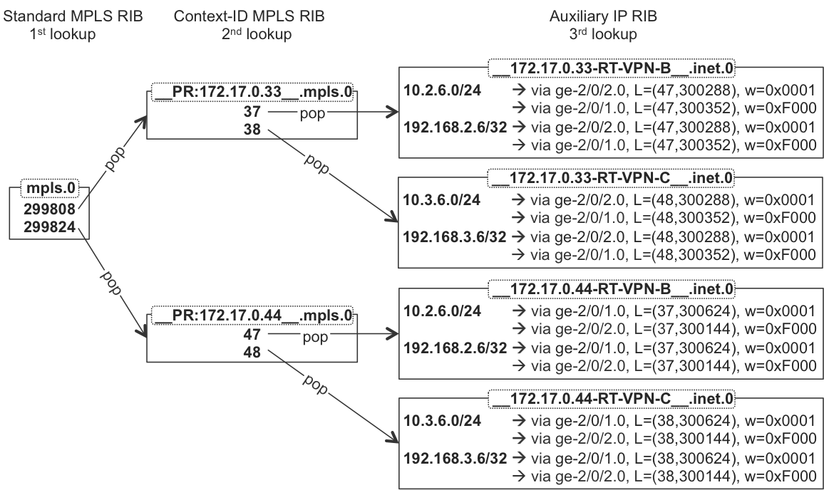
OK, let’s now verify (Figure 21-4, Example 21-15) the multilevel, multifamily (MPLS and IP) RIB/FIB structures created on the protector node PR and used for VPN label translation.
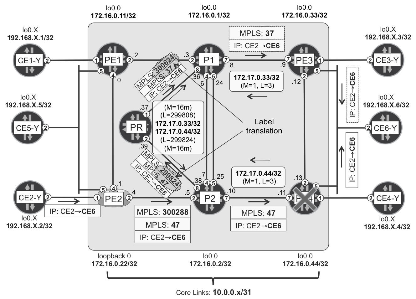
Figure 21-4. RIB structures on a standalone protector node—PR (Junos)
Both egress PEs (PE3 and PE4) advertise two multihomed prefixes within each VRF. PE3 uses label 37 for VRF-B, and label 38 for VRF-C, whereas PE4 uses label 47 and 48, respectively. Therefore, the protector node PR translates VPN label 37 to VPN label 47 (and back) as well as VPN label 38 to VPN label 48 (and back). Labels are allocated dynamically, so it might even happen that VPN labels advertised by both PE3 and PE4 are equal. Nevertheless, the protector node always performs translation, even between numerically equal VPN labels.
We can verify with operational commands if the RIB structure outlined in previous figure is correct.
Example 21-15. RIB structures on standalone protector node—PR (Junos)
1     juniper@PR> show ldp database session 172.16.0.1 | find .. | match ..
2      299808      172.17.0.33/32
3      299824      172.17.0.44/32
4
5     juniper@PR> show route table mpls.0
6     (...)
7     299808(S=0)        *[LDP/0] 23:50:07
8                           to table __172.17.0.33__.mpls.0
9     299824(S=0)        *[LDP/0] 3d 02:17:52
10                          to table __172.17.0.44__.mpls.0
11
12    juniper@PR> show route receive-protocol bgp 172.16.0.201
13                next-hop 172.17.0.33 detail | match label
14         VPN Label: 37
15         VPN Label: 37
16         VPN Label: 38
17         VPN Label: 38
18
19    juniper@PR> show route receive-protocol bgp 172.16.0.201
20                next-hop 172.17.0.44 detail | match label
21         VPN Label: 47
22         VPN Label: 47
23         VPN Label: 48
24         VPN Label: 48
25
26    juniper@PR> show route table __172.17.0.
27
28    __172.17.0.33__.mpls.0: 2 destinations, 2 routes (2 active, ...)
29    + = Active Route, - = Last Active, * = Both
30
31    37                 *[Egress-Protection/170] 23:29:45
32                          to table __172.17.0.33-RT-VPN-B__.inet.0
33    38                 *[Egress-Protection/170] 23:29:45
34                          to table __172.17.0.33-RT-VPN-C__.inet.0
35
36    __172.17.0.44__.mpls.0: 2 destinations, 2 routes (2 active, )
37    + = Active Route, - = Last Active, * = Both
38
39    47                 *[Egress-Protection/170] 23:11:43
40                          to table __172.17.0.44-RT-VPN-B__.inet.0
41    48                 *[Egress-Protection/170] 23:11:43
42                          to table __172.17.0.44-RT-VPN-C__.inet.0
43
44    juniper@PR> show route table __172.17.0.33-RT-VPN-B__.inet.0 detail |
45                match "entry|weight|operation|Protocol next hop"
46    10.2.6.0/24 (1 entry, 1 announced)
47                Next hop: 10.0.0.38 via ge-2/0/2.0 weight 0x1, selected
48                Label operation: Push 47, Push 300288(top)
49                Next hop: 10.0.0.36 via ge-2/0/8.0 weight 0xf000
50                Label operation: Push 47, Push 300352(top)
51                Protocol next hop: 172.17.0.44
52    192.168.2.6/32 (1 entry, 1 announced)
53                Next hop: 10.0.0.38 via ge-2/0/2.0 weight 0x1, selected
54                Label operation: Push 47, Push 300288(top)
55                Next hop: 10.0.0.36 via ge-2/0/8.0 weight 0xf000
56                Label operation: Push 47, Push 300352(top)
57                Protocol next hop: 172.17.0.44
58
59    juniper@PR> show route table __172.17.0.44-RT-VPN-B__.inet.0 detail |
60                match "entry|weight|operation|Protocol next hop"
61    10.2.6.0/24 (1 entry, 1 announced)
62                Next hop: 10.0.0.36 via ge-2/0/8.0 weight 0x1, selected
63                Label operation: Push 37, Push 300624(top)
64                Next hop: 10.0.0.38 via ge-2/0/2.0 weight 0xf000
65                Label operation: Push 37, Push 300144(top)
66                Protocol next hop: 172.17.0.33
67    192.168.2.6/32 (1 entry, 1 announced)
68                Next hop: 10.0.0.36 via ge-2/0/8.0 weight 0x1, selected
69                Label operation: Push 37, Push 300624(top)
70                Next hop: 10.0.0.38 via ge-2/0/2.0 weight 0xf000
71                Label operation: Push 37, Push 300144(top)
72                Protocol next hop: 172.17.0.33
Unless stated otherwise, all of the line numbers in the following three paragraphs correspond to Example 21-15. The PR node advertises real labels for its locally configured protector context-IDs (lines 2 and 3). And, as expected, these labels match the labels already observed in earlier verifications (Example 21-13, lines 39 and 46). Similar to the combined protector/backup egress PE case, the label associated with the protector context-ID points to a context label table. But in this case, the two protector context-IDs are configured on the PR, and the PR creates two context label tables (lines 8 and 10): one table for each context-ID.
The PR extracts VPN labels from the received NLRIs (lines 12 through 24) and, based on the BGP protocol next hop, places these VPN labels in the appropriate context label table (lines 26 through 42). VPN labels, on the other hand, point to the appropriate auxiliary IP tables, based on the RTs associated with the NLRI. The difference between the previous case (combined protector/backup egress PE) and the current case is that the name (lines 32, 34, 40, and 42) of these auxiliary IP tables is now based on configured route-target names (Example 21-11, lines 24 and 25), and no longer on VRF names. The separate protector node does not contain any VRFs, as already mentioned.
The auxiliary IP tables contain VPN prefixes advertised by the backup egress PE. How is the backup egress PE determined? For example, for NLRIs with BGP protocol next hop 172.17.0.33 (the primary context-ID of PE3), the backup NLRIs have a different BGP protocol next hop. If you look carefully, you will realize that the auxiliary table __172.17.0.33-RT-VPN-B__.inet.0 contains prefixes with the BGP protocol next hop 172.17.0.44 (lines 51 and 57), whereas table __172.17.0.44-RT-VPN-B__.inet.0 is just the opposite: with the BGP protocol next hop 172.17.0.33 (lines 66 and 72). Of course, these auxiliary IP tables contain new label stacks, including the VPN label assigned by the backup egress PE, and the transport label to reach the backup egress PE. Additionally, in this particular network topology, the protector node connects to the network in a redundant way (two links); therefore, two direct next hops to reach the backup egress PE can be found in the auxiliary IP tables: the primary and the LFA backup.
Now, when PE3 fails, P1 redirects (using the preinstalled LFA backup next hop) traffic originally flowing via the PE2→P1→PE3 path to the PR. The PR performs label translation based on previously discussed RIB structures. Subsequently, the PR sends the traffic (with the VPN label assigned by PE4) via the PR→P2→PE4 path. PE4 has no clue that anything out of the ordinary has happened on the network. From the perspective of PE4, the received packet (redirected by P1 and translated by the PR) looks like a normal VPN packet with the VPN label assigned by PE4. This confirms that no special feature support is required on the PE nodes in centralized protector designs. All the required intelligence is limited to the protector node.
Context-ID Advertisement Methods
In all the discussions so far about egress protection (service mirroring), IS-IS was distributing context-IDs as some sort of links. To be more precise, both primary and protector context-IDs were distributed via TLV 135 (Extended IP Reachability), as already verified in lines 4 and 7 in Example 21-3. In addition, label bindings for these context-IDs were distributed via LDP (implicit null label for primary context-ID, and real label for protector context-ID). Therefore, this method of announcing context-IDs in IGP is called stub-link. In general, there are three methods of distributing context-ID information:
Stub-Link
The primary context-ID is advertised as a stub-link in the IS-IS database: Extended IP Reachability (TLV type 135). Label binding for primary context-ID (implicit null) is advertised via LDP.
The protector context-ID is advertised as a stub-link in the IS-IS database: Extended IP Reachability (TLV type 135). Label binding for protector context-ID (real label) is advertised via LDP.
Stub-alias
The primary context-ID is advertised as a stub-link in the IS-IS database: IP Interface Address (TLV type 132) and Extended IP Reachability (TLV type 135). Label binding for primary context-ID (implicit null label) is advertised via LDP.
The protector context-ID is advertised as an IPv4 FEC label binding element: SID/Label Binding (TLV type 149). Thus, label-binding for protector context-ID (real label) is advertised via IS-IS, not via LDP.
Stub-proxy
The primary context-ID is advertised as a virtual context-ID node in the IS-IS database: Extended IS Reachability (TLV type 22) from primary egress PE to virtual context-ID node + virtual context-ID node with a complete set of TLVs (TLV: 1, 14, 129, 132, 134, 135, 137 and two TLVs type 22). Label binding for primary context-ID (implicit null label) is advertised via LDP.
The protector context-ID is advertised as a link to the virtual context-ID node in IS-IS: Extended IS Reachability (TLV type 22) from protector to virtual context-ID node. Label binding for protector context-ID (real label) is advertised via LDP.
Note that the stub-link advertisement method has already been discussed in detail in previous sections; therefore, the following section will concentrate on the stub-alias and stub-proxy methods.
Note
As of this writing, all three methods for advertising context-IDs were supported by IS-IS in Junos. However, OSPF support was limited to the stub-link method only, where the context-ID is advertised as a stub network (Type 3).
Stub-Alias
The stub-link advertisement method has certain limitations, because it greatly depends on the network topology to provide backup coverage for the context-ID. For example, if in the topology outlined in Figure 21-1 the cross-links (PE1-P2 and PE2-P1) are temporarily disabled, P2 has no backup coverage for context-ID 172.17.0.22, as you can see here:
Example 21-16. LFA state for context-ID 172.17.0.22 with stub-link on P2 (Junos)
1     juniper@P2> show ldp database session 172.16.0.22 |
2                 find Output | match 172.17.0.22
3      299824      172.17.0.22/32
4
5     juniper@P2> show route label 299824 table mpls.0 | find S=0
6     299824(S=0)        *[LDP/9] 00:20:10, metric 20
7                         > to 10.0.0.4 via ge-2/0/2.0, Pop
The obvious reason for this situation is the lack of a loop-free backup LFA path. You can, eventually, manipulate the metric of the context-ID advertised by the protector node (PE1), or implement some more advanced LFA extensions (R-LFA, TI-FRR) discussed earlier. Fortunately, there is another option: the protector node (PE1) can advertise the context-ID in stub-alias mode.
You can enable the stub-alias method by using the stub-alias keyword, as shown in Example 21-17. The stub-alias method uses the new IS-IS TLV type 149: SID/Label Binding TLV, as defined in draft-previdi-isis-segment-routing-extensions, Section 2.4. This TLV includes the MPLS label that the PLR should use when redirecting the traffic to the protector. However, the transport label the PLR uses to reach the protector is still the traditional LDP label associated with the normal loopback of the protector node.
Example 21-17. Context-ID stub-alias configuration on PE1 (Junos)
Example 21-18. LFA state for context-ID 172.17.0.22 with stub-alias on P2 (Junos)
1     juniper@P2> show isis database PE1 detail | match FEC
2        IP FEC: 172.17.0.22/32               Label:    331776 Mirror
3
4     juniper@P2> show route 172.17.0.22/32 table inet.5
5     (...)
6     172.17.0.22/32
7          *[IS-IS/18] 00:01:32, metric 11, metric2 20
8             to 10.0.0.6 via ge-2/0/4.0, Push 331776, Push 300064(top)
9           > to 10.0.0.24 via ge-2/0/5.0, Push 331776, Push 300064(top)
10
11    juniper@P2> show ldp database session 172.16.0.1 | match <pattern>
12    Input label database, 172.16.0.2:0--172.16.0.1:0
13     300064      172.16.0.11/32
14    Output label database, 172.16.0.2:0--172.16.0.1:0
15     299984      172.16.0.11/32
16
17    juniper@P2> show route 172.17.0.22/32 table inet.0
18    (...)
19    172.17.0.22/32     *[IS-IS/18] 02:51:07, metric 11
20                        > to 10.0.0.4 via ge-2/0/2.0
21
22    juniper@P2> show route 172.17.0.22/32 table inet.3
23    (...)
24    172.17.0.22/32     *[LDP/9] 02:49:45, metric 11
25                        > to 10.0.0.4 via ge-2/0/2.0
26
27    juniper@P2> show route label 299824 table mpls.0 | find S=0
28    299824(S=0) *[LDP/9] 02:34:13, metric 11, metric2 20
29      > to 10.0.0.4 via ge-2/0/2.0, Pop
30        to 10.0.0.6 via ge-2/0/4.0, Swap 331776, Push 300064(top)
31        to 10.0.0.24 via ge-2/0/5.0, Swap 331776, Push 300064(top)
As a result of enabling the stub-alias advertisement mode, PE1 stops advertising the protector context-ID via IS-IS TLV 135 and via LDP. Instead, only IS-IS TLV 149 is used (line 2), which includes both the IP prefix and corresponding label. Based on this information, all routers in the network create routing entries in the new RIB, called inet.5 (lines 4 through 9). The bottom label of this entry is the label advertised in TLV 149, whereas the top label is the transport (LDP) label associated with the originator of TLV 149: the PE1 loopback (line 13). The mirror label is quasi-tunneled inside the LDP tunnel toward PE1.
P2 can reach the PE1 loopback via PE2 or P1 with equal cost (remember, cross-links are temporarily disabled). However, PE2 is the primary node for 172.17.0.22; therefore, P2 installs the path avoiding PE2 to reach 172.17.0.22 in inet.5. Conversely, tables inet.0 and inet.3 have standard entries (lines 17 through 25) not affected by the new TLV 149.
Note
inet.5 is, like inet.3, an auxiliary RIB; therefore, it has no corresponding FIB and its entries are not used (natively) for traffic forwarding.
The trick now is with the entry for the local label bound to the context-ID 172.17.0.22. If you compare lines 5 through 7 in Example 21-16 with lines 27 through 31 in Example 21-18, you can spot the differences. The primary next hop (line 29) is toward PE2, but there are also two backup next hops (parallel links) pointing to P1 (lines 30 and 31). P2 borrows the label stack for these backup next hops from the inet.5 RIB table.
Now when PE2 fails, labeled traffic is protected, whereas native IP traffic is not. P2 redirects the labeled traffic to P1 based on the preinstalled backup next hops found in the mpls.0 RIB (and corresponding FIB) table. P1 removes the top label, and finally, traffic arrives to PE1 with the mirror label (advertised via TLV 149) on the top.
The rest of the story is the same. The protector node uses RIB/FIB structures (similar to those outlined in Figure 21-2) to forward the traffic to the appropriate local CE, based on VPN labels allocated by the primary egress PE. Or, the standalone (centralized) protector node uses RIB/FIB structures similar to those outlined in Figure 21-4 to perform VPN label translation and send the packets to the backup egress PE.
Stub-Proxy
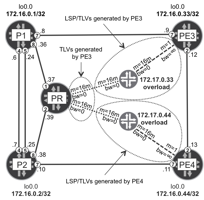
The stub-proxy advertisement method brings a completely new approach. Instead of adding some TLVs here or there, with the stub-proxy method, a completely new IS-IS node is injected into the IS-IS database (Figure 21-5). Of course, it is not a real node, just an emulated one. However, from the point of view of the other routers (e.g., PLR) it looks like a real node, with the IP address equal to the context-ID. This emulated context-ID node is dual-homed, with one emulated link connecting to the primary egress PE, and the second emulated link connecting to the protector node.
Figure 21-5. Stub-proxy context ID advertisement mode
Therefore, from the view of other nodes in the network topology, the context-ID IP address can either be reached via the primary egress PE or via the protector node. The emulated context-ID node announces the overload bit, thus it cannot be used for transit traffic. This is good, because in reality there is no connection between the primary egress PE and the protector node via context-ID node—it is all just virtual. Furthermore, the path to reach the emulated context-ID node via the primary egress PE is always preferred over the path via the protector node. For the emulated link connected to the emulated context-ID node, the primary egress PE announces good link characteristics (low metric, high bandwidth), whereas the protector node announces bad link characteristics (high metric, low bandwidth).
Similar to enabling stub-alias mode, you can enable stub-proxy mode on the primary egress PE and on the protector via a single knob, as shown in Example 21-19.
Example 21-19. Context-ID stub-proxy configuration on PE3 (Junos)
So, let’s check what can be observed in the network now.
Example 21-20. Emulated LSPs/TLVs with stub-proxy (Junos)
1     juniper@PE3> show isis database | match 172.17
2     PE3-172.17.0.33.00-00      0x38   0x1453      772 L1 L2 Overload
3     PE4-172.17.0.44.00-00      0x51   0x3b38     1142 L1 L2 Overload
4
5     juniper@PE3> show isis database PE3-172.17.0.33 extensive | find TLVs
6       TLVs:
7         Area address: 49.0000 (3)
8         LSP Buffer Size: 1492
9         Speaks: IP
10        Speaks: IPV6
11        IP router id: 172.17.0.33
12        IP address: 172.17.0.33
13        Hostname: PE3-172.17.0.33
14        IP address: 172.17.0.33
15        IP extended prefix: 172.17.0.33/32 metric 0 up
16        IS extended neighbor: PE3.00, Metric: default 16777214
17          IP address: 172.17.0.33
18          Neighbor's IP address: 172.16.0.33
19          Local interface index: 1, Remote interface index: 2147618817
20          Traffic engineering metric: 16777214
21          Maximum reservable bandwidth: 0bps
22          Maximum bandwidth: 0bps
23        IS extended neighbor: PR.00, Metric: default 16777214
24          IP address: 172.17.0.33
25          Neighbor's IP address: 172.16.0.10
26          Local interface index: 2, Remote interface index: 2147618818
27          Traffic engineering metric: 16777214
28          Maximum reservable bandwidth: 0bps
29          Maximum bandwidth: 0bps
30
31    juniper@PE3> show isis database PE3 extensive | find TLVs
32    (...)
33        IS extended neighbor: PE3-172.17.0.33.00, Metric: default 1
34          IP address: 172.16.0.33
35          Neighbor's IP address: 172.17.0.33
36          Local interface index: 2147618817, Remote interface index: 1
37          Traffic engineering metric: 1
38          Maximum reservable bandwidth: Infbps
39          Maximum bandwidth: Infbps
40
41    juniper@PR> show isis database PR extensive | find TLVs
42    (...)
43       IS extended neighbor: PE3-172.17.0.33.00, Metric: default 16777214
44          IP address: 172.16.0.10
45          Neighbor's IP address: 172.17.0.33
46          Local interface index: 2147618818, Remote interface index: 2
47          Traffic engineering metric: 16777214
48          Maximum reservable bandwidth: 0bps
49          Maximum bandwidth: 0bps
50    (...)
51       IS extended neighbor: PE4-172.17.0.44.00, Metric: default 16777214
52          IP address: 172.16.0.10
53          Neighbor's IP address: 172.17.0.44
54          Local interface index: 2147618818, Remote interface index: 2
55          Traffic engineering metric: 16777214
56          Maximum reservable bandwidth: 0bps
57          Maximum bandwidth: 0bps
After enabling stub-proxy on the primary egress PEs, you will realize that the additional IS-IS nodes appear in the IS-IS database (lines 2 and 3). The names of these nodes are derived from the real node (PE3 or PE4) and corresponding context-ID associated for each real node (172.17.0.33 and 172.17.0.44). In reality, of course, there are no new nodes! PE3 and PE4 are cheating, injecting not only their normal LSP, but also the LSP for the emulated context-ID node, as well. As discussed, the overload bit is set, so the emulated context-ID nodes cannot be used for transit.
Now, if you check the content for one of the emulated context-ID nodes, you’ll see plenty of TLVs announced (lines 7 through 16, and 23)—just like in a normal IS-IS node. There are two emulated links (neighbors): the primary egress PE (line 16), and the protector (line 23). In addition to the overload bit, other characteristics (metric and bandwidth) of these emulated links are bad (lines 20 through 22, and 27 through 29): metric high, bandwidth zero. This is just to ensure that no one tries to use this emulated node for transit.
Additionally, the primary egress PEs generate extra Extended IS Reachability (TLV type 22) for the emulated link toward the emulated context-ID node. This time the link from the primary egress PE to the emulated context-ID node has good characteristics (lines 37 through 39): low metric and high (infinite) bandwidth.
After enabling stub-proxy mode on the protector, the protector also generates additional Extended IS Reachability (TLV type 22) for each emulated link toward each emulated context-ID node. As you can see, the metrics (both default and TE metric) for these links are set to a large value, whereas bandwidth is set to 0 (lines 47 through 49 and 55 through 57). So, basically, these links will be treated as a last resort, when other routers in the network perform CSPF calculations to reach the emulated context-ID node.
Note
As of this writing, Junos only supported stub-proxy mode with RSVP-TE.
Because stub-proxy mode is not supported with LDP, let’s configure the RSVP tunnels from the Junos ingress PE: PE1, as provided in Example 21-21.
Note
By default, IOS XR does not allow RSVP-TE tunnels destined to an IS-IS node in overload state. Configuring path-selection ignore overload under mpls traffic-eng stanza disables that check.
Example 21-21. RSVP tunnel configuration on ingress PE (Junos)
The RSVP-TE tunnel configuration on ingress PE is pretty standard. The important feature that must be enabled is facility backup (node-link-protection), because this feature accommodates local repair–style redirection of traffic at the PLR in case of primary egress PE failure. The destination address this time is actually context-ID, not the loopback of egress PE. Similarly, the tunnel, destined also to the context-ID, must be created on the protector node, too, in order to resolve BGP protocol next-hop addresses.
Let’s verify RIB/FIB states on the path from the ingress PE (PE1) to the protector (PR), as illustrated in Example 21-22.
Example 21-22. RIB/FIB states between ingress PE and protector with stub-proxy
1     juniper#PE1> show mpls lsp name PE1--->PE3-CTX detail | find RRO
2         Received RRO (ProtectionFlag 1=Available 2=InUse 4=B/W 8=Node
3                       10=SoftPreempt 20=Node-ID):
4               172.16.0.1(flag=0x29) 10.0.0.3(flag=9 Label=300752)
5               172.16.0.33(flag=0x20) 10.0.0.9(Label=3)
6               172.17.0.33(flag=0x20) 172.17.0.33(Label=3)
7
8     juniper#P1> show route label 300752 | find S=0
9     300752(S=0) *[RSVP/7/1] 00:09:05, metric 1
10                 > to 10.0.0.9 via ge-2/0/7.0,
11                      label-switched-path PE1--->PE3-CTX
12                   to 10.0.0.37 via ge-2/0/8.0,
13                      label-switched-path Bypass->10.0.0.9->172.17.0.33
14
15    juniper#P1> show route forwarding-table label 300752 | find S=0
16    Destination  Type  Next hop    Type         Index     Netif
17    300752(S=0)  user              ulst         1048578
18                       10.0.0.9    Pop          1644      ge-2/0/7.0
19                       10.0.0.37   Swap 300432  1700      ge-2/0/8.0
20
21    juniper#PR> show route label 300432 | find S=0
22    300432(S=0)        *[MPLS/0] 00:26:35
23                          to table __172.17.0.33__.mpls.0
As you can see, verification shows that the RSVP-TE tunnel destined to the context-ID of PE3 is established via the PE1→P1→PE3 path (lines 4 through 6). The label used at the second hop (P1) is 300752. Now, by looking at the forwarding entry on P1, packets arriving with this label use the primary next hop PE3 (line 10) with label action pop (line 18). In case of PE3 failure, packets are forwarded via the node protection bypass (line 13) toward the PR with label action swap (line 19). So far, everything is normal and matches the behavior described in Chapter 19, in which the RSVP-TE facility backup was described in detail.
Now, packets with label 300432 (forwarded via the node protection bypass terminated on context-ID 172.17.0.33) arrive at the PR. And what happens? The PR intercepts these packets using egress protection (service mirroring) RIB/FIB structures (lines 21 through 23)! Why? When the node protection bypass destined to the emulated context-ID node is established via the PR node the PR node actually cheats! As discussed, the emulated context-ID node is not a real node. Therefore, forwarding traffic to that node doesn’t make sense. The label from the node protection bypass is actually the context label causing the arriving traffic to perform a lookup on the context label table, as discussed in all the previous cases.
Let’s check the details of Explicit Route Object (ERO) and the Record Route object (RRO), as shown in the Example 21-23.
Example 21-23. Node protection bypass ERO and RRO on PLR (Junos)
1     juniper#P1> show rsvp session name Bypass->10.0.0.9->172.17.0.33
2                 detail | match " route:"
3       Explct route: 10.0.0.37 172.17.0.33 (link-id=2)
4       Record route: <self> 10.0.0.37
When you carefully examine the ERO and the RRO information of the node protection bypass, you can actually spot that there is something unusual with this bypass. Namely, whereas the ERO (line 3) contains two links (P1 believes 172.17.0.33 is two links away, based on IS-IS database content), RRO (line 4) lists only a single link, which is, in fact, the only link present.
Note
Junos supports egress protection (service mirroring) with LDP using the stub-link or stub-alias mode, and with RSVP-TE, using all three modes: stub-link, stub-alias, and stub-proxy.
L3VPN PE→CE Egress Link Protection
All discussions so far in this chapter concentrate on fast traffic restoration during failure of the egress PE node. The last failure type is, however, failure of the egress PE→CE link. Link failure is a more likely event than node failure, especially when the AC is connected to a long-distance link. Let’s investigate what you can do to optimize failover times during such failures.
Junos calls this type of protection Link Protection with Host Fast ReRoute (HFRR) for protecting directly connected prefixes on broadcast interfaces, like Ethernet. Or simply Provider Edge Link Protection for other types of PE-CE prefixes (e.g., eBGP). IOS XR calls it BGP PIC Edge PE-CE Link Protection. Regardless of the terminology, the goal is the same: to preinstall in the FIB the backup next hop that can be used during failure of a primary PE→CE link.
Looking back at Figure 21-1 you can see dual-homed CEs connected to the PE1/PE2 pair as well as to the PE3/PE4 pair. If traffic destined to the CE5 arrives from the MPLS core at PE2, it is forwarded over the direct PE2→CE5 link. Now, when this link fails, ingress PE (PE3 or PE4) must wait for the BGP update from PE2, which withdraws the CE5 prefix. Only after that can the ingress PE switch to another egress PE (PE1). This process is relatively long (it can take seconds in a scaled environment) because it involves BGP convergence.
You can optimize this behavior if per-VRF aggregated label assignment is enabled on PE2. In that case, PE2 performs IP lookup inside VRF for packets arrived over an MPLS cloud. Therefore, as soon as PE2 updates its RIB (and subsequently FIB) to use the route from PE1 to reach CE5, traffic can be redirected by PE2 to PE1. However, this is still not sub-100 millisecond failover, because a new next hop must be determined and installed in HW FIB after PE→CE link failure.
Previously discussed techniques do not help now, because they rely on egress PE node failure. Here, it is not the egress PE node that fails, but the egress PE→CE link. So, let’s enable protection for this type of failure. In IOS XR, you don’t need to do anything, if the BGP PIC Edge is already enabled. The configuration shown in Example 20-11 in the previoius chapter actually enables protection against both egress PE node and egress PE→CE link failure. In Junos, however, you need to enable this feature explicitly on a per PE-CE protocol basis. Following shows how you can do it for directly connected hosts and for eBGP routes:
Example 21-24. Link protection with HFRR for direct routes on PE1 (Junos)
In the test topology, PE-CE link protection for only VRF-B has been enabled. Therefore, you will be able to see the differences in the FIB structures for VRF-B (PE-CE link protection enabled) and VRF-C (PE-CE link protection not enabled).
Nothing specific happened in the VRF-C (lines 1 and 2). Host route (/32) toward CE5-C is not present in the VRF-C table. The CE5-C host can still be resolved (not shown for brevity) via LAN prefix (10.3.5.0/24), as usual.
Conversely, in the VRF-B, we can observe some interesting things. The CE5-B host is now reachable via two new protocols: Address Resolution Protocol (ARP) (line 5) and Fast ReRoute (FRR) (line 7). The feature name, Host Fast ReRoute, is derived from the fact that now the host routes—with corresponding fast reroute backup next-hops—are created in the RIB/FIB structures. The ARP entry is a result of the ARP machinery that discovers MAC addresses for each host (line 16). The router only uses this entry on the control plane, however not for forwarding (observe mark @ and Unusable). Instead, the FRR entry is used for traffic forwarding (observe mark #) and is the basis for next-hop structures created in the FIB.
In the RIB/FIB, you can see that the hierarchical next-hop structure contains primary (weight=0x1, lines 8, 16 through 18, and 35) direct unicast next hop pointing to CE5-B. The unilist backup next hop (weight 0x4000, lines 22, 23, and 38) contains two direct unicast next hops: the direct MPLS link from PE1 to PE2 (lines 9, 24 through 26, and 39) and the link via the MPLS cloud as backup (lines 10, 27 through 29, and 40). Therefore, when the PE1→CE5 link fails, the direct unicast next hop (line 35) is removed, and traffic can be immediately forwarded via the preinstalled backup next hops pointing to the MPLS network.
Note
As of this writing, Junos doesn’t support PE-CE link protection for static routes. Hence, CE5-B’s loopback address (192.168.2.5) is not protected by the PE-CE link-protection feature on PE1.
After checking PE1 (Junos), let’s now verify PE2 (IOS XR).
Example 21-27. BGP PIC Edge PE-CE link protection on PE2 (IOS XR)
1     RP/0/RSP0/CPU0:PE2#show cef vrf VRF-C 192.168.3.5/32 |
2                        include "  via|labels"
3        via 10.3.5.5, 3 dependencies, recursive [flags 0x0]
4          next hop 10.3.5.5/32 Gi0/0/0/5.3 labels imposed {None}
5
6     RP/0/RSP0/CPU0:PE2#show cef vrf VRF-B 192.168.2.5/32 |
7                        include "  via|labels"
8        via 10.2.5.5, 3 dependencies, recursive [flags 0x0]
9          next hop 10.2.5.5/32 Gi0/0/0/5.2 labels imposed {None}
10       via 172.16.0.11, 7 dependencies, recursive, backup [flags 0x6100]
11         next hop 10.0.0.0/32 Gi0/0/0/0 labels imposed {ImplNull 17}
Similar to the Junos case, VRF-C contains only a single next hop. However, in VRF-B, IOS XR installs the primary next hop pointing to the direct PE2→CE5 link and it also installs the backup next hop pointing to the MPLS cloud. As discussed earlier, PE1 can be reached from PE2 via two next hops: the primary and the LFA backup. However, only the primary is shown in CEF VRF entries. You would need to use the internal keyword to display full CEF structure (omitted here for brevity).
Note
As of this writing, IOS XR doesn’t support PE-CE link protection for directly connected host routes. Hence, the CE5-B interface address (10.2.5.5) is not protected by PE-CE link-protection feature on PE2.
Verifying PE-CE link protection for the BGP routes on PE3 (see Example 21-28) confirms that hierarchical next-hop structures, similar to structures observed in Example 21-26, are used to provide local repair during PE3→CE6 link failure.
Example 21-28. BGP PE-CE link protection states on PE3 (Junos)
1     juniper@PE3> show route table VRF-B 192.168.2.6/32
2     @ = Routing Use Only, # = Forwarding Use Only
3     192.168.2.6/32
4             @[BGP/170] 19:53:29, MED 0, localpref 100
5                AS path: 65506 ?, validation-state: unverified
6              > to 10.2.6.6 via ge-2/0/5.2
7              [BGP/170] 19:53:02, MED 0, localpref 100, from 172.16.0.201
8                AS path: 65506 ?, validation-state: unverified
9              > to 10.0.0.13 via ge-2/0/2.0, Push 17
10             [BGP/170] 19:52:58, MED 0, localpref 100, from 172.16.0.202
11               AS path: 65506 ?, validation-state: unverified
12             > to 10.0.0.13 via ge-2/0/2.0, Push 17
13            #[Multipath/255] 13:42:11, metric 0
14             > to 10.2.6.6 via ge-2/0/5.2
15               to 10.0.0.13 via ge-2/0/2.0, Push 17
16
17    juniper@PE3> show route forwarding-table destination 192.168.2.6/32
18                 extensive | match <pattern>
19
20    Destination:  192.168.2.6/32
21      Next-hop type: unilist               Index: 1048743  Reference: 2
22      Nexthop: 10.2.6.6
23      Next-hop type: unicast               Index: 1613     Reference: 5
24      Next-hop interface: ge-2/0/5.2    Weight: 0x1        Uflags: 0x2
25      Nexthop:
26      Next-hop type: composite             Index: 1894     Reference: 2
27      Next-hop type: indirect              Index: 1048742  Reference: 2
28                                        Weight: 0x4000
29      Nexthop: 10.0.0.13
30      Next-hop type: unicast               Index: 1811     Reference: 3
31      Next-hop interface: ge-2/0/2.0    Weight: 0x4000
32
33    juniper@PE3> request pfe execute target fpc2 command
34                 "show nhdb id 1048743 recursive"
35    (...)
36    GOT: 1048743(Unilist, IPv4, ifl:0:-, pfe-id:0)
37    GOT:  1613(Unicast, IPv4, ifl:419:ge-2/0/5.2, pfe-id:0)
38    GOT:  1894(Compst, IPv4->MPLS, ifl:0:-, pfe-id:0, comp-fn:Chain)
39    GOT:    1048742(Indirect, IPv4, ifl:413:ge-2/0/2.0, pfe-id:0,i-ifl:0)
40    GOT:      1811(Unicast, IPv4, ifl:413:ge-2/0/2.0, pfe-id:0)
OK, it looks like RIB/FIB states are now prepared to handle a PE→CE link failure with local repair–style protection: the backup next hops are preinstalled in the HW FIB. Some attention, however, is required on a loop issue.
With PE-CE link protection deployed on the pair of PEs, a loop can occur during failure of the multihomed CE or during the simultaneous failure of PE-CE links (on both PEs) toward the multihomed CE. This loop is unavoidable. When one PE detects failure of the connected PE→CE link, it removes the corresponding primary next hop and redirects the traffic destined for the multihomed CE toward the second PE. When the traffic arrives at the second PE, the primary next hop is missing, too. Consequently, a second PE redirects the traffic back to the first PE based on a still valid backup next hop. This loop can continue until BGP from both PEs learns that the CE is down and they withdraw their BGP routes.
Layer 2 VPN Service Mirroring
You should have learned by now the general concept of egress protection (service mirroring) with L3VPN services. Similar to L3VPN services, these concepts can be deployed for BGP and LDP-based Layer 2 VPN (L2VPN) services. There are, however, some specific aspects that relate to L2VPN services.
BGP-Based L2VPN Service Mirroring
Let’s begin with the BGP-based L2VPN, where BGP is used for autodiscovery and signaling. You should be familiar with basic multihomed BGP L2VPN operations from Chapter 6. Now, you will enhance multihomed BGP L2VPN architecture to ensure fast traffic restoration based on egress-protection (service mirroring) concepts.
Following the topology outlined in Figure 20-1 at the beginning of the Chapter 20, let’s create two multihomed point-to-point BGP L2VPNs, using standard configurations discussed in Chapter 6:
L2VPN-F
This includes CE1-F (connected to PE1) and CE6-F (connected to PE3/PE4 pair, where PE3 is the primary PE, and PE4 is the protector/backup PE)
L2VPN-G
This includes CE2-G (connected to PE2) and CE6-G (connected to PE3/P4 pair, where PE3 is the protector/backup PE, and PE4 is the primary PE)
Note
As of this writing, Junos supports BGP L2VPN egress-protection (service mirroring) using only combined protector/backup PE architecture.
So for example, let’s extend L2VPN-G for egress-protection to provide fast traffic restoration in the case of primary PE (PE4) failure. On the ingress PE (PE2, IOS XR) no configuration changes are required. Example 21-29 and Example 21-30 present the full configurations with egress-protection extensions for PE4 and PE3, respectively.
Example 21-29. Egress-protected multihomed BGP L2VPN, primary PE4 (Junos)
Context-ID must be configured on the primary PE as primary (Example 21-29, lines 2 through 6) and on the protector/backup PE as protector (Example 21-30, lines 2 through 6). Because the previously deployed egress protection for L3VPN used separate (centralized) mode (protector function was not deployed on either PE3 or PE4), you now use a different context-ID. The primary PE uses this context-ID to set the BGP protocol next hop during routing-instance export (Example 21-29, line 16), whereas the protector/backup PE uses this context-ID for egress-protection functions activated by the hot-standby keyword (Example 21-30, line 25).
Note that you can set the BGP protocol next hop to context-ID by using different options:
Via BGP export policy applied to multiprotocol BGP neighbor or group
Via routing-instance (L3VPN or L2VPN) egress-protection context-ID configuration
Via routing-instance (L3VPN or L2VPN) export policy
Via egress-protection context-ID configuration in BGP address family (inet-vpn unicast or l2vpn signaling)
All options are applicable to both L3VPN and L2VPN deployments. The first option (BGP neighbor export policy) was used in the L3VPN examples in the previous section. It provides more granularity because you can set the BGP protocol next hop only to specific prefixes. In L2VPN deployments, you typically don’t need such granularity, so the second option is used in this section’s examples. Other options could be used, as well. However, because of limited space in this book, we will leave those to you to explore.
What’s next? Similar to the L3VPN case, you need to enable egress-protection functionality in the appropriate address family (lines 7 through 11 in Examples Example 21-29 and Example 21-30). And that’s it—you are done! The rest is standard multihomed L2VPN configuration (discussed in Chapter 6), and is repeated here just so you can see the egress-protection configuration from a full multihomed L2VPN perspective (Example 21-31).
Example 21-31. BGP L2VPN verification on ingress PE (IOS XR)
1     RP/0/RSP0/CPU0:PE2#show l2vpn xconnect group PE3-PE4
2                        xc-name CE6-G.2:6 detail | include <pattern>
3       PW: neighbor 172.18.0.44, PW ID 131078, state is up ( established )
4           MPLS         Local                          Remote
5           Label        36810                          800003
6           CE-ID        2                              6
7
8     RP/0/RSP0/CPU0:PE2#show cef 172.18.0.44 | include "via|label"
9      via 10.0.0.27, Gi0/0/0/3, 3 dependencies, weight 0,class 0, backup
10       local label 16000      labels imposed {317040}
11     via 10.0.0.5, Gi0/0/0/5, 8 dependencies, weight 0,class 0, protected
12       local label 16000      labels imposed {304384}
Verification on the ingress PE shows the expected results. As anticipated, the ingress PE sees the context-ID as next hop (line 3) and therefore uses the LDP transport label associated with that context-ID address to forward frames over this L2VPN. Again, due to the LFA backup, you can see the two direct next hops in the FIB (lines 8 through 12).
The story is the same now with LFA protection for the context-ID as in the case of L3VPN egress protection. In fact, the PLR (P2 router in the topology outlined in Figure 21-3) is not even aware of the type of traffic forwarded using the transport label associated with context-ID 172.18.0.44. The PLR (P2) simply does LFA-style redirection to PE3 during failure of PE4. So, following PE4 failure, traffic arrives at PE3, with some label assigned by PE3 to the protector context-ID 172.18.0.44. Let’s check what happens now.
Example 21-32. BGP L2VPN verification on protector/backup egress PE (Junos)
1     juniper@PE3> show ldp database session 172.16.0.2 | find .. | match ..
2      300688      172.18.0.44/32
3
4     juniper@PE3> show route label 300688 table mpls.0
5     (...)
6     300688(S=0)        *[MPLS/0] 01:46:47
7                           to table __172.18.0.44__.mpls.0
8
9     juniper@PE3> show route label 800003 table __172.18.0.44__.mpls.0
10    (...)
11    800003             *[Egress-Protection/170] 01:48:04
12                        > via ge-2/0/5.8, Pop       Offset: 4
13
14    juniper@PE3> show route receive-protocol bgp 172.16.0.201
15                 table L2VPN-G.l2vpn.0 match-prefix 172.16.0.44:107:*
16                 detail | match "entries|base|hop|target"
17    *  172.16.0.44:107:6:1/96 (2 entries, 1 announced)
18         Label-base: 800002, range: 2, status-vector: 0x0, offset: 1
19         Nexthop: 172.18.0.44
20         Communities: target:65000:1007 Layer2-info: encaps: VLAN,
21           control flags:[0x2] Control-Word, mtu: 1500,
22           site preference: 65535
Unless specified otherwise, line numbers in the following three paragraphs refer to Example 21-32. As you can see, the situation is very similar to the L3VPN case. The protector maintains the label table associated with the protector context-ID (line 7). Within that table, it collects labels from other PEs, just like in the L3VPN case. In this particular example, PE4 (the primary egress PE) announces the NLRI (line 17) with RT 65000:1007 (line 20). The RR reflects this NLRI to PE3 (the protector). PE3 verifies that it is for the protector for this egress PE, because the configured protector context-ID matches the next hop in received NLRI (line 19); therefore, it installs the corresponding label in its context-ID label table.
Just to refresh how the actual label is calculated, the PE3 configuration refers to the remote site with ID = 2 (line 27 in Example 21-30). PE4 announces a label block starting with 800002 and for site IDs starting with 1 (offset=1, line 18). Therefore, for (nonexisting) site 1, the label is 800002, whereas the label for site 2 is 800003. You can see this label being installed in the PE3 context-ID label table (lines 11 and 12). This is also the label used by the ingress PE when sending traffic to PE4 (line 5 in Example 21-31).
RT=65000:1007 (line 20) and site-ID=6 (line 17) advertised by PE4, match the local configuration for L2VPN-G on PE3 (lines 18 and 23 in Example 21-30), and therefore PE3 uses the corresponding PE-CE interface (line 12 in Example 21-32 as well as line 27 in Example 21-30) to send redirected traffic to the locally attached multihomed device. Thus, confirming that the states required for egress-protection to work are correct.
Now, similar to the L3VPN case, let’s extend the protection to cover failure of the PE-CE link, as well. Normally, the PE-CE link is not protected. There is only a single next hop (pointing directly to the connected multihomed CE) installed in the FIB. To have PE-CE link protection you need to have a backup next hop, as well, pointing to the backup PE. What do you need to do? You need to create a special RSVP-TE LSP (called Edge Protection LSP) that the primary PE (PE4 in the topology) can use to forward traffic to the backup PE (PE3 in the topology) in case of PE-CE link failure.
Example 21-33. RSVP-TE Edge Protection LSP for PE-CE egress-protection (Junos)
Configuration of such an LSP on the primary PE is pretty simple: you use context-ID (line 4) as the destination and you use the additional knob egress-protection (line 5) to designate this tunnel for egress-protection purposes. That’s it! Let’s see the outcome using verification from Example 21-34.
Example 21-34. Edge Protection LSP states on backup and primary PE (Junos)
1     juniper@PE4> show route label 800003 table mpls.0 detail | match ...
2                     Next hop: via ge-2/0/5.8 weight 0x1, selected
3                     Label operation: Pop       Offset: 4
4                     Next hop: 10.0.0.12 ge-2/0/2.0 weight 0x2
5                     Label-switched-path PE4--->PE3-PROTECT
6                     Label operation: Swap 800003, Push 301136(top)
7
8     juniper@PE3> show route label 301136 | find S=0
9     301136(S=0)        *[MPLS/0] 00:19:30
10                          to table __172.18.0.44__.mpls.0
As a result, the tunnel from the primary PE to the backup PE is established. This tunnel is, in turn, used as the backup next hop (lines 4 through 6) on the primary PE for PE-CE link protection. What is special about this tunnel? It’s missing the implicit null label. The backup PE (PE3) actually assigns the real label (line 6), which then points to the context-ID label table (lines 8 through 10), and the rest of the story is already familiar.
Note
As of this writing, Junos supports PE-CE link protection for L2VPNs using RSVP-TE-based edge protection LSPs. LDP-based and SPRING-based edge protection LSPs are not supported.
LDP-Based L2VPN Service Mirroring
In LDP-based L2VPN deployments, there are no BGP protocol next hops. As you might remember, all egress-protection schemes discussed so far are based on manipulating the BGP protocol next hop, and advertising IP addresses corresponding to manipulated BGP protocol next hops into IGP and MPLS transport (LDP or RSVP-TE). Therefore, fast redirection can be done via LFA or RSVP-TE Facility Protection backup next hops. However, another draft (draft-ietf-pals-endpoint-fast-protection: PW Endpoint Fast Failure Protection) describes egress-protection (service mirroring) architecture adjusted to LDP-based pseudowire (PW) protection requirements.
The context-ID, and LFA or RSVP-TE Facility Protection–style failover during primary egress PE failure remains the same. However, instead of the BGP protocol next-hop manipulation, the ingress PE must now associate the transport tunnel used for transporting frames of a given PW with the context-ID advertised by the primary and protector/backup egress PE pair. As in previous cases, the transport tunnel itself can be signaled via LDP or RSVP-TE.
Note
As of this writing, IOS XR supports LDP-signaled PW association only with arbitrary chosen RSVP-TE signaled transport tunnels, but not with arbitrary chosen LDP-signaled transport tunnels. Conversely, in Junos, association with a mix of arbitrary chosen LDP and RSVP-TE–signaled tunnels is supported.
Another difference, when compared to BGP-signaled L2VPN protection, is the fact that LDP-signaled multihomed L2VPNs can be deployed in revertive or nonrevertive mode. In BGP-based L2VPNs, failover is always revertive: when the primary egress PE restores from failure, traffic always switches back to the primary egress PE. In LDP-based L2VPN, the default behavior is nonrevertive (you can change this default behavior via configuration, if needed). That is, when the primary egress PE restores from failure, the ingress PE still uses the backup egress PE for traffic forwarding until this active PE (the PE that was originally the backup PE) fails.
Why is this difference important? Egress protection is important to protect the active egress PE by redirecting traffic to the available standby egress PE.
In BGP L2VPNs, if both primary and backup egress PEs are available, the primary is always used as the active egress PE, whereas the backup is used as the standby egress PE. Therefore, there is no need to deploy the egress-protection scheme to protect the backup egress PE.
In LDP-based L2VPNs, as already mentioned, you might need to protect both the primary and the backup egress PE, because in nonrevertive mode, your active egress PE can be actually the PE originally designated as the backup PE.
Apart from these two differences (no BGP protocol next hop and egress protection for primary and backup egress PE), the overall concepts remain the same.
Note
As of this writing, Junos supports LDP L2VPN egress protection (service mirroring) using combined protector/backup PE architecture only.
So, let’s configure egress protection for our LDP-based PW that provides connectivity between the single-homed site CE2-I and the multihomed CE6-I site. As the transport, let’s use RSVP-TE tunnels, as IOS XR cannot set arbitrary transport LDP tunnel and this capability is required by the egress protection for LDP signaled PWs. Let’s begin with the configuration of PE2 (IOS XR), where the single-homed CE is connected (Example 21-35).
Example 21-35. LDP PW ingress PE configuration on PE2 (IOS XR)
On the PE attached to the single-homed CE, you deploy almost the same configuration as that used in Chapter 6. However, the difference is that you need to use RSVP-TE tunnels (lines 4 through 12) destined to the context-IDs (line 9) configured on the PEs connected to the multihomed CE. Because there are two egress PEs, you need to define two such RSVP-TE tunnels (only one is shown here for brevity).
Normally, RSVP-TE tunnels can be established to IP addresses represented by TE Router ID TLVs (TLV type 134). As discussed earlier, the context ID is advertised via Extended IP Reachability (TLV type 135). Therefore, CSPF on your IOS XR device will refuse to initialize the RSVP-TE tunnel. You need to cheat a little! How? By using a path option with a loose next-hop (lines 1, 2, and 12). Your loose next-hop is actually a primary loopback (TE Router ID) of the primary PE. Therefore, Constrained Shortest-Path First (CSPF) is now fully satisfied. It is important to note that the request is for node protection desired (line 10), not just for link protection, which is the default in IOS XR with facility protection. Node protection is the key for egress-protection functionality with RSVP-TE as a transport.
You can see a standard LDP-based L2VPN configuration with primary/secondary PWs (lines 23 through 29). The L2VPN, however, refers to special PW-classes (lines 27 and 29) that force the PWs to use specific RSVP-TE tunnels (line 19). Only one of these PW-classes is shown for brevity.
You must extend primary egress PE configuration with specific egress-protection pieces (Example 21-36).
Example 21-36. LDP PW primary egress PE configuration on PE3 (Junos)
You can see the context-ID configuration (line 3) and some extensions to LDP (lines 5 through 7) (they will be discussed later in this section). In LDP-based L2VPN configurations, you can see egress-protection–specific additions in lines 14 through 16. You must specify the IP address of protector/backup egress PE (in this case, it is PE4) and the context-ID used for protecting this L2VPN. As a result of this configuration, PE3 will try to establish targeted LDP sessions to PE4 in order to exchange additional information required for egress protection functionality.
Optionally, you can enable forwarding (line 13) over a PW reported by the ingress PE as hot-standby (PW Status TLV set to 0x20). Similarly, you can enable forwarding over a hot-standby PW on the backup PE, as well. This provides faster traffic switchover during PE failures. However, it also can cause multicast or broadcast traffic duplication in the direction from the multihomed CE6-I to the single-homed CE2-I because both PWs (PE3→PE2 and PE4→PE2) now actively forward traffic.
After configuring the primary egress PE, let’s turn our attention to the configuration of protector/backup egress PE, outlined in Example 21-37.
Example 21-37. LDP PW protector/backup egress PE on PE4 (Junos)
The protector/backup egress PE configuration also contains some egress-protection–related extensions for L2VPN (lines 14 through 16). Specifically, you can list IP addresses of the ingress and primary egress PEs, as well as the VC ID from the ingress to primary egress PE.
OK, that configuration is done, so let’s have a look at the states in the network.
Example 21-38. LDP L2VPN egress-protection states
1     RP/0/RSP0/CPU0:PE2#show l2vpn xconnect group PE3-PE4 xc-name CE6-I
2                        detail | include "PW: |Local|Label|tunnel"
3       PW: neighbor 172.16.0.33, PW ID 926, state is up ( established )
4         Preferred path tunnel TE 1833, fallback enabled
5           MPLS         Local                          Remote
6           Label        16050                          299936
7       PW: neighbor 172.16.0.44, PW ID 926, state is standby ( all ready )
8         Preferred path tunnel TE 1844, fallback enabled
9           MPLS         Local                          Remote
10          Label        16051                          299936
11
12    RP/0/RSP0/CPU0:PE2#show mpls traffic-eng tunnels 1833 detail
13    [...] Resv Info:
14       Record Route:
15        IPv4 172.16.0.2, flags 0x29 (Node-ID, Protection: available, node)
16        IPv4 10.0.0.5, flags 0x9 (Protection: available, node)
17        Label 311152, flags 0x1
18        IPv4 172.16.0.33, flags 0x20 (Node-ID)
19        IPv4 10.0.0.35, flags 0x0
20        Label 3, flags 0x1
21        IPv4 172.18.0.33, flags 0x0
22        Label 3, flags 0x1
23
24    juniper@P2> show route label 311152 detail | find S=0 | match ...
25                 Next hop: 10.0.0.35 via ge-2/0/6.0 weight 0x1, selected
26                 Label-switched-path PE2--->PE3-CTX2
27                 Label operation: Pop
28                 Next hop: 10.0.0.11 via ge-2/0/7.0 weight 0x8001
29                 Label-switched-path Bypass->10.0.0.35->172.18.0.33
30                 Label operation: Swap 301648
31
32    juniper@PE4> show rsvp session name Bypass->10.0.0.35->172.18.0.33 |
33                 match "Label|Bypass"
34    To          From       Labelin Labelout LSPname
35    172.18.0.33 172.16.0.2  301648        3 Bypass->10.0.0.35->172.18.0.33
36
37    juniper@PE4> show route label 301648 | find S=0
38    301648(S=0)        *[MPLS/0] 00:02:57
39                          to table __172.18.0.33__.mpls.0
40
41    juniper@PE4> show route table __172.18.0.33__.mpls.0
42    (...)
43    299920             *[L2CKT/7] 01:10:39
44                        > via ge-2/0/5.8, Pop
45    299936             *[L2CKT/7] 01:10:45
46                        > via ge-2/0/5.9, Pop
47    800000             *[Egress-Protection/170] 01:10:00
48                        > via ge-2/0/5.6, Pop       Offset: 4
The ingress PE (PE2) establishes two PWs: the PW to primary neighbor (PE3), using tunnel 1833 for transport (lines 3 and 4), and the PW to backup neighbor (PE4), using tunnel 1844 as transport (lines 7 and 8). If you remember, these tunnels are established toward the context-IDs (line 9 in Example 21-35), not to the primary loopback addresses of PE3 or PE4. Looking at one of the tunnels, you can see that P2 provides node protection (line 15). And, indeed, if you check the P2 routing entry for the label announced by P2 (lines 17 and 24) you can see the backup next hop pointing to node-protection bypass (lines 28 through 30).
So far, so good. But why is a node-protection (and not link-protection) bypass LSP established from P2? P2 is only one hop away from PE3, which advertises 172.18.0.33/32, the destination for tunnel 1833. If you carefully check the RRO object (lines 14 through 22), you should spot some unexpected entries. You see there are actually three, not two, links on the path from PE2 to PE3:
10.0.0.5, label 311152
10.0.0.35, label 3
172.18.0.33, label 3
This means that PE3 is cheating. PE3 answered via the RRO object in the RSVP-TE RESV message, that there is an additional hop from PE3 to reach the tunnel destination. Therefore, P2 believes, it can initiate next-next-hop (NNHOP) bypass (to avoid node 172.16.0.33) to protect the tunnel. If you go back to stub-proxy (Figure 21-5), the situation is now slightly different. In stub-proxy context-ID advertising mode, the primary and the protector nodes are cheating even in IS-IS, saying that some additional IS-IS node exists. Now, they are only cheating in RSVP, because in the stub-link context-ID advertising mode, context-IDs are advertised as additional links, not nodes. The allocated label for the second link is 3 (implicit null), so arriving packets will never make it to (nonexistent) hop 172.18.0.33.
Good. So, P2 requests NNHOP bypass to reach 172.18.0.33 and to avoid 10.0.0.35, but to which node? To the protector node (PE4), of course (line 28), because the protector node advertises 172.18.0.33, as well. The protector node completes the bypass establishment, and advertises a real label (lines 30 and 35). This label points to the context-ID table on protector node PE4 (lines 37 through 39).
The context-ID table is populated with labels. Do you remember how it was populated? In previous cases using L3VPN and BGP-based L2VPN services, it was populated via the BGP prefixes received from the primary node. Now, you don’t have BGP; you have LDP. So now, the protector needs to receive information required for egress-protection via LDP, not via BGP. As a result of the LDP PW egress-protection configuration (lines 14 through 16 in Example 21-36, and in Example 21-37) the primary PE and the protector/backup PE establish a targeted LDP session. Over this targeted LDP session, the primary PE announces its own label that the primary PE uses for PW being protected.
Example 21-39. Protection FEC element TLV advertised by PE3 (Junos)
1     Label Mapping Message (0x0400), length: 60, Message ID: 0x00000254
2       FEC TLV (0x0100), length: 20, Flags: (...)
3         L2 Protection FEC (0x83): Remote PE 172.16.0.22, Group ID 0,
4           PW ID 926, no Control Word, PW-Type: Ethernet
5       Upstream Assigned Label TLV (0x0204), length: 8, Flags: (...)
6         Label: 299936
7       IPv4 Interface ID TLV (0x082d), length: 16, Flags: (...)
8         IPv4 Next/Previous Hop: 0.0.0.0, Logical Interface 0,
9           context ID: 172.18.0.33
10
11    juniper@PE4> show ldp database session 172.16.0.33 extensive
12    (...)
13     299936     L2PROTEC 172.16.0.22 ETHERNET VC 926
14                Context ID: 172.18.0.33 CtrlWord: No
15                State: Active
You can see a couple of new LDP TLVs, which have not been used before:
L2 Protection FEC Element (Type 0x83, lines 3 and 4) introduced by the previously mentioned: draft-ietf-pals-endpoint-fast-protection, as an element inside RFC 5036’s FEC TLV (TLV 0x0100, line 2).
Upstream Assigned Label TLV (TLV 0x0204, lines 5 and 6) introduced by RFC 6389 - MPLS Upstream Label Assignment for LDP, Section 4.
IPv4 Interface ID TLV (TLV 0x082d, lines 7 through 9) introduced by RFC 3472 - Generalized Multi-Protocol Label Switching (GMPLS) Signaling.
Now it should be clear why you need to enable upstream label assignment mode (lines 5 through 7 in Example 21-36 and Example 21-37). With a label mapping message that uses a combination of these TLVs, the primary egress PE tells the protector/backup egress PE information required to populate the appropriate egress-protection tables:
Ingress PE (lines 3 and 13)
VC ID (lines 4 and 13)
Label used by primary egress PE (lines 6 and 13)
Context-ID (lines 9 and 14)
Now, if you go back to the context-ID table, you will recognize the appropriate label used for egress-protection (compare line 45 in Example 21-38 with lines 6 and 13 in Example 21-39). The outgoing interface is the local Attachment Circuit (AC) used on the protector/egress PE for the protected PW (Example 21-37 line 10). Thus, you can confirm that states in the network are ready for egress-protection of your LDP signaled PW.
Just for completeness, Example 21-40 provides the configuration for Junos ingress PE.
Example 21-40. LDP PW ingress PE configuration on PE1 (Junos)
In IOS XR, you must trick CSPF into using the path-option with a loose next hop (lines 1, 2, and 12 in Example 21-35). In Junos, the corresponding trick is to specify the inter-domain keyword (line 6). Then, you bind the LDP PW to the specific MPLS transport tunnel (signaled via LDP or RSVP-TE) using psn-tunnel-endpoint (lines 13 and 19). You also need to ensure that the IP address used as psn-tunnel-endpoint is reachable via the appropriate tunnel. Fortunately, Junos creates the routing entry by default, so that the IP address used as the tunnel destination (line 4) is reachable via this tunnel. Therefore, the context-ID used as psn-tunnel-endpoint binds the PW to the appropriate tunnel.
Finally, the PE-CE link-protection mechanism (see Example 21-41) is exactly the same as in BGP-based L2VPN. The special egress-protection LSP tunnel redirects traffic to the backup egress PE in case of a PE-CE link failure.
Example 21-41. Egress PE-CE link protection for LDP PW (Junos)
juniper@PE3> show route label 299936 table mpls.0 detail |
             match "via|oper|-path"
                Next hop: via ge-2/0/5.9 weight 0x1, selected
                Label operation: Pop
                Next hop: 10.0.0.13 via ge-2/0/2.0 weight 0x2
                Label-switched-path PE3--->PE4-PROTECT
                Label operation: Swap 299936, Push 300160(top)

juniper@PE4> show route label 300160 | find S=0
(...)
300160(S=0)        *[MPLS/0] 03:14:32
                      to table __172.18.0.33__.mpls.0
Egress Peer Engineering Protection
Chapter 13 introduces Egress Peer Engineering (EPE), using BGP labeled IPv4 unicast as the next hop. But what happens if your desired egress peer fails? Normally, in EPE architecture, traffic would be blackholed until global convergence happens. Traffic arrives with a BGP-LU label, which points to the outgoing interface facing the selected egress peer. The router does not perform IP lookup (just label lookup), therefore if the outgoing interface (peer) fails, there is no backup next hop.
In this section, you will enhance the EPE configuration with a protection mechanism. You have two options from which to choose (or combine):
Preinstall the backup next hop pointing to another directly connected egress peer (or another link from the same peer)
Remove the label from received packets and perform normal IP lookup
Figure 21-6 illustrates this scenario for EPE protection. All three peers (PEER1, PEER2, and PEER3) advertise two prefixes: 192.168.20.100/32 and 192.168.20.200/32. Both PE3 and PE4 readvertise these prefixes toward the RRs, without next-hop change, as mandated by EPE architecture.
Figure 21-6. Protection in EPE architecture
Let’s create a protection scheme on PE3, as follows:
The upper PE3-PEER1 link should be protected by the bottom PE3-PEER1 link, and IP lookup should be used as a fallback in case of complete PEER1 failure.
The bottom PE3-PEER1 link should be protected by the PE3-PEER2 link (no IP lookup as fallback).
The PE3-PEER2 link should be protected with IP lookup only
OK, so let’s configure PE3 in order to meet these requirements (Example 21-42).
Example 21-42. EPE protection configuration on PE3 (Junos)
1     protocols bgp {
2         egress-te-backup-paths {
3             template BACKUP-FOR-PEER1-UPPER {
4                 peer 10.2.0.3;  ## bottom link to PEER1
5                 ip-forward;     ## IP lookup as fallback
6             }
7             template BACKUP-FOR-PEER1-BOTTOM {
8                 peer 10.2.0.5;  ## link to PEER2
9             }
10            template BACKUP-FOR-PEER2 {
11                ip-forward;     ## IP lookup as fallback
12            }
13        }
14        group eBGP-PEER1-UPPER-LINK {
15            egress-te backup-path BACKUP-FOR-PEER1-UPPER;
16            neighbor 10.2.0.1 peer-as 65002;
17        }
18        group eBGP-PEER1-BOTTOM-LINK {
19            egress-te backup-path BACKUP-FOR-PEER1-BOTTOM;
20            neighbor 10.2.0.3 peer-as 65002;
21        }
22        group eBGP-PEER2 {
23            egress-te backup-path BACKUP-FOR-PEER2;
24            neighbor 10.2.0.5 peer-as 65002;
25        }
26    }
This configuration is somewhat self-explanatory. To reflect the requirements discussed previously, you create three EPE protection templates (lines 2 through 13) by using the peer (to specify backup peer) or ip-forward (to specify IP lookup as fallback) keywords. For ip-forward, you can also specify the routing-instance, where the IP lookup should be performed. If not specified, as in the Example 21-42, the default master routing instance is used.
Next, you apply the previously defined EPE protection templates to the appropriate BGP groups (lines 14 through 25). In this particular case, each BGP group has only a single neighbor, but if multiple peers share an EPE protection template, there is a good chance that you will see multiple BGP peers in the same group. Chapter 1 shows how the iBGP-RR group, with two RRs, has the Add Path feature enabled for the service NLRI (IPv4 Unicast, in this example). Therefore, any PE router (including PE3) can maintain multiple paths (maximum 6) to the same IP destination. This is crucial in EPE architecture. Without multiple paths to the same destination, the remote PE (e.g., PE1) will not be able to choose the egress link for the specific prefix. The remote PE would receive only a single path. Other paths would be suppressed either by PE3 or by router reflectors.
Note
This configuration example only covers the protection extension to EPE architecture. For a full EPE configuration, refer to Chapter 13.
OK, let’s check the effect of your configuration (Example 21-43).
Example 21-43. Prefixes advertised to RR from PE3 (Junos)
1     juniper@PE3> show route advertising-protocol bgp 172.16.201 extensive
2
3     inet.0: 68 destinations, 83 routes (68 active, ...)
4     * 192.168.20.100/32(3 entries, 3 announced)
5      BGP group iBGP-RR type Internal
6          Nexthop: 10.2.0.1
7          Localpref: 100
8          AS path: [65000] 65002 I
9          Addpath Path ID: 1
10     BGP group iBGP-RR type Internal
11         Nexthop: 10.2.0.3
12         Localpref: 100
13         AS path: [65000] 65002 I
14         Addpath Path ID: 2
15     BGP group iBGP-RR type Internal
16         Nexthop: 10.2.0.5
17         Localpref: 100
18         AS path: [65000] 65002 I
19         Addpath Path ID: 3
20    (...)
21    inet.3: 9 destinations, 9 routes (9 active, ...)
22
23    * 10.2.0.1/32 (1 entry, 1 announced)
24     BGP group iBGP-RR type Internal
25         Route Label: 299904
26    (...)
27    * 10.2.0.3/32 (1 entry, 1 announced)
28     BGP group iBGP-RR type Internal
29         Route Label: 299920
30    (...)
31    * 10.2.0.5/32 (1 entry, 1 announced)
32     BGP group iBGP-RR type Internal
33         Route Label: 299936
34    (...)
You can see that PE3 advertises to the RRs the prefixes received from the peering routers. To save space, only a single prefix—192.168.20.100/32—is shown (lines 4 through 19). Because Addpath is used, PE3 advertises all different paths. They are different because, based on EPE architecture, the next hop remains unchanged (lines 6, 11, and 16). Additionally, PE3 advertises MPLS labels for these next hops (lines 25, 29, and 33). Therefore, the remote PE (e.g., PE1) can engineer the traffic to the appropriate egress PE by pushing the appropriate label. If PE1 wants to send traffic destined to 192.168.20.100 via the bottom link toward PEER1 (next hop 10.2.0.3), PE1 will encapsulate such packets with label 299920.
So far, so good. This is a typical EPE architecture. But let’s now have a closer look at the EPE protection mechanism. So, let’s investigate the states associated with the advertised next-hop labels (Example 21-44).
Example 21-44. EPE protection RIB states on PE3 (Junos)
1     juniper@PE3> show route table mpls.0 extensive
2     (...)
3     299904 (1 entry, 1 announced)
4     (...)
5                 Next hop: 10.2.0.1 via ge-2/0/3.0 weight 0x1, selected
6                 Label operation: Pop
7     (...)
8                 Next hop: 10.2.0.3 via ge-2/0/4.0 weight 0x2
9                 Label operation: Pop
10    (...)
11                Next hop: via lsi.1 (master) weight 0x3
12                Label operation: Pop
13    (...)
14
15    299920 (1 entry, 1 announced)
16    (...)
17                Next hop: 10.2.0.3 via ge-2/0/4.0, weight 0x1, selected
18                Label operation: Pop
19    (...)
20                Next hop: 10.2.0.5 via ge-2/0/8.0 weight 0x2
21                Label operation: Pop
22    (...)
23    299936 (1 entry, 1 announced)
24    (...)
25                Next hop: 10.2.0.5 via ge-2/0/8.0, weight 0x1, selected
26                Label operation: Pop
27    (...)
28                Next hop: via lsi.1 (master) weight 0x3
29                Label operation: Pop
30    (...)
You can see in line 3 that label 299904 associated with next hop 10.2.0.1 (the upper link to PEER1) has three next hops, all of them with different weights:
The primary next hop (weight 0x1) pointing to the upper link to PEER1 (line 5)
The secondary next hop (weight 0x2) pointing to the bottom link to PEER2 (line 8)
The tertiary next hop (weight 0x3) pointing to the label switch interface (lsi) unit 1 (line 11)
This is exactly what you configured (Example 21-42, lines 3 through 6, and 15 and 16)! The label operation on all next hops is pop (lines 6, 9, and 12); therefore, packets forwarded over these next hops will have the label removed. Thus, they will arrive to the BGP peer without the label, which matches the peer expectation.
More explanations require the tertiary next hop pointing to lsi.1 interface. As is discussed in Chapter 3, such an interface is used to remove the MPLS label from the received packet (pop action in lines 12 and 29), and points to some routing-instance for further lookup. In Chapter 3, it is discussed in the context of L3VPN routing-instances. Now, let’s verify to which routing-instance this interface actually belongs.
Example 21-45. Routing table verification for the lsi.1 interface on PE3 (Junos)
Bingo! Interface lsi.1 points to the default routing table. If, after removing the label, the remaining packet is an IPv4 one, the lookup will be performed in the default IPv4 (inet) table (line 6). Similarly, if the remaining packet is IPv6, the lookup is performed in the default IPv6 (inet6) table (line 8). So, your IP lookup fallback can work with both IPv4 and IPv6 prefixes received from eBGP peers. If both the primary and the secondary next hops fail (complete failure of PEER1), based on the IP lookup in the global table and depending on the deployed BGP policies, PE3 may decide to send the packet to the direct neighbor, PEER2, or to the remote PEER3 via PE4.
Note
Together with the ip-forward knob, you can specify the routing-instance name where the lookup should be performed. If omitted, the default (master) instance is used, as discussed previously.
The second label (299920), associated with next hop 10.2.0.3 (the bottom link to PEER1) has only two next hops: primary (Example 21-44, lines 17 and 18) pointing to the bottom link to PEER1, and secondary (Example 21-44, lines 20 and 21) pointing to PEER2. This again, reflects the requirements and the configuration. Therefore, in case of PEER1 failure, packets will be sent unconditionally to PEER2 (without IP lookup).
The third label (299936) again has only two next hops, which is in line with the requirements. The backup next hop, similarly to the tertiary next hop in first example, points to the default routing table for lookup.
Protection in Seamless MPLS Architecture
By now, you should be familiar with most of the use cases for fast traffic restoration. You know, for example, how to protect against failure of transit links or transit P nodes. Also, you should have discovered various options to protect the traffic against failure of the egress PE node or the egress PE-CE links.
This section’s topic is Seamless MPLS architecture, which you might remember from Chapter 16. If not, quickly have a look at Figure 16-6, which outlines the reference architecture in Seamless MPLS deployments. This figure, along with the final configuration for Seamless MPLS in Chapter 16, is the basis for the tutorial. As you will see, there are some new network components that require protection too: border node (Area Border Router [ABR] or AS Border Router [ASBR]), and ASBR-ASBR link.
Let’s begin the discussion with ASBR-ASBR link protection.
Border Link (ASBR-ASBR) Protection
Protection for the ASBR-ASBR link in Seamless MPLS architecture is very similar to protection of egress PE-CE links. The only difference is that on the ASBR you need to enable protection (backup paths) for the IPv4 (labeled) unicast address family in the global routing context, not for the IPv4 VPN unicast address family inside the VRF.
Example 21-46. ASBR-ASBR link protection configuration (Junos)
1     protocols {
2         bgp {
3             group EBGP-UP:LU {
4                 family inet labeled-unicast protection;
5                 multipath;
6     }}}
Example 21-47. ASBR-ASBR link protection configuration (IOS XR)
A quick verification (see Example 21-48 and Example 21-49) confirms that the backup next hops are now present. For example, the route to the loopback of PE1 shows on ASBR3 (Junos) and ASBR4 (IOS XR) with two preinstalled paths: the primary path via the direct ASBR-ASBR link, and the backup path through another ASBR reachable via the MPLS network.
Example 21-48. ASBR-ASBR link protection verification (Junos)
1     juniper@ASBR3> show route 172.16.10.11/32 table inet.3 active-path
2     (...)
3     172.16.10.11/32
4       *[BGP/170] 00:05:26, MED 0, localpref 100, from 10.1.2.0
5          AS path: 65001 ?, validation-state: unverified
6        > to 10.1.2.0 via ge-2/0/1.0, Push 300752
7          to 10.0.20.9 via ge-2/0/3.0, label-switched-path ASBR3--->ASBR4
Example 21-49. ASBR-ASBR link protection verification (IOS XR)
1     RP/0/0/CPU0:ASBR4#show route 172.16.10.11/32 | include from
2         10.1.2.2, from 10.1.2.2, BGP external
3         172.16.20.103, from 172.16.20.103, BGP backup path
Border Node (ABR or ASBR) Protection
In case a border node (ABR or ASBR) fails, traffic must be redirected over the remaining border node. As explained in Chapter 16, border nodes are inline RRs for the IPv4 labeled unicast. Additionally, they change the next hop for the reflected IPv4 LU prefixes. Therefore, any failure to the border nodes causes rather long restoration times (seconds) because traffic redirection is based on BGP global convergence.
Unless you perform some optimization. In this section, you will deploy egress protection (service mirroring) concepts, not to protect IPv4 VPN unicast or L2VPN NLRIs, as done previously; this time, you will protect with the service mirroring concept the IPv4 labeled unicast NLRIs.
Note
As of this writing, the primary border node or protector node function in egress-protection (service mirroring) architecture for IPv4 labeled unicast is not supported in IOS XR. Therefore, the ABR2 node in this chapter’s Seamless MPLS topology runs Junos.
The topology for our border node egress-protection discussion is outlined in Figure 21-7, similar to the Seamless MPLS topology used in Chapter 16, with the only difference being that now both ABR1 and ABR2 are both Junos-based devices.
Figure 21-7. ABR egress-protection architecture
You will deploy egress protection using the combined protector/backup border node approach, meaning that ABR1 is the combined protector/backup node for ABR2; vice versa, ABR2 is the combined protector/backup node for ABR1.
The approach to configure this is similar to that used in IPv4 VPN egress protection. You need to do the following:
Define the primary context-ID on the primary border node
Define the protector context-ID on the backup border node
Ensure that the primary border node changes the next hop to its primary context-ID (and no longer to its own primary loopback address) for reflected IPv4 LU prefixes
The base configuration is the same as in Chapter 16. Before configuring egress protection, you must also extend this base configuration with LFA in area 49.0001 and facility (node-link protection) for RSVP-TE in area 49.0002. These techniques were discussed in Chapter 18 and Chapter 19, and are therefore not included in the following configuration, which concentrates only on egress protection specific additions.
Example 21-50. BGP-LU egress-protection configuration on ABR2 (Junos)
1     chassis {
2         fpc 2 pic 0 tunnel-services;
3     }
4     protocols {
5         rsvp {
6             tunnel-services;
7         }
8         mpls {
9             egress-protection {
10                context-identifier 172.17.20.10 protector;
11                context-identifier 172.17.20.20 primary;
12            }
13        }
14        bgp {
15            group iBGP-RR:LU+VPN {
16                family inet labeled-unicast egress-protection;
17                export PL-BGP-RR-LU-EXP;
18            }
19            group iBGP-DOWN:LU+VPN {
20                family inet labeled-unicast egress-protection;
21                export PL-BGP-DOWN-LU-EXP;
22            }
23            group iBGP-UP:LU {
24                family inet labeled-unicast egress-protection;
25                export PL-BGP-UP-LU-EXP;
26            }
27        }
28    }
29    policy-options {
30        policy-statement PL-BGP-DOWN-LU-EXP {
31            term 201-LOOPBACKS {
32                from {
33                    rib inet.3;
34                    community CM-LOOPBACKS-201;
35                }
36                then reject;
37            }
38            term ALL-LOOPBACKS {
39                from {
40                    protocol bgp;
41                    rib inet.3;
42                    community CM-LOOPBACKS-ALL;
43                }
44                then {
45                    next-hop 172.17.20.20;      ## Primary context ID
46                    accept;
47                }
48            }
49            from rib inet.3;
50            then reject;
51        }
52        policy-statement PL-BGP-RR-LU-EXP {
53            term LOCAL-LOOPBACK {
54                from {
55                    protocol direct;
56                    rib inet.3;
57                    interface lo0.0;
58                    community CM-LOOPBACKS-200;
59                }
60                then {
61                    aigp-originate;
62                    next-hop self;             ## Loopback
63                    accept;
64                }
65            }
66            term 201-LOOPBACKS {
67                from {
68                    protocol bgp;
69                    rib inet.3;
70                    community CM-LOOPBACKS-201;
71                }
72                then {
73                    next-hop 172.17.20.20;     ## Primary Context ID
74                    accept;
75                }
76            }
77            from rib inet.3;
78            then reject;
79        }
80        policy-statement PL-BGP-UP-LU-EXP {
81            term LOCAL-LOOPBACK {
82                from {
83                    protocol direct;
84                    rib inet.3;
85                    interface lo0.0;
86                    community CM-LOOPBACKS-200;
87                }
88                then {
89                    aigp-originate;
90                    next-hop self;             ## Loopback
91                    accept;
92                }
93            }
94            term 201-LOOPBACKS {
95                from {
96                    protocol bgp;
97                    rib inet.3;
98                    community CM-LOOPBACKS-201;
99                }
100               then {
101                   next-hop 172.17.20.20;     ## Primary Context ID
102                   accept;
103               }
104           }
105           from rib inet.3;
106           then reject;
107       }
108   }
Beginning with the configuration of the context-IDs, two additional IP addresses are used as context-IDs (lines 10 and 11):
172.17.20.10: the primary context-ID on ABR1 and protector context-ID on ABR2
172.17.20.20: the primary context-ID on ABR2 and protector context-ID on ABR1
Next, egress-protection functionality, as mentioned earlier, is enabled this time for the IPv4 labeled unicast address family (lines 16, 20, and 24). The BGP outbound policies deployed earlier (lines 17, 21, and 25) stay there—they are just slightly modified.
Existing policies (shown in full, to avoid any confusion) modify just the next-hop parameter. For locally generated prefixes (local loopback) the next hop can still be the local loopback (lines 62 and 90). Loopback is unique to ABR (no other node injects the same loopback into BGP), so protection for ABR’s local loopback, even if ABR fails, cannot be achieved anyway. And, as discussed earlier in the L3VPN egress-protection section, protection for single-homed prefixes might cause blackholing in certain failure scenarios, so it’s better not to configure it.
For reflected IPv4 labeled unicast prefixes, however, you change the next hop to the primary context-ID configured at the beginning of the example (lines 45, 73, and 101). Because another ABR reflects the same prefixes and uses the same context-ID in protector mode, these prefixes can be protected by the egress-protection architecture.
The specialty of ABR BGP-LU egress protection that is based on RSVP-TE transport is the requirement for RSVP tunnel services (lines 5 through 7) and is not required in any egress protection schemes discussed earlier (L3VPN or L2VPN). The requirement for tunnel services in ABR BGP-LU protection will be explained later.
The ABR1 configuration is almost the same. You must configure the primary and any protector context IDs (and of course, the next hop set to ABR1’s primary context-ID) in the opposite way.
On an IOS XR router initializing a RSVP-TE tunnel (e.g., ASBR4) toward the context-ID shared between ABR1 and ABR2, the configuration follows tricks already discussed in the LDP L2VPN egress-protection section (lines 1 through 12 in Example 21-35). Therefore, you will not see this configuration repeated here. This time, however, you need to assign the traffic to these tunnels, not via some L2VPN configuration statements, but via a simple static route as outlined in the following configuration:
Example 21-51. Associating context-ID with RSVP-TE tunnels (IOS XR)
Perfect! The configuration is done, so let’s verify states in the network (Example 21-52).
Example 21-52. ABR BGP-LU egress-protection verification
1     RP/0/0/CPU0:ASBR4#show cef 172.16.21.33 | include "via |labels"
2      via 172.17.20.10, 4 dependencies, recursive [flags 0x6000]
3       next hop 172.17.20.10 via 24015/0/21
4        next hop 0.0.0.0/32 tt1710       labels imposed {ImplNull 300032}
5      via 172.17.20.20, 4 dependencies, recursive, backup [flags 0x6100]
6       next hop 172.17.20.20 via 24017/0/21
7        next hop 0.0.0.0/32 tt1720       labels imposed {ImplNull 300048}
8
9     RP/0/0/CPU0:ASBR4#show mpls traffic-eng tunnels 1710 detail
10    (...)
11      IPv4 172.16.20.1, flags 0x29 (Node-ID, Protection: available, node)
12      IPv4 10.0.20.10, flags 0x9 (Protection: available, node)
13      Label 303296, flags 0x1
14      IPv4 172.17.20.10, flags 0x0
15      Label 3, flags 0x1
16    (...)
17
18    juniper@P1> show route label 303296 detail | find S=0 | match ...
19                Next hop: 10.0.20.5 via ge-2/0/3.0 weight 0x1, selected
20                Label-switched-path ASBR4--->ABR1-CTX
21                Label operation: Pop
22                Next hop: 10.0.20.11 via ge-2/0/1.0 weight 0x8001 (...)
23                Label-switched-path Bypass->10.0.20.5->172.17.20.10
24                Label operation: Swap 24013
25
26    juniper@ABR2> show rsvp session name Bypass->10.0.20.5->172.17.20.10
27    To           From       Labelin Labelout LSPname
28    172.17.20.10 172.16.20.1 300288     3 Bypass->10.0.20.5->172.17.20.10
29
30    juniper@ABR2> show route label 300288
31    (...)
32    300288  *[RSVP/7/1] 01:43:01, metric 1
33             > via vt-2/0/0.2097155, lsp Bypass->10.0.20.5->172.17.20.10
34    300288(S=0) *[MPLS/0] 01:43:01
35                  to table __172.17.20.10__.mpls.0
36
37    juniper@ABR2> show route table __172.17.20.10__.mpls.0
38    (...)
39    300032             *[Egress-Protection/170] 02:31:37
40                        > to 10.0.21.2 via ge-2/0/4.0, Swap 24003
41                          to 10.0.21.14 via ge-2/0/5.0, Swap 299776
42    303600             *[Egress-Protection/170] 02:31:37
43                        > to 10.0.21.2 via ge-2/0/4.0, Swap 24000
44                          to 10.0.21.14 via ge-2/0/5.0, Swap 299856
45
46    juniper@ABR2> show route receive-protocol bgp 172.16.20.10
47                  table inet.3 detail | match "entries|Label|hop"
48      172.16.20.10/32 (6 entries, 3 announced)
49         Route Label: 3
50         Nexthop: 172.16.20.10
51      172.16.21.33/32 (5 entries, 5 announced)
52         Route Label: 300032
53         Nexthop: 172.17.20.10
54      172.16.21.44/32 (4 entries, 4 announced)
55         Route Label: 303600
56         Nexthop: 172.17.20.10
You can see that the PE3 loopback uses the ABR1 primary context-ID as the primary next hop (lines 2 and 3). And, the ABR1 primary context-ID (which is the ABR2 protector context-ID at the same time) uses, in turn, the 1710 RSVP-TE tunnel as the primary next hop (line 4), apparently, as a result of the configuration from Example 21-51. This tunnel is established via a dynamically chosen path that traverses P1 (lines 11 and 12). P1 is directly connected to ABR1 (where the RSVP-TE tunnels terminate), so P1 is the PLR from an egress-protection perspective. The tunnel requested node protection (Example 21-35, line 11); thus, you can see node protection is actually available.
Checking the entries for the label assigned to the tunnel by P1 (lines 13 and 18), you can see the node protection bypass LSP as the backup next hop (lines 22 through 24). ABR2 assigns a label to this bypass LSP (line 28) that points to the context-ID label table (lines 34 and 35), known to us from previous egress-protection discussions for L3VPN and L2VPN. But, you can also see another entry (lines 32 and 33) pointing to a VT (virtual tunnel) interface. This is something new.
What’s the difference between these two entries? Well, the second entry is for packets with more than one MPLS label (S=0, so there is at least one additional label). Conversely, the first entry is for packets with only a single label. Normally, packets arrive to the protector with multiple labels (e.g., a context-ID label plus a BGP-LU label plus a VPN label). Packets with a single label are packets used eventually for OAM purposes, such as ping or traceroute packets. We will discover later how such packets are handled.
Back to the context-ID label table (lines 37 through 44) that contains currently two labels; apparently these are the labels learned from ABR1 for PE3 and PE4 loopbacks (compare line 39 with line 52, and line 42 with line 55). The outgoing labels are LDP labels to reach PE3 or PE4 loopbacks inside area 49.0001.
Therefore, we can conclude that traffic going from left to right in the topology, destined to the PE3 or PE4 loopback, is protected in case of ABR failure with an egress-protection scheme. If ABR1 fails, P1 redirects the traffic to ABR2. On ABR2, egress-protection RIB/FIB structures ensure that traffic is forwarded appropriately toward PE3 or PE4.
Let’s now go back to the case with only the single label (lines 32 and 33), and try to figure out the forwarding status here. The VT interface is an internal tunnel interface connecting a displayed routing table (in this case, the context-ID table) with some other routing table. So, first you need to figure out which table the other end of the VT interface actually belongs to.
Example 21-53. VT loopback verification (Junos)
1     juniper@ABR2> show interfaces vt-2/0/0.2097155 detail | match ...
2         Protocol mpls, MTU: Unlimited, Maximum labels: 3,
3            Generation: 182, Route table: 0
4
5     juniper@ABR2> show route forwarding-table summary extensive |
6                   match "inet .*Index 0"
7     Routing table: default.inet [Index 0]
The packet goes to a normal global routing table. The label is actually popped, and the router performs normal IP lookup in the global routing table. Therefore, ping or traceroute to the context-ID can be appropriately handled by the protector during the time when the primary node is not available.
So, is the ABR egress protection ready? Not yet! If you go back to lines 37 through 44 in Example 21-52, you’ll see two labels received from ABR1 and associated with PE3 and PE4 loopbacks. So, traffic from the left side to the right side across ABRs is protected. What about traffic from the right side to the left side? Unfortunately, this traffic is not protected, because the context-ID table does not contain any labels associated with loopback from the left side of the topology; for example, the loopbacks of PE1 and PE2.
Why are they not there? Let’s look again at the route policies deployed on the ABRs for the IPv4 labeled unicast address family (Example 21-50). The ABRs send all BGP-LU loopbacks (lines 38 through 48) downstream (in the direction of PE3 and PE4). However, as of now, the exchange between the two ABRs is limited to local loopbacks, and the loopbacks from area 49.0001, which are marked with the CM-LOOPBACKS-201 community (lines 52 through 79). Both ABRs receive loopbacks of nodes from the left side in the topology from ASBR3 and ASBR4, so it was not really required to exchange these loopbacks again over the direct ABR1-ABR2 session.
But now, the situation is different. To build egress-protection states, ABR1 and ABR2 need to have visibility of the BGP-LU updates advertised downstream. Let’s exchange these BGP-LU prefixes between ABRs (Example 21-54).
Example 21-54. BGP-LU policy adjustment between ABRs (Junos)
1     policy-options {
2         policy-statement PL-BGP-RR-LU-EXP {
3             term LOCAL-LOOPBACK {
4                 (...)
5             }
6             term 201-LOOPBACKS {
7                 (...)
8             }
9             term ALL-LOOPBACKS {
10                from {
11                    protocol bgp;
12                    rib inet.3;
13                    community CM-LOOPBACKS-ALL;
14                }
15                then {
16                    local-preference 90;
17                    community add CM-NO-ADVERTISE;
18                    next-hop 172.17.20.10;             ## Context-ID
19                    accept;
20                }
21            }
22            from rib inet.3;
23            then reject;
24        }
25        community CM-NO-ADVERTISE members no-advertise;
26    }
Prefixes exchanged between ABRs are solely for making egress-protection structures possible. To avoid any unexpected forwarding patterns, they should not be readvertised, and should be less preferred than the corresponding prefixes received from upstream neighbors (ASBR3 or ASBR4). Therefore, you use the no-advertise community (lines 17 and 25) and decrease the local preference from 100 to 90 (line 16) when sending these prefixes to the neighboring ABR. Don’t forget to set the next hop to the context-ID (line 18) so that the receiving ABR can install received labels in its context-ID label table.
If you check the context-ID label table now, you will see many more labels, as shown in Example 21-55.
Example 21-55. Context-ID label table on ABR2 (Junos)
juniper@ABR2> show route table __172.17.20.10__.mpls.0
(...)
300608          *[Egress-Protection/170] 00:44:14
                 > to 10.0.21.2 via ge-2/0/4.0, Swap 24005
                   to 10.0.21.14 via ge-2/0/5.0, Swap 299856
300688          *[Egress-Protection/170] 00:43:37
                 > to 10.0.20.6 via ge-2/0/3.0, Swap 24029
300704          *[Egress-Protection/170] 00:43:37
                 > to 10.0.20.6 via ge-2/0/3.0, Pop
                   to 10.0.20.12 via ge-2/0/2.0, Swap 300640
300720          *[Egress-Protection/170] 00:43:37
                 > to 10.0.20.6 via ge-2/0/3.0, Swap 24002
                   to 10.0.20.12 via ge-2/0/2.0, Swap 300624
300736          *[Egress-Protection/170] 00:43:37
                 > to 10.0.20.6 via ge-2/0/3.0, Swap 24024
300752          *[Egress-Protection/170] 00:43:37, metric2 3000
                 > to 10.0.20.6 via ge-2/0/3.0, lsp ABR2--->ASBR3
300768          *[Egress-Protection/170] 00:43:37, metric2 2000
                 > to 10.0.20.6 via ge-2/0/3.0, lsp ABR2--->ASBR4
300784          *[Egress-Protection/170] 00:43:37, metric2 2000
                 > to 10.0.20.6 via ge-2/0/3.0, lsp ABR2--->ASBR4
300800          *[Egress-Protection/170] 00:44:15
                   to 10.0.21.2 via ge-2/0/4.0, Swap 24006
                 > to 10.0.21.14 via ge-2/0/5.0, Swap 299872
300992          *[Egress-Protection/170] 00:32:38, metric2 2000
                 > to 10.0.20.6 via ge-2/0/3.0, lsp ABR2--->ASBR4
The analysis of the IPv4 labeled unicast protection for the traffic from right side to the left side of the network topology can also be done. Note that it is very similar to the analysis already performed for traffic from left to right, so it will be skipped for the sake of brevity.
How does ASBR node egress protection differ from ABR node egress protection? Not much, actually. You can consider the pair of ASBR nodes (e.g., ASBR1 + ASBR2) as a kind of ABR node for egress-protection perspective. And then, in the left side and in the right side of such a combined node, you simply make the egress-protection configuration similar to the ABR egress configuration done before.
Summary
This chapter covered various egress service fast restoration mechanisms. By combining these mechanisms with those presented in Chapter 18, Chapter 19, and Chapter 20, you can design networks with very low (below 100 milliseconds, or even below 50 milliseconds) failover times, during failure of any network component.