Chapter 19. Transit Fast Restoration Based on RSVP-TE
Until now, the discussion has been about various IP Fast ReRoute (FRR) protection techniques. Let’s focus now on protection in RSVP-TE. As in the previous cases, there are a variety of options to provide protection with RSVP transport, just not as many:
Path protection
Facility protection (RFC 4090, Section 3.2)
One-to-one protection (RFC 4090, Section 3.1)
These options are discussed in the three sections of this chapter.
RSVP-TE Path Protection
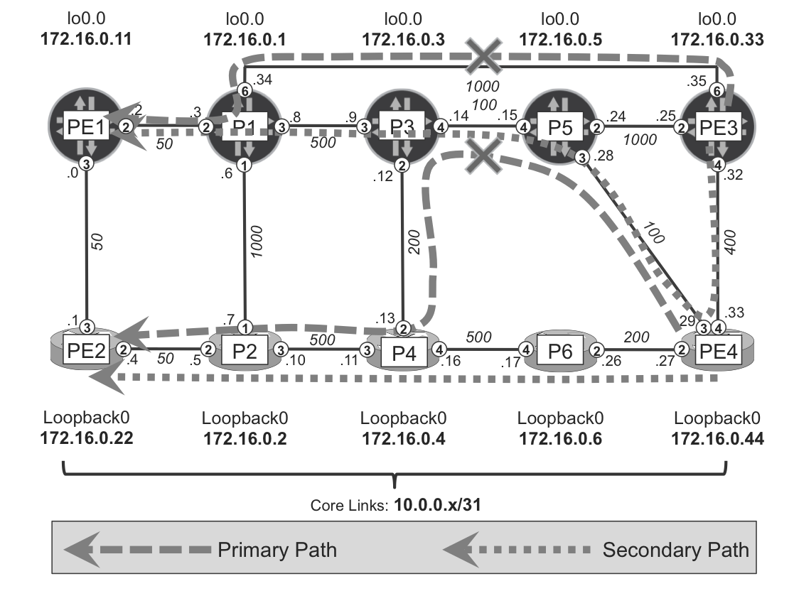
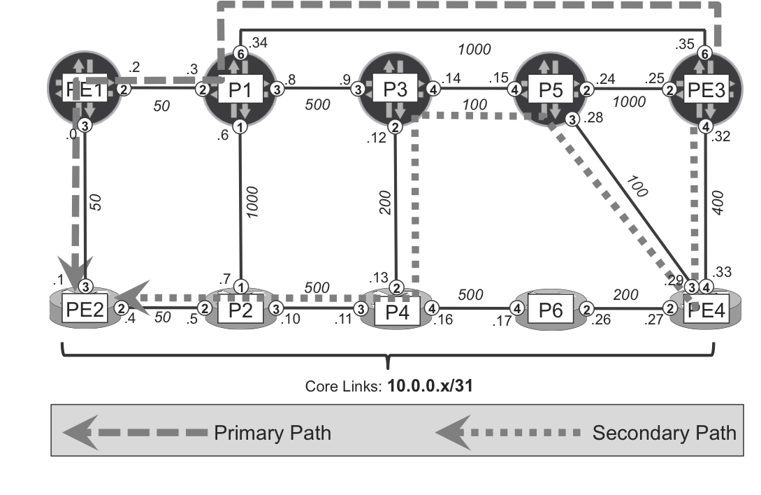
The concept of path protection is very simple: for each RSVP LSP that requires path protection, an operator defines two (or more) paths. During normal conditions, the primary path is used to forward the traffic for any given LSP. If some failure on the primary path happens, the head-end router can switch the traffic to the secondary path, as illustrated in Figure 19-1.
You can see that the LSP from PE3 to PE1 is configured with two path options. The primary path uses the PE3→P1→PE1 route, whereas the secondary path uses the PE3→PE4→P5→P3→P1→PE1 route. A simple configuration to achieve these desired results is presented Example 19-1.
Figure 19-1. RSVP path protection concepts
Example 19-1. RSVP multiple path configuration on PE3 (Junos)
The appropriate RIB entries are installed and traffic uses the primary path.
Example 19-2. Primary path forwarding verification on PE3 (Junos)
juniper@PE3> show mpls lsp name PE3--->PE1 detail | match <pattern>
From: 172.16.0.33, State: Up, ActiveRoute: 0, LSPname: PE3--->PE1
ActivePath: PE3-P1-PE1 (primary)
*Primary PE3-P1-PE1 State: UpSecondary PE3-PE4-P5-P3-P1-PE1 State: Dn
juniper@PE3> show route table inet.3 172.16.0.11/32
(...)
172.16.0.11/32 *[RSVP/7/1] 00:07:24, metric 1050
> to 10.0.0.34 via ge-2/0/6.0,
label-switched-path PE3--->PE1
juniper@PE3> traceroute mpls rsvp PE3--->PE1 | match RSVP-TE
ttl Label Protocol Address Previous Hop Probe Status
1 303440 RSVP-TE 10.0.0.34 (null) Success
2 3 RSVP-TE 10.0.0.2 10.0.0.34 Egress
Now, as Example 19-3 shows, when a failure occurs (e.g., the link between P1 and PE3 fails), the secondary path is signaled by RSVP, and the new next hop is subsequently used.
Example 19-3. Secondary path forwarding verification on PE3 (Junos)
juniper@PE3> show mpls lsp name PE3--->PE1 detail | match <pattern>
From: 172.16.0.33, State: Up, ActiveRoute: 0, LSPname: PE3--->PE1
ActivePath: PE3-PE4-P5-P3-P1-PE1 (secondary)
Primary PE3-P1-PE1 State: Dn*Secondary PE3-PE4-P5-P3-P1-PE1 State: Up
juniper@PE3> show route table inet.3 172.16.0.11/32
(...)
172.16.0.11/32 *[RSVP/7/1] 00:02:22, metric 1150
> to 10.0.0.33 via ge-2/0/4.0,
label-switched-path PE3--->PE1
juniper@PE3> traceroute mpls rsvp PE3--->PE1 | except "FEC|Hop"
ttl Label Protocol Address Previous Hop Probe Status
1 24032 RSVP-TE 10.0.0.33 (null) Success
2 301168 Unknown 10.0.0.28 10.0.0.33 Non-compliant
3 172.16.0.3 10.0.0.28 Non-compliant
4 172.16.0.1 172.16.0.3 Non-compliant
5 172.16.0.11 172.16.0.1 Egress
As of this writing, some level of interoperability inconsistency between Junos and IOS XR could be observed in MPLS RSVP-TE LSP Ping (RFC 4379 and RFC 6424). You can see the manifestation of this problem in Label (missing), Protocol (missing or Unknown) and Probe Status (Non-compliant) output fields. Because this issue didn’t cause any disturbance to the traffic itself, we didn’t dwell on it for a detailed analysis of the problem.
For the sake of completeness, let’s configure multiple paths for a RSVP-TE tunnel initiated on an IOS XR device. In this example, we configure an RVSP-TE LSP from PE4 to PE2.
Example 19-4. RSVP multiple path configuration on PE4 (IOS XR)
explicit-path name PE4-P6-P4-P2-PE2
 index 10 next-address strict ipv4 unicast 10.0.0.26
 index 20 next-address strict ipv4 unicast 10.0.0.16
 index 30 next-address strict ipv4 unicast 10.0.0.10
 index 40 next-address strict ipv4 unicast 10.0.0.4
!
explicit-path name PE4-P5-P3-P4-P2-PE2
 index 10 next-address strict ipv4 unicast 10.0.0.28
 index 20 next-address strict ipv4 unicast 10.0.0.14
 index 30 next-address strict ipv4 unicast 10.0.0.13
 index 40 next-address strict ipv4 unicast 10.0.0.10
 index 50 next-address strict ipv4 unicast 10.0.0.4
!
interface tunnel-te22
 apply-group GR-LSP
 signalled-name PE4--->PE2
 destination 172.16.0.22
 path-option 1 explicit name PE4-P5-P3-P4-P2-PE2
 path-option 2 explicit name PE4-P6-P4-P2-PE2
Based on this configuration, an LSP using the primary path is established and appropriate entries are populated. As is discussed in Chapter 2, the IGP metric for destinations reachable via RSVP-TE tunnels equals the cost of the shortest hop-by-hop path to the destination (in this example, PE4→P5→P3→P1→PE1→PE2; cost: 800). Because this shortest path is not always equal to the path taken by LSP, the reported metric values (line 7, versus 13 and 15 in Example 19-5) might differ. This is true for both Junos and IOS XR devices (with nuances described in the final sections of Chapter 3).
Example 19-5. Primary path forwarding verification on PE4 (IOS XR)
1     RP/0/0/CPU0:PE4#show mpls traffic-eng tunnels destination 172.16.0.22
2                     role head detail | include <pattern>
3     Name: tunnel-te22  Destination: 172.16.0.22  Ifhandle:0x1080
4       Signalled-Name: PE4--->PE2
5         Admin:    up Oper:   up   Path:  valid   Signalling: connected
6         path option 1,  type explicit PE4-P5-P3-P4-P2-PE2
7                                       (Basis for Setup, path weight 950)
8         path option 2,  type explicit PE4-P6-P4-P2-PE2
9         Outgoing Interface: Gi0/0/0/3, Outgoing Label: 301360
10
11    RP/0/0/CPU0:PE4#show route 172.16.0.22/32
12    (...)
13      Known via "isis core", distance 115, metric 800, type level-2
14        172.16.0.22, from 172.16.0.22, via tunnel-te22
15          Route metric is 800
16
17    RP/0/0/CPU0:PE4#traceroute mpls traffic-eng tunnel-te 22
18    (...)
19      0 10.0.0.29 MRU 1500 [Labels: 301584 Exp: 0]
20    L 1 172.16.0.5 MRU 1514 [Labels: 302448 Exp: 7] 30 ms
21    L 2 172.16.0.3 MRU 1514 [Labels: 24010 Exp: 7] 220 ms
22    L 3 10.0.0.13 MRU 1500 [Labels: 24011 Exp: 0] 10 ms
23    L 4 10.0.0.10 MRU 1500 [Labels: implicit-null Exp: 0] 10 ms
24    ! 5 10.0.0.4 10 ms
The trace output is as expected. There are some differences, however, in the reported addresses (loopbacks versus link addresses) or Maximum Receive Unit (MRU) sizes (including or excluding the Layer 2 header) depending on whether the reporting node is Junos or IOS XR.
After a network failure occurs (e.g., on the P3-P5 link) traffic shifts to the secondary path, as demonstrated in Example 19-6. This time, the LSP metric (line 7) and the IGP metric (lines 13 and 15) are equal, because after failure of the P3-P5 link, the shortest path to the destination equals the secondary path.
Example 19-6. Secondary path forwarding verification on PE4 (IOS XR)
1     RP/0/0/CPU0:PE4#show mpls traffic-eng tunnels destination 172.16.0.22
2                     role head detail | include <pattern>
3     Name: tunnel-te22  Destination: 172.16.0.22  Ifhandle:0x480
4       Signalled-Name: PE4--->PE2
5         Admin:    up Oper:   up   Path:  valid   Signalling: connected
6         path option 2,  type explicit PE4-P6-P4-P2-PE2 (Basis for Setup,
7                         path weight 1250)
8         path option 1,  type explicit PE4-P5-P3-P4-P2-PE2
9         Outgoing Interface: Gi0/0/0/2, Outgoing Label: 24012
10
11    RP/0/0/CPU0:PE4#show route 172.16.0.22/32
12    (...)
13      Known via "isis core", distance 115, metric 1250, type level-2
14        172.16.0.22, from 172.16.0.22, via tunnel-te22
15          Route metric is 1250
16
17    RP/0/0/CPU0:PE4#traceroute mpls traffic-eng tunnel-te 22
18    (...)
19      0 10.0.0.27 MRU 1500 [Labels: 24012 Exp: 0]
20    L 1 10.0.0.26 MRU 1500 [Labels: 24010 Exp: 0] 10 ms
21    L 2 10.0.0.16 MRU 1500 [Labels: 24011 Exp: 0] 10 ms
22    L 3 10.0.0.10 MRU 1500 [Labels: implicit-null Exp: 0] 0 ms
23    ! 4 10.0.0.4 10 ms
So far, so good. But what traffic restoration times could you imagine in your design? When a failure happens, the following sequence of events are executed:
Failure detection
The secondary path is signaled via RSVP-TE
Installation of a new next hop in the RIB/FIB structures
If the failure occurs close to the head-end router (e.g., the PE3-P1 link fails on the primary path used by LSP from PE3 to PE1), failure detection can be rather quick. Failure of directly connected links or neighbors can be discovered rapidly.
If the failure is farther away from the head-end router (e.g., the P3-P4 link fails on the primary path used by LSP from PE4 to PE2), information about the failure can be propagated to the head-end or tail-end routers (PE4 or PE2) via RSVP-TE signaling messages (PathErr, ResvTear) generated by the router that detects the failure. Alternatively, after IGP global convergence, all the routers in the domain (including head-end and tail-end routers) gain knowledge about the failed link or node. This failure detection can be quite long (several hundred milliseconds), and for certain applications, too long. This problem is discussed a little later in this chapter.
For now, let’s check the second and third element of the overall time required for traffic restoration. When a network failure affects the primary path, a secondary path must be signaled and a new next hop installed in RIB/FIB. This certainly takes time, especially in scaled environments with large numbers of LSPs. Therefore you can use the same trick as discussed in the Loop-Free Alternates (LFA) scenarios: preinstalling backup next hops.
Obviously, to preinstall a backup next hop, the secondary path must be presignaled. So, let’s do that. You simply designate the secondary path as a standby path, as shown in Example 19-7. A standby path is presignaled and corresponds to the next hop preinstalled in the RIB/FIB. But it is only a backup next hop—just like in the LFA case.
Example 19-7. RSVP-TE secondary standby path configuration—PE3 (Junos)
Now let’s check what’s the difference in the various states related to the PE3--->PE1 LSP.
Example 19-8. Primary/standby path states on PE3 (Junos)
juniper@PE3> show mpls lsp name PE3--->PE1 detail | match <pattern>
From: 172.16.0.33, State: Up, ActiveRoute: 0, LSPname: PE3--->PE1
ActivePath: PE3-P1-PE1 (primary)
*Primary PE3-P1-PE1 State: UpStandby PE3-PE4-P5-P3-P1-PE1 State: Up
juniper@PE3> show route table inet.3 172.16.0.11/32 detail | match ...
*RSVP Preference: 7/1
Next hop: 10.0.0.34 via ge-2/0/6.0 weight 0x1, selected
Label-switched-path PE3--->PE1
Next hop: 10.0.0.33 via ge-2/0/4.0 weight 0x2001
Label-switched-path PE3--->PE1
Age: 23:15 Metric: 1050
You can see the secondary path is presignaled (state is up) and the backup next hop is preinstalled. This time, though, the weight for the backup next hop is 0x2001 (in the LFA case, it was 0xf000, 0x100, or 0x8000, depending on the LFA style used). As long as it is greater than 0x1, it is a backup next hop.
Let’s also do the same on the IOS XR device, as shown in Example 19-9. Enabling the path-protection feature and designating one of the path options (e.g., path option 2) to protect the primary path (path option 1) causes the protecting path (path option 2) to be presignaled.
Example 19-9. Primary/standby path configuration and states—PE4 (IOS XR)
interface tunnel-te22
path-protection
path-option 1 explicit name PE4-P5-P3-P4-P2-PE2 protected-by 2
path-option 2 explicit name PE4-P6-P4-P2-PE2
RP/0/0/CPU0:PE4#show mpls traffic-eng tunnels destination 172.16.0.22role head detail | include <pattern>
Name: tunnel-te22 Destination: 172.16.0.22 Ifhandle:0x480
Signalled-Name: PE4--->PE2
Admin: up Oper: up Path: valid Signalling: connected
path option 1, type explicit PE4-P5-P3-P4-P2-PE2
(Basis for Setup, path weight 950)
path option 2, type explicit PE4-P6-P4-P2-PE2
(Basis for Standby, path weight 1250)
Standby Path: User defined [explicit path option: 2],
Outgoing Interface: Gi0/0/0/3, Outgoing Label: 301360
Outgoing Interface: Gi0/0/0/2, Outgoing Label: 24012
Manually designing and explicitly configuring primary and secondary path options might be a challenging task, especially in large networks. Furthermore, as your network changes during its lifetime (typically networks grow and sometimes network topologies are modified), keeping track of the most optimal primary and secondary paths could become an operational nightmare. To cope, you can establish primary and secondary paths dynamically.
In typical designs, the primary path is restricted to use only certain links (e.g., links with the smallest delay)—the required techniques for this are discussed in Chapters Chapter 13 and Chapter 15, so they are not covered here.
Let’s simply configure two dynamic paths—primary and secondary—without any explicit constraints.
Example 19-10. Dynamic primary/secondary standby path—PE3 (Junos)
Lines 10 and 11 demonstrate how you can define path options without specifying any next hops. They are basically empty path options. These path options become populated with explicit lists of next hops by a constrained SPF algorithm during the LSP creation time. (This is discussed in Chapter 2.) But what is new here is the way in which these paths are calculated by CSPF.
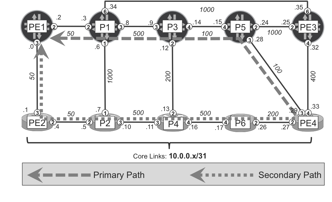
First, the path options that are designated as primary, named PRIMARY in the example, follow standard CSPF rules, which in the end produce paths based on the lowest total cost to the destination (because no constraints are imposed on the primary path in the example). This cost is 1100, as shown in Figure 19-2 and in Example 19-11, line 5.
Example 19-11. States for primary/standby paths on PE3 (Junos)
1     juniper@PE3> show mpls lsp name PE3--->PE2 detail | match <pattern>
2      From: 172.16.0.33, State: Up, ActiveRoute: 0, LSPname: PE3--->PE2
3      ActivePath: PRIMARY (primary)
4     *Primary   PRIMARY          State: Up
5       Computed ERO (S [L] denotes strict [loose]): (CSPF metric: 1100)
6      10.0.0.34 S 10.0.0.2 S 10.0.0.1 S
7      Standby   SECONDARY        State: Up
8       Computed ERO (S [L] denotes strict [loose]): (CSPF metric: 1350)
9      10.0.0.33 S 10.0.0.28 S 10.0.0.14 S 10.0.0.13 S 10.0.0.10 S
10     10.0.0.4 S
Conversely, the path option designated as secondary standby (called SECONDARY in the example) is calculated using different rules. You can discover those rules by enabling and monitoring logs for CSPF events, as shown in Example 19-12, and Example 19-13, respectively.
Example 19-12. Enabling logs for CSPF events on PE3 (Junos)
protocols {
    mpls {
        traceoptions {
            file cspf size 100m;
            flag cspf;
            flag cspf-link;
            flag cspf-node;
}}}
Example 19-13. Monitoring logs for CSPF events on PE3 (Junos)
1     juniper@PE3> monitor start cspf
2     (...)
3     <timestamp> CSPF for path PE3--->PE2(secondary SECONDARY)
4     <timestamp> CSPF final destination 172.16.0.22
5     <timestamp> CSPF starting from PE3.00 (172.16.0.33) to 172.16.0.22
6     <timestamp> constraint avoid primary path
7     <timestamp> Node PE3.00 (172.16.0.33) metric 0, hops 0,
8                 avail 32000 32000 32000 32000
9     <timestamp>   Link 10.0.0.35->10.0.0.34(P1.00/172.16.0.1,
10          Link IDs 338->335) metric 1000 color 0x0 bw 900Mbps
11    <timestamp> link passes constraints
12    <timestamp> Link overlap with primary path, adding cost 8000000
13    (...)
When checking the logs, you can spot an entry that indicates the start of CSPF for the secondary path (line 3). CSPF for the secondary path tries to avoid the primary path (line 6), so that the primary and secondary paths are distinct to the highest possible degree. Recall from the discussion about MRTs in Chapter 18, the logic was similar: MRT-red and MRT-blue forwarding topologies should be distinct, whenever possible. Now, the primary and secondary paths should be diverse, to the highest possible degree. Whereas MRT uses a sophisticated algorithm to find dissimilar paths for MRT-red and MRT-blue forwarding, Junos CSPF for the secondary path uses a more basic approach, as visible in line 12. Put simply, the cost of links used by the primary path is temporarily increased by 8 million. Thus, in this particular example, link PE3→P1 (line 9) is considered by CSPF with a total cost of 8001000: IGP metric 1000 (line 10) + extra cost 8 million (line 12). In this way, CSPF temporarily increases the cost for all the links used by the primary path.
You can see the results of the primary and secondary path computation in Figure 19-2, and in Example 19-11 (line 6 for primary, lines 9 and 10 for secondary). The primary is a path with the smallest total cost (PE3→P1→PE1→PE2; total cost: 1100), whereas the secondary is a completely distinct path (PE4→P5→P3→P4→P2→PE2; total cost: 1350). There are no common links between primary and secondary paths. Also note that the secondary path is not the second shortest path after the primary. The second shortest path in the example topology is PE3→PE4→P5→P3→P1→PE1→PE2, with a total cost of 1200. This path is not chosen for a secondary path option, though, because it shares some links (P1→PE1→PE2) with the primary path. As you can see, the default algorithm to calculate paths for dynamic primary and secondary options provides very good results.
The results with IOS XR are similar. If path-protection is configured, you can simply define one dynamic path option. The second dynamic path (to protect the first one) will be automatically presignaled.
Example 19-14. Dynamic primary/secondary standby path—PE4 (IOS XR)
Figure 19-3 and Example 19-15 show the path computations. There is, however, a slight difference between Junos and IOS XR behavior when it comes to calculating paths for secondary path options. Junos tries to avoid the links used by the primary path by increasing, temporarily, metrics for these links. It might happen, however, that the secondary path shares some links with the primary path. IOS XR, on the other hand, completely avoids such links (and nodes) by temporarily removing these links (nodes) from the database used as the input for CSPF calculations (see line 7 in Example 19-15). Thus, in IOS XR, the secondary path must be completely distinct from the primary path. If such a path cannot be found, the secondary path is not presignaled.
Example 19-15. States for primary/standby paths on PE4 (IOS XR)
The last thing you should know about path protection is how RSVP-TE signals different paths belonging to same RSVP-TE tunnel. If you carefully study Chapter 2 and RFC 3209 (RSVP-TE: Extensions to RSVP for LSP Tunnels), RSVP-TE maintains a couple of IDs used for identification of tunnels and paths:
Tunnel ID
A 16-bit identifier used in the SESSION that remains constant over the life of the tunnel.
LSP ID
A 16-bit identifier used in the SENDER_TEMPLATE and the FILTER_SPEC that can be changed to allow a sender to share resources with itself.
In Junos, you can easily monitor RSVP-TE packet exchange by capturing packets with IP protocol 46 (this is the IP protocol ID assigned to RSVP). If you sniff packets on different interfaces (with Junos command monitor traffic interface <int> size 2000 no-resolve detail), you can catch RSVP packets handling primary as well as secondary paths of PE3--->PE2, as shown in Example 19-16.
Example 19-16. RVSP packets monitoring on PE3 (Junos)
The tunnel ID is the same for all paths of the same RSVP-TE tunnel. It is manually assigned in IOS XR (the same as the configured interface tunnel ID) and automatically assigned in Junos. You can see that Tunnel ID 0xb14d (45389 in decimal) is used in the RSVP-TE signaling messages by both the primary (line 5) and the secondary (line 18) paths. The LSP ID, however, is different on both paths. The primary uses 0x0037 (line 12), whereas the secondary uses 0x0038 (line 25). Each time the path is changed (e.g., due to reoptimization) or a new path added, the new LSP ID is automatically generated, maintaining multiple paths belonging to the same RSVP-TE tunnel.
RSVP-TE Facility (Node-Link) Protection
Path protection is based on switchover between the primary and secondary standby paths. The head-end router performs this switchover, so failure information must first be propagated to the head-end router before any repair action can be executed. If the failure happens close to the head-end router (failure of a directly connected link or a directly connected node), failure detection is quite quick. If, however, failure happens farther away from the head-end router, the following failure detection methods can trigger path switchover:
Notification from the IGP that the topology has changed (e.g., some of the transit routers are no longer available)
RSVP PathErr or ResvTear messages
Notification from the Bidirectional Forwarding Detection (BFD) protocol running as the LSP’s OAM, which indicates that forwarding over the LSP is broken
Any of these events can result in a relatively slow failure detection, and thus path switchover might by triggered relatively late after failure occurs. For certain loss-sensitive applications this is undesirable.
Thus, RFC 4090 (Fast Reroute Extensions to RSVP-TE for LSP Tunnels) introduces two options for protecting traffic flowing via RSVP-TE tunnels using the local-repair paradigm. Similar to the protection cases available for LDP and SPRING (different variants of LFA), traffic is repaired locally; thus, the failure propagation time to head-end router no longer plays a significant role.
Because the terminology used for these two options across vendors can become a bit confusing, Table 19-1 summarizes the terms used by Junos and IOS XR as well as by the RFC (this book uses the RFC terms in all further discussions.)
Table 19-1. RSVP-TE protection terminology
RFC 4090
One-to-one backup
Facility backup
Junos
Fast ReRoute
Link Protection
Node-Link Protection
IOS XR
n/a
Fast ReRoute Protection Any
Fast ReRoute Protection Node
One of the two options described in RFC 4090 is facility backup, whereby “facility” is defined as a link or node. This option shows some similarities to per-link LFA discussed earlier in this chapter. Namely, with facility backup, all eligible traffic flowing through the protected facility (link or node) is rerouted by the means of local repair over the same backup next hop when the facility (link or node) fails.
The problem with per-link LFA is its high dependency on topology, which results in no loop-free backup next hop in many situations. This limitation does not affect RSVP-TE protection. Because RSVP-TE has the capability to signal explicit paths, after the path is signaled and states are created on all transit routers, packets do not necessarily use the shortest-path for forwarding any longer. Explicit path specification creates the opportunity to presignal any bypass path, which is completely independent from the network topology or IGP metrics. You used this capability of RSVP-TE in Chapter 18, when you extended LFA backup coverage with manual or dynamic RSVP-TE tunnels. This chapter focuses on pure RSVP-TE scenarios.
So, let’s do it. But before getting under way with this section, you must set all RSVP-TE tunnels (full mesh between PE routers) back to their basic state (single, dynamic path option per tunnel.) Then, taking this book’s topology as a reference, this is the path followed by each right-to-left tunnels:
PE3--->PE1 tunnel: PE3→P1→PE1
PE3--->PE2 tunnel: PE3→PE4→P5→P3→P4→P2→PE2
PE4--->PE1 tunnel: PE4→P5→P3→P1→PE1
PE4--->PE2 tunnel: PE4→P5→P3→P4→P2→PE2
Remember that in the IGP and TE worlds, links are seen as two half-links. Let’s focus on P5→P3, whose reverse half-link is P3→P5. According to the previous list, the following three LSPs transit the (half-)link P5→P3: PE3--->PE2, PE4--->PE1, and PE4--->PE2.
Manual Link Protection Bypass
Manual bypass LSPs are configured with a strict hop-by-hop ERO. The process is tedious but it provides more control. Automatic bypass LSPs are discussed later in this chapter.
Manual link protection bypass in Junos: P5→P3 link, PE4--->PE2 LSP
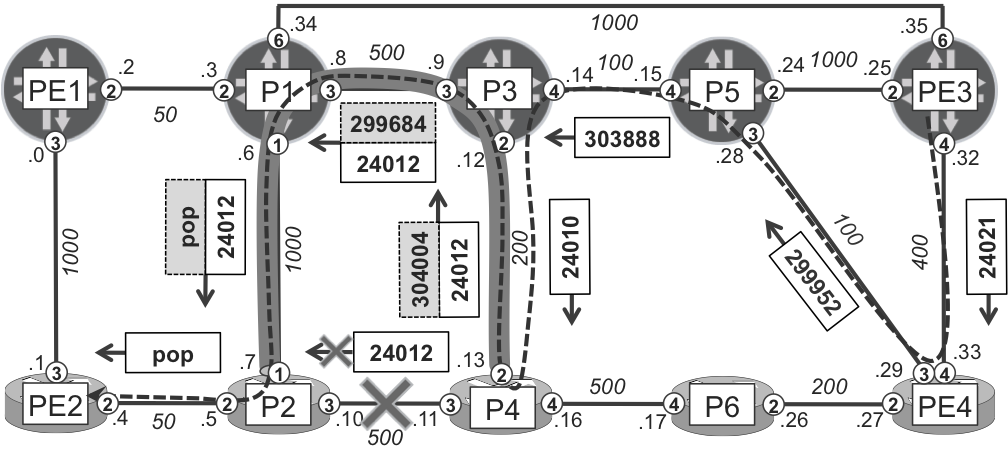
Figure 19-4 illustrates a manual bypass LSP, which protects the P5→P3 link. The figure also depicts how this bypass LSP protects the PE4--->PE2 LSP in case of link failure.
In the absence of failures, the PE4--->PE2 LSP follows the original path, represented in Figure 19-4 with white labels. The bypass LSP (gray labels on top of the white labels) are used only during local repair after a P5→P3 link failure.
Note
The PE4--->PE1 LSP, which also transits the P5→P3 link, would be protected by the same bypass LSP. Using the color code in Figure 19-4, the PE4--->PE1 LSP would have different white labels, but the same gray labels for P5→P3 local repair. This is an essential property of facility protection: all the protected LSPs transiting a protected resource rely on the same bypass LSP.
Example 19-17. Manual link protection bypass LSP on P5 (Junos)
1     protocols {
2         rsvp {
3             interface ge-2/0/4.0 {
4                 link-protection {
5                     bypass P5-PE3-P1-P3 {
6                         to 172.16.0.3;
7                         bandwidth 0;
8                         path {
9                             10.0.0.25 strict;
10                            10.0.0.34 strict;
11                            10.0.0.9 strict;
12    }}}}}}
13
14    juniper@P5> show rsvp interface ge-2/0/[234].0 extensive | match ...
15    ge-2/0/2.0 Index 333, State Ena/Up
16      Authentication, Aggregate, Reliable, NoLinkProtection
17      Protection: Off
18    ge-2/0/3.0 Index 334, State Ena/Up
19      Authentication, Aggregate, Reliable, NoLinkProtection
20      Protection: Off
21    ge-2/0/4.0 Index 335, State Ena/Up
22      Authentication, Aggregate, Reliable, LinkProtection
23      Protection: On, Bypass: 0, LSP: 0, Protected LSP: 0,
24                                         Unprotected LSP: 0
A quick verification shows that out of three interfaces for which RSVP is enabled, only one has protection switched on. This is in line with the configuration just committed. However, you also can see in line 23 that no bypass LSP is created and no LSP is currently protected. This is unfortunate, because it means that the efforts are ineffective at the moment.
The problem is that all traffic is considered as not eligible for protection by default in RSVP-TE. This is just the opposite of LFA, for which by default all traffic is eligible for protection and the system tries to install the backup next hop for as many prefixes/labels as possible. In RSVP-TE, you need to explicitly designate the traffic that requires protection. Let’s do it initially for the traffic flowing over PE4--->PE2 and PE3--->PE2 tunnels, following the syntax shown here:
Example 19-18. Local Protection request for PE4--->PE2 on PE4 (IOS XR)
interface tunnel-te22
 fast-reroute
Example 19-19. Local Protection request for PE3--->PE2 LSP on PE3 (Junos)
As illustrated in Example 19-20, the protection states on P5 (it might take some time initially) now look much better.
Example 19-20. Facility (link) protection state on P5 (Junos)
1     juniper@P5> show rsvp interface ge-2/0/4.0 extensive | find ...
2     Protection: On, Bypass: 1, LSP: 2, Protected LSP: 2,
3                 Unprotected LSP: 0
4         1 Feb  5 21:36:29 New bypass P5-PE3-P1-P3
5       Bypass: P5-PE3-P1-P3, State: Up, Type: LP, LSP: 1, Backup: 0
6         3 Feb  5 21:36:31 Record Route:  10.0.0.25 10.0.0.34 10.0.0.9
7         2 Feb  5 21:36:31 Up
8         1 Feb  5 21:36:30 CSPF: computation result accepted
You can see that bypass LSP is now established. This bypass type (line 5) is LP (link protection), and currently only two regular LSPs can use this bypass for protection (just before, you requested protection for PE4--->PE2 and PE3--->PE2 tunnels only.) You can verify the status of regular LSPs transiting P5 node, as well.
Example 19-21. Protection state of transit LSPs on P5 (Junos)
juniper@P5> show mpls lsp detail | match "name|protect"
LSPname: PE4--->PE1
LSPname: PE4--->PE2
Link protection desiredType: Link protected LSP
LSPname: PE3--->PE2, LSPpath: Primary
Link protection desiredType: Link protected LSP
LSPname: PE2--->PE3
LSPname: PE2--->PE4
LSPname: PE1--->PE4, LSPpath: Primary
After configuring IOS XR fast-reroute option (Example 19-18) for the PE4--->PE2 LSP or Junos link-protection option (Example 19-19) for the PE3--->PE2 LSP, these LSPs are signaled using special flags in the RSVP-TE Session Attribute Object.
Note
Make a copy of Figure 19-4 and keep it handy throughout this explanation.
Adding the hidden (and unsupported) knob write-file to the packet capturing command from Example 19-16, this time on P5’s ge-2/0/3 interface, you can save the RSVP packets into a file for further analysis by external tools (like Wireshark or TShark). This gives you the option of inspecting RSVP packets in detail, including the aforementioned flags. Let’s see a Path message for the PE4--->PE2 LSP (Example 19-22).
Example 19-22. Collected RVSP packets decoding using TShark
1     [linux:~/Downloads] juniper% tshark -r rsvp-path-lp.pcap -V
2     (...)
3     Resource ReserVation Protocol (RSVP): PATH Message. SESSION:
4       IPv4-LSP, Destination 172.16.0.22, Short Call ID 0, Tunnel ID 22,
5       Ext ID ac10002c. SENDER TEMPLATE: IPv4-LSP, Tunnel Source:
6       172.16.0.44, Short Call ID: 0, LSP ID: 53.
7     (...)
8         SESSION ATTRIBUTE: SetupPrio 7, HoldPrio 7, Local Protection,
9                            Label Recording, SE Style,  [PE4--->PE2]
10    (...)
11                Flags: 0x07
12                    .... ...1 = Local protection: Desired
13                    .... ..1. = Label recording: Desired
14                    .... .1.. = SE style: Desired
15                    .... 0... = Bandwidth protection: Not Desired
16                    ...0 .... = Node protection: Not Desired
PE4 requests local protection for the PE4--->PE2 tunnel (line 12). PE4 requests neither bandwidth nor node protection (lines 15-16), which means the bypass tunnel does not need to satisfy those protection criteria.
Now let’s review how the protection is actually achieved.
Example 19-23. Status of PE4--->PE2 RSVP-TE tunnel on PE4 (IOS XR)
1     RP/0/0/CPU0:PE4#show mpls traffic-eng tunnels 22 detail
2     [...]
3     Outgoing Interface: GigabitEthernet0/0/0/3, Outgoing Label: 299920
4       Resv Info:
5         Record Route:
6           IPv4 172.16.0.5, flags 0x21 (Node-ID, Protection: available)
7           IPv4 10.0.0.28, flags 0x1 (Protection: available)
8           Label 299920, flags 0x1
9           IPv4 172.16.0.3, flags 0x20 (Node-ID)
10          IPv4 10.0.0.14, flags 0x0
11          Label 306128, flags 0x1
12          IPv4 172.16.0.4, flags 0x20 (Node-ID)
13          Label 24023, flags 0x1
14          IPv4 10.0.0.13, flags 0x0
15          Label 24023, flags 0x1
16          IPv4 172.16.0.2, flags 0x20 (Node-ID)
17          Label 24011, flags 0x1
18          IPv4 10.0.0.10, flags 0x0
19          Label 24011, flags 0x1
20          IPv4 172.16.0.22, flags 0x20 (Node-ID)
21          Label 3, flags 0x1
22          IPv4 10.0.0.4, flags 0x0
23          Label 3, flags 0x1
24
25    [linux:~/Downloads] juniper% tshark -r rsvp-resv-lp.pcap -V
26      Resource ReserVation Protocol (RSVP): RESV Message [...]
27    [...]
28      RECORD ROUTE: IPv4 172.16.0.5 (Node-id), IPv4 10.0.0.28,
29       Label 299920,  (Node-id)... (Node-id) (Node-id) (Node-id)
30        Length: 148
31        Object class: RECORD ROUTE object (21)
32        C-type: 1
33        IPv4 Subobject - 172.16.0.5 (Node-id), Local Protection Avail.
34            Type: 1 (IPv4)
35            Length: 8
36            IPv4 hop: 172.16.0.5 (172.16.0.5)
37            Prefix length: 32
38            Flags: 0x21
39                .... ...1 = Local Protection: Available
40                .... ..0. = Local Protection: Not used
41                .... .0.. = Bandwidth Protection: Not available
42                .... 0... = Node Protection: Not available
43                ..1. .... = Address Specifies a Node-id Address: Yes
44        IPv4 Subobject - 10.0.0.28, Local Protection Available
45            Type: 1 (IPv4)
46            Length: 8
47            IPv4 hop: 10.0.0.28 (10.0.0.28)
48            Prefix length: 32
49            Flags: 0x01
50                .... ...1 = Local Protection: Available
51                .... ..0. = Local Protection: Not used
52                .... .0.. = Bandwidth Protection: Not available
53                .... 0... = Node Protection: Not available
54                ..0. .... = Address Specifies a Node-id Address: No
55        Label Subobject - 299920, The label will be understood if
56                                  received on any interface
57     [...]
P5 can act as a PLR for the PE4--->PE2 LSP by providing the requested protection, downstream from its position in the tunnel. For this reason, P5 sets the “Local protection: Available” flag on the two RRO entries that it adds to the Resv message. By looking at these flags, PE4 knows that P5 is able to provide local protection in case failure downstream happens. On the other hand, flag “Local protection: Use” is not set. Therefore, local protection is currently not active.
Note
It is essential for the head-end PE to be informed of the protection available and active at each of the transit nodes. Otherwise, it would tear down the LSP immediately upon failure detection.
At first glance, it might look strange that some protection capability for the 10.0.0.28 address (address from PE4-P5 link) is being reported. Did you configure any protection for this link? No. So far only the simple bypass LSP to protect the P5→P3 link has been configured. But if you carefully read RFC 4090, Section 4.4, you will note that this protection flag indicates that the link downstream of this node is protected via a local-repair mechanism. Therefore, it’s not that the PE4-P5 link (to which IP address 10.0.0.28 belongs) is protected, but the link downstream of the node with the 10.0.0.28 address is. In essence, we’re talking about the link downstream of the P5 node, which is P5→P3.
OK, so what happens on P5? Let’s check that.
Example 19-24. MPLS RIB entry on P5 (Junos)
1     juniper@P5> show route label 299920 detail | match "Pref|via|Label"
2       *RSVP   Preference: 7/1
3               Next hop: 10.0.0.14 via ge-2/0/4.0 weight 0x1, selected
4               Label-switched-path PE4--->PE2
5               Label operation: Swap 306128
6               Next hop: 10.0.0.25 via ge-2/0/2.0 weight 0x8001
7               Label-switched-path P5-PE3-P1-P3
8               Label operation: Swap 306128, Push 299856(top)
There are two next hops with different weights. It’s similar to the protection cases we discussed previously. The first next hop is the standard one used for normal label switching along the PE4--->PE2 tunnel. You can compare label 306128 (line 5 in the previous example) with the label shown in line 11 of Example 19-23. Looks similar? The second next hop, as the weight indicates, is the backup next hop. When P5 sends a packet over the backup next hop, it uses two labels (line 8): the normal label for PE4--->PE2 tunnel (306128, the same as in line 5), and the additional top label 299856. What is this label? Check Figure 19-4 and Example 19-25.
Example 19-25. State for bypass LSP on P5 (Junos)
juniper@P5> show rsvp session ingress
To          From        State Rt Style Labelin Labelout LSPname
172.16.0.3  172.16.0.5  Up    0  1 SE       -   299856 P5-PE3-P1-P3
Note
In Junos, ingress (head-end) bypass LSPs are not visible when you use the show mpls lsp command. To display information about ingress (head-end) bypass LSPs, you need to use the show rsvp session command.
This is, in fact, the label for the bypass LSP created previously! So your regular LSP is tunneled inside the bypass LSP in case of P5→P3 link failure. The last segment (P1→P3) of the bypass LSP uses the implicit null label, meaning the traffic will arrive at P3 with the label from the regular LSP (306128). Does the fact that packet arrives at P3 on the wrong interface cause any problem (ge-2/0/3.0 instead of ge-2/0/4.0, which is on the path for the regular PE4--->PE1 LSP)? If you look again at lines 8, 11, 13, and 17 of Example 19-23, you will find that all labels on the path are advertised with flag 0x1. What does it mean? Again, lines 55 and 56 of Example 19-23 provide the answer: the label has global (per-node, not per-interface) significance, so packets with this label are properly forwarded regardless of the interface on which they are received. Perfect, you are now set.
If you check more entries in the MPLS RIB, such as in the next example, you can see that out of three tunnels transiting the P5→P3 link, only two tunnels are protected (have a backup next hop). These tunnels are PE3--->PE2 and PE4--->PE2. The PE4--->PE1 tunnel was not configured to request protection, so it is not protected.
Note
Remember that in RSVP-TE, protection needs to be explicitly requested on a per-tunnel basis.
Example 19-26. MPLS RIB on P5 (Junos)
1     juniper@P5> show route table mpls.0 | find RSVP
2     299920 *[RSVP/7/1] 00:34:52, metric 1
3         > to 10.0.0.14 via ge-2/0/4.0, label-switched-path PE4--->PE2
4           to 10.0.0.25 via ge-2/0/2.0, label-switched-path P5-PE3-P1-P3
5     299952 *[RSVP/7/1] 00:10:33, metric 1
6         > to 10.0.0.14 via ge-2/0/4.0, label-switched-path PE3--->PE2
7           to 10.0.0.25 via ge-2/0/2.0, label-switched-path P5-PE3-P1-P3
8     300000 *[RSVP/7/1] 00:09:20, metric 1
9         > to 10.0.0.14 via ge-2/0/4.0, label-switched-path PE4--->PE1
10    (...)
Manual link protection bypass in IOS XR: P4→P2 link, PE3--->PE2 LSP
To understand the complete picture about facility protection on both Junos and IOS XR planes, let’s add a bypass LSP in the IOS XR plane (e.g., on router P4 to protect the P4→P2 link), as shown in Figure 19-5.
Example 19-29. Facility (link) protection state on P4 (IOS XR)
1     RP/0/0/CPU0:P4#show mpls traffic-eng tunnels 2 brief
2                TUNNEL NAME         DESTINATION      STATUS  STATE
3                 tunnel-te2          172.16.0.2          up  up
4
5     RP/0/0/CPU0:P4#show mpls traffic-eng tunnels role mid | match ...
6       Tunnel Name: PE4--->PE2 Tunnel Role: Mid
7           Session Attributes: Local Prot: Set, Node Prot: Not Set,
8                               BW Prot: Not Set
9       Tunnel Name: PE2--->PE3 Tunnel Role: Mid
10          Session Attributes: Local Prot: Not Set, Node Prot: Not Set,
11                              BW Prot: Not Set
12      Tunnel Name: PE2--->PE4 Tunnel Role: Mid
13          Session Attributes: Local Prot: Not Set, Node Prot: Not Set,
14                              BW Prot: Not Set
15      Tunnel Name: PE3--->PE2 Tunnel Role: Mid
16          Session Attributes: Local Prot: Set, Node Prot: Not Set,
17                              BW Prot: Not Set
18
19    RP/0/0/CPU0:P4#show mpls forwarding labels 24010 detail
20    Local  Outgoing  Prefix      Outgoing     Next Hop     Bytes
21    Label  Label     or ID       Interface                 Switched
22    ------ --------- ----------- ------------ ------------ --------
23    24010  24012     39732         Gi0/0/0/3    10.0.0.10    0
24         Path Flags: 0x400 [ BKUP-IDX:1 (0xa14d64e0) ]
25    (...)
26
27    RP/0/0/CPU0:P4#show mpls traffic-eng fast-reroute database
28    LSP midpoint FRR information:
29    LSP Identifier         Local  Out Intf/        FRR Intf/  Status
30                           Label  Label            Label
31    ---------------------- ------ ---------------- ---------- -------
32    172.16.0.33 39732 [4]  24010  Gi0/0/0/3:24012  tt2:24012  Ready
33    172.16.0.44 22 [29]    24023  Gi0/0/0/3:24012  tt2:24012  Ready
Let’s analyze Example 19-29. As you can see, the bypass tunnel is up (line 3). Two (out of four) transit (mid point) LSPs request protection, which is signaled via the appropriate flags in Session Attributes Object (lines 7 and 16). Verifying the MPLS forwarding entry (lines 19 through 24) for one of the transit tunnels (Lines 13 and 14 in Example 19-28 determine the incoming and outgoing labels at P4, which are 24010 and 24012, respectively), you can see the normal outgoing label (24012, as in line 23) as well as some reference to the backup path (line 24). You can determine this backup path by using the command in line 27, which shows protection for the PE3--->PE2 (line 32) LSP and the PE4--->PE2 LSP (line 33). Again, you can see the standard primary outgoing interface and label as well as the backup next hop interface in different columns. In essence, incoming packets with the label 24010 are forwarded over Gi0/0/0/3 and the label is swapped to 24012. Or, if this interface is not available, packets are forwarded via bypass tunnel 2 and the label swapped to 24012. Because the bypass tunnel has its own label (see the gray labels in Figure 19-5), the end result is a label stack of two labels after P4 performs swap 24012 and push 304004 (bypass label) operations.
Note
Unlike Junos, IOS XR always brings up the manual bypass tunnel, even if there is no single regular LSP that requires protection.
Manual Node-Link Protection Bypass
By now, you should be familiar with how to deploy link protection. So, let’s create additional bypass tunnels, but this time to provide protection not simply against link failure, but also against downstream node failure, as well.
So, for example, if you need a bypass tunnel from P4 to PE2 in order to protect against P2 failure, the following path (see Figure 19-6) meets the requirements: P4→P3→P1→PE1→PE2. The configuration of this bypass tunnel is similar to the one presented in Example 19-27, but the termination point is the neighbor’s neighbor (PE2); it is no longer the directly connected neighbor (P2), against whose failure we want to protect. And, of course, the explicit path must not use the node being protected (P2).
Note
Link protection bypass is often referenced as NHOP (next-hop) bypass, whereas node-link protection bypass is often referenced as NNHOP (next-next-hop) bypass.
If you carefully compare the output from Example 19-29 and Example 19-30, you will realize that the tunnel used for protection has changed. Instead of tt2 (NHOP bypass terminated on P2), tt22 (NNHOP bypass terminated on PE2) is used.
Figure 19-6 shows the resulting label operations for LSP PE3--->PE2 after P2-P4 link failure, or after P2 node failure. Actually, P4 can protect the link P2-P4 with either a NHOP bypass or a NNHOP bypass. P4 chooses the best option available (and NNHOP is superior to NHOP). When the link P2-P4 fails, P4 does not know at first whether it is a link or a node failure, so it reacts as if it had been a node failure.
Before pushing the bypass LSP label, P4 pops the incoming label 24010. If you consider the bypass LSP as one hop, P4 is the penultimate hop and this label pop operation is the result of PHP. But how does P4 know that the packet must arrive unlabeled to PE2, if P4 and PE2 are not directly connected? The RRO included in the Resv messages of the protected LSP (PE3--->PE2) contains a list of next hop, and also label information (see Example 19-28). P4 knows that after swapping label 24010 for 24012 and sending a packet to P2, P2 will pop the label (Example 19-28, line 15) and send the packet to PE2. So, when it programs the NNHOP protection for the PE3--->PE2 LSP, P4 programs a backup next hop based on the NHOP’s (not its own) label action.
If you need a bypass tunnel from P5 to P4 in order to protect against P3 failure, one option (but not necessarily the shortest one) is to use the P5→PE3→P1→P2→P4 path. The configuration of this bypass tunnel (not shown for brevity) is similar to the one presented in Example 19-17, but the termination point is the neighbor’s neighbor (P4).
After configuring the new bypass LSP, let’s check the state on P5 (Junos). If you issue the operational commands from Example 19-20 and Example 19-26, you will see no changes. NNHOP bypass is not up, and the two regular transit tunnels (PE3--->PE2 and PE4--->PE2) requesting local protection still use NHOP bypass as a backup next hop. This means that the node (NNHOP) bypass is not working.
So, what is wrong here? Why does it work on P4 (IOS XR) but not on P5 (Junos)? You have just discovered a slightly different interpretation of RFC 4090 as implemented in Junos and IOS XR. In Junos, NNHOP bypass tunnels are used only if one or more regular LSPs request node protection in addition to local protection—in other words, if the Node protection desired flag (RFC 4090, Section 4.3) is set. However, as you can see in line 16 of Example 19-22, this is not currently the case for the PE4--->PE2 LSP (and it is not the case for the PE3--->PE2 LSP either). IOS XR, on the other hand, always attempts to provide the best possible protection (node protection, and if not possible, then link protection), regardless of whether the Node protection desired flag is set.
Let’s extend the configuration of the PE3--->PE2 tunnel to request node protection (Example 19-31), which results in the Node protection desired flag being set in the Session Attribute object, as shown in Example 19-32.
Example 19-31. Node protection request for PE3→PE2 tunnel—PE3 (Junos)
Example 19-32. Protection state of transit LSPs on P5 (Junos)
1     juniper@P5> show mpls lsp detail | match "name|protect"
2       LSPname: PE4--->PE1
3       LSPname: PE4--->PE2
4         Link protection desired
5         Type: Link protected LSP
6       LSPname: PE3--->PE2, LSPpath: Primary
7         Node/Link protection desired
8         Type: Node/Link protected LSP
9       LSPname: PE2--->PE3
10      LSPname: PE2--->PE4
11      LSPname: PE1--->PE4, LSPpath: Primary
12
13    juniper@P5> show rsvp interface ge-2/0/4.0 extensive | find ...
14    Protection: On, Bypass: 2, LSP: 2, Protected LSP: 2,
15                                       Unprotected LSP: 0
16        2 Feb 10 12:52:45 New bypass P5-PE3-P1-P2-P4
17        1 Feb  9 21:15:06 New bypass P5-PE3-P1-P3
18      Bypass: P5-PE3-P1-P3, State: Up, Type: LP, LSP: 1, Backup: 0
19        3 Feb  9 21:15:08 Record Route:  10.0.0.25 10.0.0.34 10.0.0.9
20        2 Feb  9 21:15:08 Up
21        1 Feb  9 21:15:07 CSPF: computation result accepted
22      Bypass: P5-PE3-P1-P2-P4, State: Up, Type: NP, LSP: 1, Backup: 0
23        3 Feb 10 12:52:46 Record Route:  10.0.0.25 10.0.0.34 10.0.0.7
24                                         10.0.0.11
25        2 Feb 10 12:52:46 Up
26        1 Feb 10 12:52:45 CSPF: computation result accepted
27
28    juniper@P5> show route table mpls.0 | find RSVP
29    299920 *[RSVP/7/1] 15:27:11, metric 1
30       > to 10.0.0.14 via ge-2/0/4.0, label-switched-path PE4--->PE2
31         to 10.0.0.25 via ge-2/0/2.0, label-switched-path P5-PE3-P1-P3
32    300048 *[RSVP/7/1] 00:13:07, metric 1
33       > to 10.0.0.14 via ge-2/0/4.0, label-switched-path PE3--->PE2
34         to 10.0.0.25 via ge-2/0/2.0, label-switched-path P5-PE3-P1-P2-P4
35    (...)
The NNHOP bypass tunnel (P5-PE3-P1-P2-P4) immediately went up (line 16). Although two LSPs still require protection (line 14), one of the LSPs is now protected by the NHOP bypass (line 18) and another by a NNHOP bypass (line 22). Because the PE3--->PE2 tunnel is now protected via an NNHOP bypass, it is now protected against both the P5→P3 link as well as the P3 node failure.
The configuration change from link-protection to node-link protection causes a new LSP to be signaled. This results, for example, in a label change for the PE3--->PE2 LSP (compare line 5 from Example 19-26 with line 32 from Example 19-32). To avoid traffic interruption when switching from an old LSP (old labels) to a new LSP (new labels), PE3 follows a make-before-break approach. For some period of time, the two LSPs (with different LSP ID) belonging to the PE3--->PE2 tunnel are up. PE3 later switches traffic from the old LSP to the new LSP, and eventually turns down the old LSP.
Following is the IOS XR configuration to request node protection:
Example 19-33. Node protection request for PE4→PE2 Tunnel—PE4 (IOS XR)
interface tunnel-te22
 fast-reroute protect node
This causes NNHOP bypass protection for the PE4→PE2 tunnel on P5, too. Because the NHOP bypass is no longer used by any regular LSP, the NHOP bypass will eventually time-out and will be torn down.
Facility Protection in Action
Most of the verifications thus far have been based on operational show commands in the prefailure state. Let’s now simulate link failure events.
When a link or node fails, the traffic is locally repaired (redirected over the bypass LSP), and the head-end router of the regular LSP is notified about the failure. While traffic is locally repaired, the head-end router performs CSPF for the regular LSP in order to eventually calculate and signal a new path that avoids the failed facility (link or node). So, seeing a backup path on a traceroute output might be challenging, given that the path might already be resignaled.
If, however, the regular LSP uses an explicit (not dynamic) path, which includes the failed link or node, CSPF fails and it is not possible to resignal the tunnel. In this situation, local repair is in action forever. Even the RSVP-TE Path and Resv messages of the protected LSPs are tunneled through the bypass LSP, which is seen as one hop.
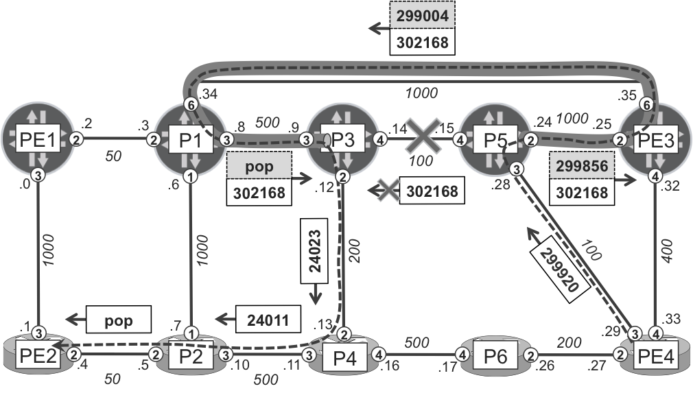
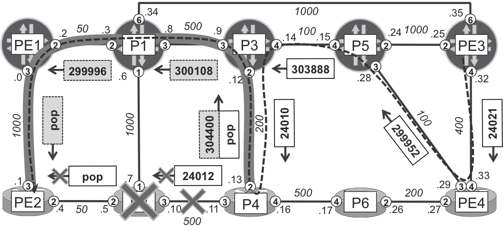
Let’s get back to the PE3--->PE2 regular LSP. When the P5→P3 link (or the P3 node) fails, the PLR (P5) removes the primary next hop (via ge-2/0/4 toward P3, label swap 303500), and only the backup next hop (using bypass LSP P5-PE3-P1-P2-P4) remains, as visible in Figure 19-7 and in Example 19-34.
Example 19-34. Routing entry for PE3--->PE2 LSP on P5 (Junos)
1     juniper@P5> show route label 301136 detail | match <pattern>
2     301136 (1 entry, 1 announced)
3                     Next hop: 10.0.0.25 via ge-2/0/2.0, selected
4                     Label-switched-path P5-PE3-P1-P2-P4
5                     Label operation: Swap 24024, Push 300080(top)
To maintain the local protection state shown in Figure 19-7, the definition of the PE3--->PE2 LSP was changed to a strict ERO, and therefore global protection (new path calculation performed at the head-end router) does not succeed. The following traceroute is targeted to the VPN loopback prefix on PE2; thus, traffic follows the PE3--->PE2 LSP (PE3→PE4→P5→P3→P4→P2→PE2), patched by the NNHOP bypass LSP to avoid the failed P3 node (P5→PE3→P1→P2→P4). The bottom MPLS label corresponds to the VPN service and is not shown in Figure 19-7.
Example 19-35. Facility protection in action (Junos)
The first label (PE3--->PE2) is swapped on each node, whereas the second label (VPN) remains constant. Now, when arriving at P5, traffic is redirected over the NNHOP bypass LSP in order to avoid the P3 node. This bypass LSP terminates on P4, so you can see up to P2 node (the penultimate node for the NNHOP bypass LSP) three labels:
The first label is the NNHOP bypass LSP label, and it is swapped at each hop.
The second label is the PE3--->PE2 regular LSP label allocated by NNHOP node, and it remains constant inside the bypass.
The third label is the VPN label, and it remains constant end to end.
Before P2 sends the traffic to P4 along the NNHOP bypass LSP, it removes the NNHOP label (PHP); thus, traffic arrives to P4 with only two labels (PE3--->PE2 + VPN). From this point, it continues normally along the PE3--->PE2 regular LSP up to PE2.
So, the protection works as expected! However, from what you can see, the path taken during protection (PE3→PE4→P5→PE3→P1→P2→P4→P2→PE2) is certainly suboptimal. Nodes PE3 and P2 are visited twice, for example. Such suboptimal paths are typical in a facility protection scheme, because the bypass LSP simply patches the failed facility (link or node). Facility protection does not try to make end-to-end optimal backup paths, but such a suboptimal forwarding state typically takes a relatively short time for regular LSPs with dynamic path option. As already discussed, in the meantime the head-end router performs CSPF for the regular LSP, so this LSP is eventually signaled to a different, more optimal path that avoids failed links.
But how does the head-end router realize that facility protection is active? It gets the information via appropriate flags in the RECORD ROUTE object. Let’s check that.
Example 19-36. RECORD ROUTE object with “Local Protection in Use” flag (Junos)
You can see that 172.16.0.5 (loopback of P5) is reported with 0x2b flags. In other words, the following flags are set (see RFC 4090, Section 4.4, and Example 19-23, where meaning of these flags is shown):
0x01
Local protection available
0x02
Local protection in use
0x08
Node protection available
0x20
Address specifies a Node-ID address
0x01 + 0x02 + 0x08 + 0x20 = 0x2b. Because the flag 0x02 is set by the P5 node, PE3 knows that local protection is used (active) for forwarding at P5. Flag 0x02 is not set at other nodes; thus, other nodes do not use local protection. However, because flag 0x01 is set on all the nodes, local protection is available (ready), and can be immediately used, if downstream failure happens as per the reporting node. In other words, there are bypass LSPs available to protect all the links, and one of these bypass LSPs is currently active.
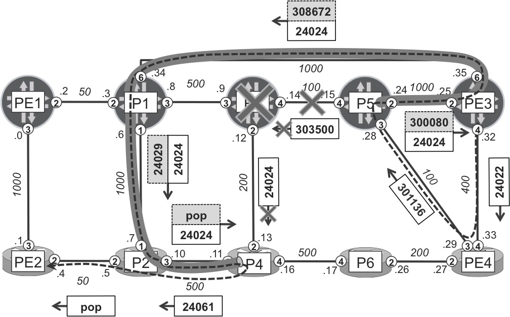
Now, let’s examine facility protection in action on the IOS XR plane. For the purposes of this verification, the PE4--->PE2 regular LSP is bound (via an explicit path option) to the PE4→P6→P4→P2→PE1 path prior to simulating the P6→P4 link (or P4 node) failure. To match Figure 19-8 to Example 19-37, remember that for space reasons Figure 19-8 does not show the VPN label, which remains constant all the way from PE4 to PE2.
Similar to the previously observed Junos case, you can see traffic being redirected over the NNHOP bypass LSP, which follows the P6→PE4→P5→P3→P1→P2 path. You can also observe the flag 0x02 (Local protection in use) being set (line 15) in addition to some other flags. And, finally, facility protection is now active on P6 router (line 35).
Automatic Protection Bypass
Creating bypass LSPs manually, as done so far in this chapter, might be a very challenging task. Fortunately, both IOS XR and Junos offer the possibility of automatic bypass LSP creation, as configured in Example 19-38 and Example 19-39. This is similar to the automatic bypass tunnels for extending LFA coverage discussed in Chapter 18.
Example 19-38. Automatic bypass tunnel configuration (IOS XR)
group GR-MPLS-TE
 mpls traffic-eng
  interface 'GigabitEthernet.*'
   auto-tunnel backup
end-group
!
ipv4 unnumbered mpls traffic-eng Loopback0
!
mpls traffic-eng
 apply-group GR-MPLS-TE
 auto-tunnel backup
  tunnel-id min 101 max 199
Example 19-39. Automatic bypass tunnel configuration (Junos)
In both IOS XR and Junos, you enable automatic bypass tunnel creation on an interface basis, using the auto-tunnel backup or link-protection keywords, respectively. RSVP-TE auto tunneling has been already discussed in Chapter 2 and Chapter 5. Using groups simplifies the configuration of multiple interfaces, and the regular expression in Example 19-39 matches both Ethernet and SONET interfaces.
Note
In IOS XR, manual and automatic bypass tunnel configuration cannot coexist on the same interface. In Junos, they can, and manual bypass tunnel is preferred. If a manual bypass tunnel is not operational (not configured or configured but in down state), Junos establishes an automatic bypass tunnel.
Additionally, let’s request node-link protection (refer to Example 19-31 and Example 19-33) for all regular tunnels and verify the state of the network, as demonstrated in Example 19-40.
Example 19-40. Bypass LSPs on PE1 (Junos)
juniper@PE1> show rsvp session | match <pattern>
Ingress RSVP: 7 sessions
To              From            LSPname
172.16.0.1      172.16.0.11     Bypass->10.0.0.3
172.16.0.3      172.16.0.11     Bypass->10.0.0.3->10.0.0.9
172.16.0.22     172.16.0.11     Bypass->10.0.0.1
172.16.0.33     172.16.0.11     Bypass->10.0.0.3->10.0.0.35
Egress RSVP: 6 sessions
To              From            LSPname
172.16.0.11     172.16.0.22     autob_PE2_t101_Gi0_0_0_3
172.16.0.11     172.16.0.33     Bypass->10.0.0.34->10.0.0.2
172.16.0.11     172.16.0.1      Bypass->10.0.0.2
Transit RSVP: 4 sessions
To              From            LSPname
172.16.0.2      172.16.0.22     autob_PE2_t103_Gi0_0_0_2
172.16.0.4      172.16.0.22     autob_PE2_t102_Gi0_0_0_2_172.16.0.2
172.16.0.22     172.16.0.2      autob_P2_t102_Gi0_0_0_2
As you can see, IOS XR and Junos (look at the column labeled From) follow different naming conventions for automatic bypass tunnels. Let’s review the terminology:
NHOP (link protection) bypass tunnel
Junos:Bypass-><NHOP-LINK-IP>
For example, the NHOP bypass tunnel started on PE1 to protect traffic forwarded via PE1→P1 (ge-2/0/2.0, NHOP-LINK-IP = 10.0.0.3) link:
Bypass->10.0.0.3
IOS XR:autob_<S-NODE>_t<ID>_<S-INTF>
For example, the NHOP bypass tunnel started on PE2 to protect traffic forwarded via PE2→P2 (Gi0/0/0/2, NHOP-LINK-IP = 10.0.0.5) link:
autob_PE2_t103_Gi0_0_0_2
NNHOP (node and link protection) bypass tunnel
Junos:Bypass-><NHOP-LINK-IP>-><NNHOP-LINK-IP>
For example, the NNHOP bypass tunnel started on PE1 to protect traffic forwarded through P1 node (NHOP-LOOPBACK-IP=172.16.0.1) via PE1→P1→P3 path (ge-2//0/2.0, NHOP-LINK-IP = 10.0.0.3, NNHOP-LINK-IP = 10.0.0.9):
For example, the NNHOP bypass tunnel started on PE2 to protect traffic forwarded through P2 node (NHOP-LOOPBACK-IP=172.16.0.2) via PE2→P2→P4 path (Gi0/0/0/2, NHOP-LINK-IP = 10.0.0.5, NNHOP-LINK-IP = 10.0.0.11):
autob_PE2_t102_Gi0_0_0_2_172.16.0.2
It’s noteworthy that the automatic bypass feature generates a single NHOP bypass tunnel per protected link. However, multiple NNHOP tunnels might be created, depending on the regular LSPs transiting the NHOP node. If in Figure 19-8 you temporarily change the metric of the P1-P2 to 200, regular tunnels from PE1 and PE2 will take following paths:
PE1--->PE2 tunnel: PE1→P1→P2→PE2
PE1--->PE3 tunnel: PE1→P1→PE3
PE1--->PE4 tunnel: PE1→P1→P3→P5→PE4
PE2--->PE1 tunnel: PE2→P2→P1→PE1
PE2--->PE3 tunnel: PE2→P2→P1→PE3
PE2--->PE4 tunnel: PE2→P2→P4→P3→P5→PE4
For all three regular tunnels starting from PE1, the NHOP is the same node (P1). Similarly, for all three regular tunnels starting from PE2, the NHOP is P2. However, three NNHOP automatic bypass tunnels are created on PE1, because NNHOPs are different for each regular LSP started from PE1 (NNHOPs are P2, PE3, and P3, respectively). On PE2, two NNHOP bypass tunnels are required, as two different NNHOPs are used (P1 and P4). Let’s verify that in the following two examples:
Example 19-41. NNHOP tunnel status on PE1 (Junos)
juniper@PE1> show rsvp interface ge-2/0/2.0 extensive | match ...
Protection: On, Bypass: 3, LSP: 3, Protected LSP: 3,
                                   Unprotected LSP: 0
  Bypass: Bypass->10.0.0.3->10.0.0.7, State: Up, Type: NP, LSP: 1
  Bypass: Bypass->10.0.0.3->10.0.0.9, State: Up, Type: NP, LSP: 1
  Bypass: Bypass->10.0.0.3->10.0.0.35, State: Up, Type: NP, LSP: 1

juniper@PE1> show route table inet.3 protocol rsvp
(...)
172.16.0.22/32 *[RSVP/7/1] 00:53:08, metric 300
      > to 10.0.0.3 via ge-2/0/2.0, LSP PE1--->PE2
        to 10.0.0.1 via ge-2/0/3.0, LSP Bypass->10.0.0.3->10.0.0.7
172.16.0.33/32 *[RSVP/7/1] 03:16:55, metric 1050
      > to 10.0.0.3 via ge-2/0/2.0, LSP PE1--->PE3
        to 10.0.0.1 via ge-2/0/3.0, LSP Bypass->10.0.0.3->10.0.0.35
172.16.0.44/32 *[RSVP/7/1] 03:16:54, metric 750
      > to 10.0.0.3 via ge-2/0/2.0, LSP PE1--->PE4
        to 10.0.0.1 via ge-2/0/3.0, LSP Bypass->10.0.0.3->10.0.0.9
Example 19-42. NNHOP tunnel status on PE2 (IOS XR)
In Junos, you can easily determine for which NNHOP the bypass is established, because NHOP and NNHOP link addresses are encoded in the bypass tunnel name. In IOS XR, you need to execute more commands to find that out.
The RSVP-TE facility protection design is now final. All regular tunnels are protected against transit node and link failures, and appropriate states (primary and backup next hops) are created on all routers. There is 100% backup coverage for both node and link failures. Compared to the much more extensive efforts required to achieve 100% backup coverage with LFA, you can see that RSVP-TE is much simpler. You simply need to enable automatic bypass tunnels, and request node and link protection for regular tunnels, and you are done.
Note
The semantics of the Junos node-link-protection keyword used in LFA and RSVP-TE facility protection configurations is slightly different. In LFA, backup next hop is selected only if it fulfills both node and link-protection criteria. In RSVP-TE facility protection, the backup next hop that fulfills node-protection criterion is preferred, but if not found, the backup next hop that fulfills link protection criterion is used. To achieve similar behavior in LFA, you must additionally use the node-link-degradationkeyword.
RSVP-TE One-to-One Protection
Whereas you can consider facility protection a rough equivalent of per-link LFA, you can view one-to-one protection as a rough equivalent of per-prefix LFA (in the analogy, replace prefixes with protected RSVP-TE LSPs). In one-to-one protection, each eligible regular tunnel is protected independently with separate detour LSPs.
With facility backup, during a failure event, traffic belonging to multiple regular tunnels might be forwarded (tunneled) over a single bypass LSP. In one-to-one backup, detour LSPs are associated with a single regular tunnel only; thus, traffic on that single tunnel might use its associated detour LSPs during a failure event. The native merging feature, which will be explained soon, reduces the impact of these detours in terms of scalability.
You can view one-to-one protection as an extension of the RSVP-TE path protection concept discussed earlier in this chapter. In path protection, the head-end router creates the primary and secondary (standby) LSP and performs switchover to the secondary LSP upon failure of the primary LSP. The head-end can detect a failure of the directly connected neighbor relatively fast. However, detecting a failure of transit nodes used by the primary path farther away from the head-end might take some time. Thus, switchover to the secondary standby LSP might be delayed, which is a clear limitation of the path protection scheme.
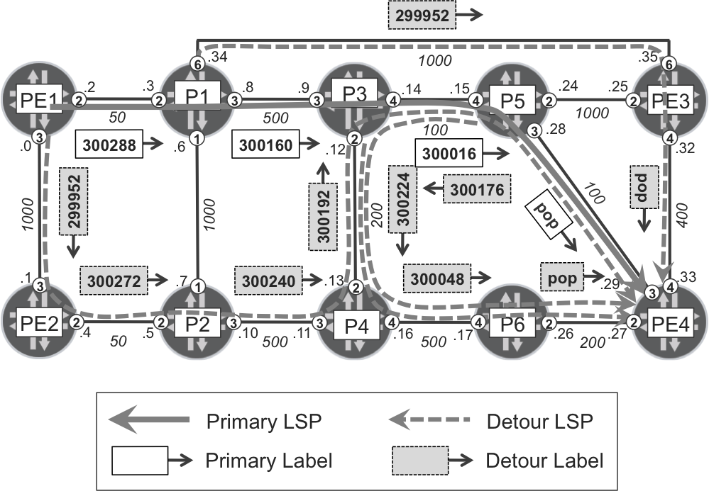
The one-to-one backup concept overcomes this limitation through automatic creation of secondary standby LSPs at each transit node along the primary path. These secondary standby LSPs are called detour LSPs in one-to-one backup architecture. Apart from the name itself, another difference is that detour LSPs don’t need to be completely disjointed from the primary path. It is enough if they are disjointed until the NNHOP only, because protection against failure of the NNHOP is handled by the detour LSP initiated at the next hop. This concept is illustrated in Figure 19-9.
Note
As of this writing, support for one-to-one backup was available in Junos but not in IOS XR.
Figure 19-9. One-to-one backup with detour LSPs
From a configuration perspective, you simply need to enable one-to-one protection for each LSP that you want to protect, as demonstrated in Example 19-43.
Before starting this section, all RSVP-TE tunnels (full mesh between PE routers) are set back to their basic state (single, dynamic path option per tunnel) and all the facility protection specific configurations removed.
Example 19-43. One-to-one protection configuration (Junos)
The fast-reroute keyword used in RSVP-TE tunnel configurations in IOS XR and Junos has completely different meanings. In IOS XR, it designates specific RSVP-TE tunnels as eligible for facility (link or node) protection. Exactly the same keyword in Junos results in enabling one-to-one protection for a specific RSVP-TE tunnel. Consult Table 19-1 for the terminology used by RFC 4090. Also check the documentation for both vendors.
The primary LSP for PE1--->PE4 tunnel is established via the shortest path, which is PE1→P1→P3→P5→PE4. Additionally, the head-end router as well as each transit (mid-point) router presignal the detour LSPs. Let’s verify, at least on three first nodes from regular LSP, what paths are selected for these detour LSPs (see Example 19-44).
Example 19-44. Detour LSPs for PE1→PE4 LSP
1     juniper@PE1> show rsvp session name PE1--->PE4 extensive | match ...
2       Detour is Up
3       Detour Explct route: 10.0.0.1 10.0.0.5 10.0.0.11 10.0.0.12
4                            10.0.0.15 10.0.0.29
5       Detour Record route: <self> 10.0.0.1 10.0.0.5 10.0.0.11 10.0.0.12
6                            10.0.0.15 10.0.0.29
7       Detour Label out: 299952
8
9     juniper@P1> show rsvp session name PE1--->PE4 extensive | match ...
10      Detour is Up
11      Detour Explct route: 10.0.0.35 10.0.0.33
12      Detour Record route: 10.0.0.2 <self> 10.0.0.35 10.0.0.33
13      Detour Label out: 299952
14
15    juniper@P3> show rsvp session name PE1--->PE4 extensive | match ...
16      Detour is Up
17      Detour Explct route: 10.0.0.13 10.0.0.17 10.0.0.27
18      Detour Record route: 10.0.0.2 10.0.0.8 <self> 10.0.0.13 10.0.0.17
19                           10.0.0.27
20      Detour Label out: 300224
21    Detour branch from 10.0.0.0, to skip 172.16.0.1, Up
22      Explct route: 10.0.0.15 10.0.0.29
23      Record route: 10.0.0.0 10.0.0.4 10.0.0.10 10.0.0.13 <self>
24                    10.0.0.15 10.0.0.29
25      Label in: 300192, Label out: 300016
26    Detour branch from 10.0.0.15, to skip 172.16.0.44, Up
27      Explct route: 10.0.0.13 10.0.0.17 10.0.0.27
28      Record route: 10.0.0.2 10.0.0.8 10.0.0.14 10.0.0.15 <self>
29                    10.0.0.13 10.0.0.17 10.0.0.27
30      Label in: 300176, Label out: 300224
The path for the detour LSP is by default the shortest path to the destination (PE4), which avoids the primary next-hop node (or link to primary next-hop in case of the penultimate node: P5). That is:
Detour from PE1:
PE1→PE2→P2→P4→P3→P5→PE4 (avoid P1 node, lines 3 through 6 and 21 through 24)
Detour from P1
P1→PE3→PE4 (avoid P3 node, lines 11 and 12)
Detour from P3
P3→P4→P6→PE4 (avoid P5 node, lines 17 and 18)
Detour from P5
P5→P3→P4→P6→PE4 (avoid P5→PE4 link, lines 26 through 29)
As you can see, the detour LSP to skip the NHOP node doesn’t necessarily traverse the NNHOP node (in case of facility backup with node protection, automatic bypass LSP always terminates on the NNHOP node). For example, the detour from P1 to skip node P3 does not traverse P5 (which is the NNHOP node). Put simply, the shortest path from P1 to PE4 that avoids P3 is not via P5.
Another observation is the fact that some detour LSPs use (partially) overlapping paths with another detour LSP or with a primary LSP. For example, the detour LSP from P3 and the detour LSP from P5 have a common P3→P4→P6→PE4 segment (lines 18, 19, 28, and 29). Similarly the detour LSP from PE1 shares the P3→P5→PE4 segment with the primary path.
One-to-one backup architecture is clever enough to realize this and merge LSPs (multiple detour LSPs or the detour LSP with the primary LSP) to avoid wasting resources. When the detour LSP from P3 and the detour LSP from P5 are merged together in one LSP at P3 (the merge node), P3 uses one single RSVP Path message in the downstream segment. Indeed, downstream from the merge node, there is only one label allocated for the two merged LSPs (lines 20 and 30).
To signal detour LSPs and keep track of merged detour LSPs, RFC 4090 introduces an additional RVSP-TE object: DETOUR object. The DETOUR object is basically a list of [PLR_ID, Avoid_Node_ID] pairs. Each pair represents a single detour LSP. For example, [10.0.0.12, 172.16.0.5] represents a detour LSP started at P3 (10.0.0.12) to avoid P5 (172.16.0.5) node. Let’s see how a single RSVP-TE Path message, captured on the P4→P6 link, is used for multiple (merged) detour LSPs (from P3, and from P5).
Example 19-45. RSVP-TE Path message with DETOUR object
[linux:~/Downloads] juniper% tshark -r rsvp-path-merge.pcap -V
(...)
 Resource ReserVation Protocol (RSVP): PATH Message. SESSION:
   IPv4-LSP, Destination 172.16.0.44, Short Call ID 0,
   Tunnel ID 54692, Ext ID ac10000b. SENDER TEMPLATE: IPv4-LSP,
   Tunnel Source: 172.16.0.11, Short Call ID: 0, LSP ID: 1.
(...)
     DETOUR:
         Length: 20
         Object class: DETOUR object (63)
         C-type: 7
         PLR ID 1: 10.0.0.12
         Avoid Node ID 1: 172.16.0.5
         PLR ID 2: 10.0.0.15
         Avoid Node ID 2: 172.16.0.44
Another way to verify the LSP merging operation is to check the MPLS routing entries for incoming labels of different LSPs that are eligible for merging (in this case, the primary path, and the detour from PE1).
Example 19-46. Merging operation at merge node P3
1     juniper@P3> show route label 300160 detail | match <pattern>
2     300160 (1 entry, 1 announced)
3            Next hop: 10.0.0.15 via ge-0/0/4.0 weight 0x1, selected
4              Label-switched-path PE1--->PE4
5              Label operation: Swap 300016
6            Next hop: 10.0.0.13 via ge-0/0/2.0 weight 0x4001
7              Label-switched-path PE1--->PE4
8              Label operation: Swap 300224
9
10    juniper@P3> show route label 300192 detail | match <pattern>
11    300192 (1 entry, 1 announced)
12           Next hop: 10.0.0.15 via ge-0/0/4.0 weight 0x1, selected
13             Label-switched-path PE1--->PE4
14             Label-operation: Swap 300016
In Example 19-46, the incoming label 300160 (primary LSP) is swapped to label 300016 (line 5) when sent via ge-0/0/4.0 (primary next hop). At the same time, label 300192 (detour LSP from PE1 to avoid P1) is swapped to label 300016 (line 14), too, effectively merging two LSPs (primary + detour from PE1) downstream of the P3 node.
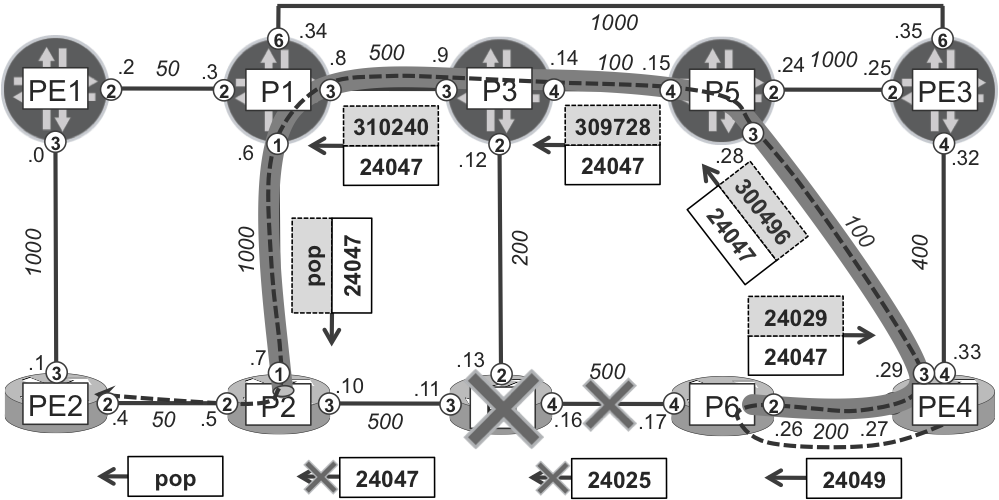
Example 19-47 simulates the P3→P5 link failure and performs traceroute to a PE4’s VPN prefix for verification (again, during this verification the primary path was statically fixed using an explicit path option). The VPN label is 16 and remains constant.
Example 19-47. One-to-one protection in action (Junos)
juniper@PE1> traceroute 192.168.1.44 routing-instance VRF-A
 1  P1 (10.0.0.3)  13.831 ms  7.650 ms  6.315 ms
     MPLS Label=300288 CoS=0 TTL=1 S=0
     MPLS Label=16 CoS=0 TTL=1 S=1
 2  P3 (10.0.0.9)  6.668 ms  5.828 ms  6.962 ms
     MPLS Label=300160 CoS=0 TTL=1 S=0
     MPLS Label=16 CoS=0 TTL=2 S=1
 3  P4 (10.0.0.13)  8.084 ms  5.744 ms  7.895 ms
     MPLS Label=300224 CoS=0 TTL=1 S=0
     MPLS Label=16 CoS=0 TTL=3 S=1
 4  P6 (10.0.0.17)  5.673 ms  6.361 ms  7.924 ms
     MPLS Label=300048 CoS=0 TTL=1 S=0
     MPLS Label=16 CoS=0 TTL=4 S=1
 5 PE4-VRF-A (192.168.1.44) 6.075 ms 6.625 ms 6.421 ms
From traceroute, it is obvious that P3 realizes the link failure and uses a backup next hop (lines 6 and 8 in Example 19-46) to forward the traffic via the P3→P4→P6→PE4 detour LSP. If you compare typical traceroute when facility protection is active (Example 19-35 and Example 19-37) with traceroute when one-to-one protection is active, you can spot two major differences:
Facility protection results in an additional label (bypass LSP) being pushed on the label stack; thus, the resulting label stack is bigger (increased from two to three labels in the examples). One-to-one backup, on the other hand, doesn’t cause label stack increase, because the label action on the backup next hop is swap (line 8 in Example 19-46) and not swap/push (line 8 in Example 19-24). In the PHP case, the label action in one-to-one is pop, as compared to swap in facility protection.
The path taken by traffic during active protection is typically more optimal with one-to-one backup, because one-to-one detour LSPs are established over the shortest post-convergence path to the final destination (avoiding protected node). In facility backup, on the other hand, the bypass LSPs are established only to the NHOP or NNHOP node, resulting typically in suboptimal traffic forwarding during failures.
So, which is better: facility backup or one-to-one backup? The answer is: it depends! One-to-one backup provides more optimal backup paths. Additionally, it has the ability to spread backup paths of multiple regular LSPs using the same resource (link and node), because detour LSPs are separate for each regular LSP. Thus, during failure, traffic originally flowing along the same (failed) link might be forwarded over different paths, minimizing the possible likelihood of intermittent congestion. In facility protection, traffic is forwarded over the same bypass LSP; consequently, intermittent congestion might occur. Conversely, one-to-one protection results in more RSVP-TE states that need to be maintained in the network, because detours are specific to each regular LSP. Table 19-2 provides a comparison between the total number of RSVP sessions (first row: regular + bypass LSPs, second row: regular + detour LSPs) that need to be maintained at each node using the example topology from this section. The table assumes full mesh of regular LSPs between PE routers, and the desire for both node and link protection.
Table 19-2. Comparison of facility protection and one-to-one protection
Type
P1
P2
P3
P4
P5
P6
PE1
PE2
PE3
PE4
Facility
13
16
15
16
13
5
13
16
12
18
One to One
19
16
20
19
16
8
16
16
15
23
As more and more regular LSPs are added to the network, the differences might be greater.
Note
One-to-one protection is especially advantageous in ring topologies, for which the suboptimal characteristic of facility backup is quite remarkable, causing a two-stage U-turn effect. Grab a piece of paper and a pencil and do the simulation yourself!
Transit Fast-Restoration Summary
A variety of local protection options to minimize traffic loss during transit link or node failures were discussed in this chapter. Which is the best? Again, the answer is: it depends. Each of the options has some advantages and disadvantages, and depending on the focus in the particular deployment, you might choose one or the other. In typical deployments, a mixture of protection technologies is used. For example, RSVP-TE based in the core network, and LFA based in the edge.
Chapter 20 and Chapter 21 discuss additional protection features, this time related to the failure of the egress PE node or egress PE-CE link.