Chapter 8. Ethernet VPN
Ethernet VPN (EVPN) is not Virtual Private LAN Service (VPLS). It is a more recent technology that aims to overcome some of the challenges that have arisen during more than a decade of VPLS live deployments.
EVPN with MPLS Transport
EVPN, formerly called MAC VPN, is described in RFC 7432 - BGP MPLS-Based Ethernet VPN.
EVPN Versus VPLS
If there was already a multipoint L2VPN solution (VPLS), why has another one been defined and implemented? Let’s compare both technologies.
EVPN versus VPLS—signaling protocols
VPLS has two possible signaling protocols, LDP and BGP, of which only BGP supports autodiscovery. EVPN takes good note of that by deprecating Targeted LDP and adopting BGP as the one and only service signaling protocol.
EVPN versus VPLS—MAC address learning
VPLS has only data-plane MAC learning, which can easily lead to stale forwarding state.
Indeed, if a local Attachment Circuit (AC) goes down, it is important to flush the associated MAC entries from the bridge table. You must do this on the local PE, and also on the remote PEs. The PW Status TLV is not a valid option, due to the lack of an AC:PW deterministic mapping in VPLS. True, VPLS has the concept of a MAC Flush flag (BGP VPLS) or TLV (LDP VPLS), but it is more like a patch than a robust solution.
Although EVPN also performs data-plane MAC learning on its local ACs, it relies on control-plane MAC learning between PEs. In fact, it uses BGP to exchange MAC address routes. This greatly reduces unknown unicast flooding and, more important, it natively implements a flush mechanism in BGP by withdrawing the BGP routes.
EVPN versus VPLS—CE Multihoming
EVPN natively implements two CE multihoming solutions: single-active (one active, N standby) and all-active (with known unicast per-flow load balancing).
True, the mechanism is complex as it involves a few route types, the election of a BUM Designated Forwarder, and so on. But it represents a breakthrough with respect to VPLS, which only implements single-active solutions. Actually, in the VPLS world, the flavors that implement a genuine albeit single-active multihoming solution are all BGP-based: BGP VPLS and LDP VPLS with BGP autodiscovery (FEC 129).
EVPN versus VPLS—Layer 2 to Layer 3 coupling
In VPLS, the Integrated Routing and Bridging (IRB) or BVI interface acts like an anchor into the Layer 3 (L3) world. But the Layer 2 (L2) and L3 worlds are quite decoupled from a state perspective. Last but not least, VPLS gateway redundancy typically relies on VRRP, which brings together some undesired effects: risk of traffic blackholing (mitigated with VRRP route or interface tracking, together with a rich set of VRRP and interface timers), traffic tromboning, complex operation, and difficult troubleshooting.
EVPN natively implements several L2-L3 hooks, as you are about to discover; this brings a native way to handle active virtual machine (VM) moves across different servers in the same data center.
EVPN Implementations
As of this writing, there are implementations of EVPN with MPLS transport, Provider Backbone Bridging[PBB]-EVPN with MPLS transport, and EVPN with Virtual eXtensible LAN (VXLAN) transport. Some of them are publicly made available at the same time as this book, so the only flavor that the authors could test in an interoperable manner is PBB-EVPN with MPLS transport. This book also includes Junos examples of the two other flavors. Stay tuned to the blog http://mplsinthesdnera.net for EVPN interoperability posts.
PBB-EVPN is more complex than EVPN, so let’s begin with EVPN. Hence, this first scenario is Junos-only (except for the BGP address family, which is shown for both vendors).
EVPN—This Book’s Topology
This book’s EVPN example focuses on the Data Center Interconnect (DCI) application. The technology remains the same for different applications, though.
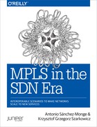
In the initial topology depicted in Figure 8-1, the CE1-PE2 and CE3-PE4 links are administratively down. They will be brought up later, in the multihoming section. So, the CE1-PE1 and CE3-PE3 connections are single-link LAGs.
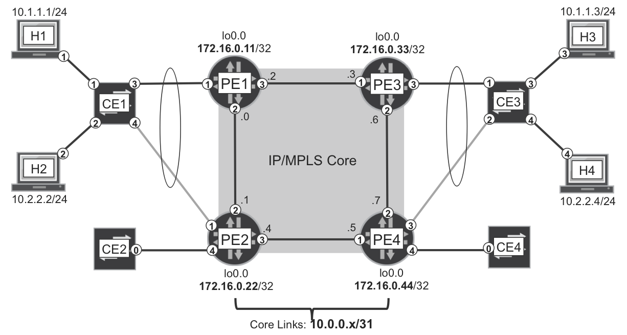
Figure 8-1. EVPN—the physical topology
H1 and H3 are connected via access (untagged) interfaces to the CEs, and they belong to VLAN 2100. Likewise, H2 and H4 belong to VLAN 2200. As for the PE-CE ACs, they are trunk (VLAN-tagged) interfaces that transport VLANs 2100 and 2200.
Although not shown in the picture, there are two Route Reflectors (RRs) with loopback addresses 172.16.0.201 and 172.16.0.202, respectively.
BGP EVPN Address Family
BGP EVPN use Multiprotocol-BGP (MP-BGP) address family: AFI=25, SAFI=70.
Example 8-1 shows how to configure the EVPN address family at a Junos PE.
Example 8-1. EVPN address family configuration—PE1 (Junos)
protocols {
    bgp {
        group iBGP-RR {
            family evpn signaling;
}}}
Adding this configuration to all the BGP groups also does the trick on Junos RRs.
Like for other BGP VPN flavors, Junos uses different RIBs for EVPN. In the language of Table 6-2, bgp.evpn.0 and <instance_name>.evpn.0 are Global Auxiliary: Raw NLRI and Instance-Specific: Raw NLRI, respectively.
Although this EVPN scenario is Junos-only, at the end of this chapter you will see an interoperable PBB-EVPN example. EVPN and PBB-EVPN use the same BGP address family. Here is the additional configuration on IOS XR PEs:
Example 8-2. EVPN address family configuration—PE2 (IOS XR)
router bgp 65000
 address-family l2vpn evpn
 !
 neighbor-group RR
  address-family l2vpn evpn
!
Note
On RRs running IOS XR, you also need to add the route-reflector-client knob under each neighbor[-group] adddress-family.
EVPN with MPLS Transport—Junos Configuration
As with VPLS, Junos has two types of routing instances that both support EVPN:
-
EVPN instances (EVIs) are more suitable for models with one single bridge domain. RFC 7432 calls these models VLAN-based.
-
Virtual Switches are the best fit for services where each VLAN must have its own bridge table and its own IRB interface. This model, called VLAN-aware bundle in RFC 7432, is the one chosen for this book’s example.
Example 8-3 shows PE1’s EVPN configuration. PE1 has one AC that is a Link Aggregation Group (LAG). Note that the Inter-Chassis Communication Protocol (ICCP) and Multichassis LAG (MC-LAG) specific commands are skipped here for brevity.
Example 8-3. EVPN MPLS on a Virtual Switch—PE1 (Junos)
1     chassis {
2         aggregated-devices ethernet device-count 20;
3     }
4     interfaces {
5         ge-2/0/1 {
6             gigether-options 802.3ad ae10;
7         }
8         ae10 {
9             flexible-vlan-tagging;
10            encapsulation flexible-ethernet-services;
11            aggregated-ether-options lacp active;
12            unit 2100 {
13                encapsulation vlan-bridge;
14                vlan-id 2100;
15            }
16            unit 2200 {
17                encapsulation vlan-bridge;
18                vlan-id 2200;
19    }}}
20    routing-instances {
21        EVPN-A {
22            instance-type virtual-switch;
23            route-distinguisher 172.16.0.11:2000;
24            vrf-target target:65000:2000;
25            protocols {
26                evpn {
27                    extended-vlan-list [ 2100 2200 ];
28                }
29            }
30            bridge-domains {
31                BR-2100 {
32                    vlan-id 2100;
33                    interface ae10.2100;
34                }
35                BR-2200 {
36                    vlan-id 2200;
37                    interface ae10.2200;
38    }}}}
Lines 23 and 24 are BGP business as usual: RDs to distinguish routes belonging to different VPNs, and RTs to control route distribution at the PEs. As for the configuration of the AC and the Virtual Switch, it follows the same principles as Example 7-9.
EVPN MPLS—Inclusive Tunnel and Autodiscovery
The Inclusive Tunnel and Provider Multicast Service Interface (PMSI) concepts have already been illustrated in the context of BGP MVPN and VPLS. In a VLAN-aware bundle EVPN service, every PE is the root of a VLAN-specific Inclusive Tunnel. This tunnel is used to send BUM traffic to all the remote PEs that also have sites in the same EVPN:VLAN.
In BGP MVPN, Inclusive Tunnels were signaled with MVPN Route Type 1. On the other hand, EVPN uses Route Type 3 for this same purpose. Indeed, EVPN uses a totally different Route Type numbering as compared to MVPN. Table 8-1 lists these route types.
| Type | Route Name |
|---|---|
| 1 | Ethernet autodiscovery (AD) route |
| 2 | MAC/IP advertisement route |
| 3 | Inclusive multicast Ethernet tag route |
| 4 | Ethernet segment (ES) route |
| 5 | IP prefix route |
Note
This book does not cover EVPN IP Prefix (Type 5) routes. For more information, see draft-ietf-bess-evpn-prefix-advertisement.
Example 8-4 shows the EVPN Type 3 routes advertised by PE1, one per VLAN.
Example 8-4. EVPN Type 3: inclusive multicast route—PE1 (Junos)
1     juniper@PE1> show route advertising-protocol bgp 172.16.0.201
2                  table EVPN-A.evpn.0 match-prefix "3:*" detail
3     [...]
4     * 3:172.16.0.11:2000::2100::172.16.0.11/304 (1 entry, 1 announced)
5      BGP group IBGP type Internal
6          Route Distinguisher: 172.16.0.11:2000
7          Nexthop: Self
8          Localpref: 100
9          AS path: [65000] I
10         Communities: target:65000:2000
11         PMSI: Flags 0x0: Label 299840:
12               Type INGRESS-REPLICATION 172.16.0.11
13
14    * 3:172.16.0.11:2000::2200::172.16.0.11/304 (1 entry, 1 announced)
15     BGP group IBGP type Internal
16         Route Distinguisher: 172.16.0.11:2000
17         Nexthop: Self
18         Localpref: 100
19         AS path: [65000] I
20         Communities: target:65000:2000
21         PMSI: Flags 0x0: Label 299856:
22               Type INGRESS-REPLICATION 172.16.0.11
So, PE1 is advertising two Type 3 routes: one for each VLAN (2100 and 2200).
These routes are called Inclusive Multicast Ethernet Tag because they provide information about the Inclusive Tunnel; they are used for BUM and they contain the VLAN ID or Tag.
The prefix format 3:<RD>:<VLAN_ID>:<ROUTER_ID_LENGTH>:<ROUTER_ID> (lines 4 and 14) is partially displayed in the previous example. Indeed, as of this writing, Junos displays everything except for the <ROUTER_ID_LENGTH>, which is invariably 32 for IPv4. The /304 mask is internal in Junos and not advertised via iBGP: you can simply ignore it. As you will see soon, Type 2 routes can also include IP information.
The BGP next hop is irrelevant for Type 3 routes: it’s there simply because it is a mandatory BGP attribute.
As of this writing, Ingress Replication (IR) is the only PMSI type implemented for EVPN. Consequently, to flood a BUM frame, the ingress PE (PE1) replicates the frame and sends one individual copy to each of the remote PEs individually. How? By using the same set of to-point (Point-to-Point [P2P] or Multipoint-to-Point [MP2P]) LSPs that are used for unicast services. The MPLS label encoded in the PMSI attribute (lines 11 and 21) is the VPN label, which is stacked below the transport label.
One important aspect of the MPLS labels included in the PMSI attribute (lines 11 and 21) is that they are downstream-allocated labels. Exactly as in BGP MVPN with IR transport, PE1 uses the PMSI attribute to specify that:
-
As a root PE, PE1 uses an Inclusive Tunnel based on IR to send frames to remote PEs—pushing the service labels specified by the remote PEs.
-
As a leaf PE, PE1 expects to receive frames with the MPLS label value included in the PMSI attribute that it generates: in the example, label 299840 for VLAN 2100, and label 299856 for VLAN 2200.
Figure 5-6 illustrates the IR mechanism for BGP MVPN, similar to the EVPN one except that the to-point tunnels transport L3 packets instead of L2 frames.
EVPN with MPLS Transport—Advertising MACs
EVPN was once called MAC VPN because it implements MAC route advertising. One important aspect of MAC addresses, as compared to IP, is that MAC addresses do not support any subnetting. Two hosts connected to the same L2 switch and in the same VLAN can have completely different MAC addresses; to the point that the first bytes of a MAC address identify the network adapter’s vendor.
This means that EVPN advertises one MAC route per host: there is no possibility to aggregate them. PBB EVPN changes this rule a bit, as you will see later.
Every bridge domain in the EVPN instance performs independent MAC learning. As soon as a new source MAC address is learned on an AC, the PE advertises a MAC route. These are EVPN Type 2 routes, corresponding to H1’s MAC address:
Example 8-5. EVPN Type 2: MAC Advertisement route—PE1 (Junos)
1     juniper@PE1> show route advertising-protocol bgp 172.16.0.201
2                  table EVPN-A.evpn.0 match-prefix "2:*" detail
3     [...]
4     * 2:172.16.0.11:2000::2100::5c:5e:ab:0a:c3:92/304 (1 entry, ...)
5      BGP group IBGP type Internal
6          Route Distinguisher: 172.16.0.11:2000
7          Route Label: 299776
8          ESI: 00:00:00:00:00:00:00:00:00:00
9          Nexthop: Self
10         Localpref: 100
11         AS path: [65000] I
12         Communities: target:65000:2000
13    /* Other routes omitted */
The prefix format is 2:<RD>:<VLAN_ID>:<MAC_LENGTH>:<MAC_ADDRESS> (line 4). Junos does not display the <MAC_LENGTH>, which is invariably 48. The /304 mask is internal in Junos and not advertised via IBGP: you can simply ignore it.
With the Route Label 299776, PE1 is telling the remote PEs if you receive a frame from a local AC in EVPN-A, and the bridge domain is associated to VLAN 2100, and the destination MAC address is 5c:5e:ab:0a:c3:92, send it to me with VPN label 299776.
Because PE1 learned H1’s MAC address through a frame received from a single-homed CE, the Ethernet Segment Identifier (ESI) is set to 0x0 (line 8). PEs map to ESI #0 all the ACs connected to either single-homed CEs or single-active multihomed CEs.
Only MAC addresses learned on all-active multihomed CEs have a non-zero ESI value. How do PEs realize whether the CE is single-homed or multihomed? Actually, they don’t. It is up to the network administrator or an external software to configure a non-zero ESI on each AC that is connected to an all-active multihomed CE. EVPN ESIs and VPLS CE-IDs have points in common, but also differences, as explained later on.
EVPN with MPLS Transport—Intra-VLAN Bridging
The two previously described EVPN route types are enough to enable bridging among hosts in the same VLAN. The full sequence is illustrated in Figure 8-2. Read it from top to bottom. In this chapter, the control-plane signaling is shown with round corners, and the forwarding-plane units are shown with sharp corners. The outermost headers are displayed on top, and the external Ethernet headers at the core links are omitted.
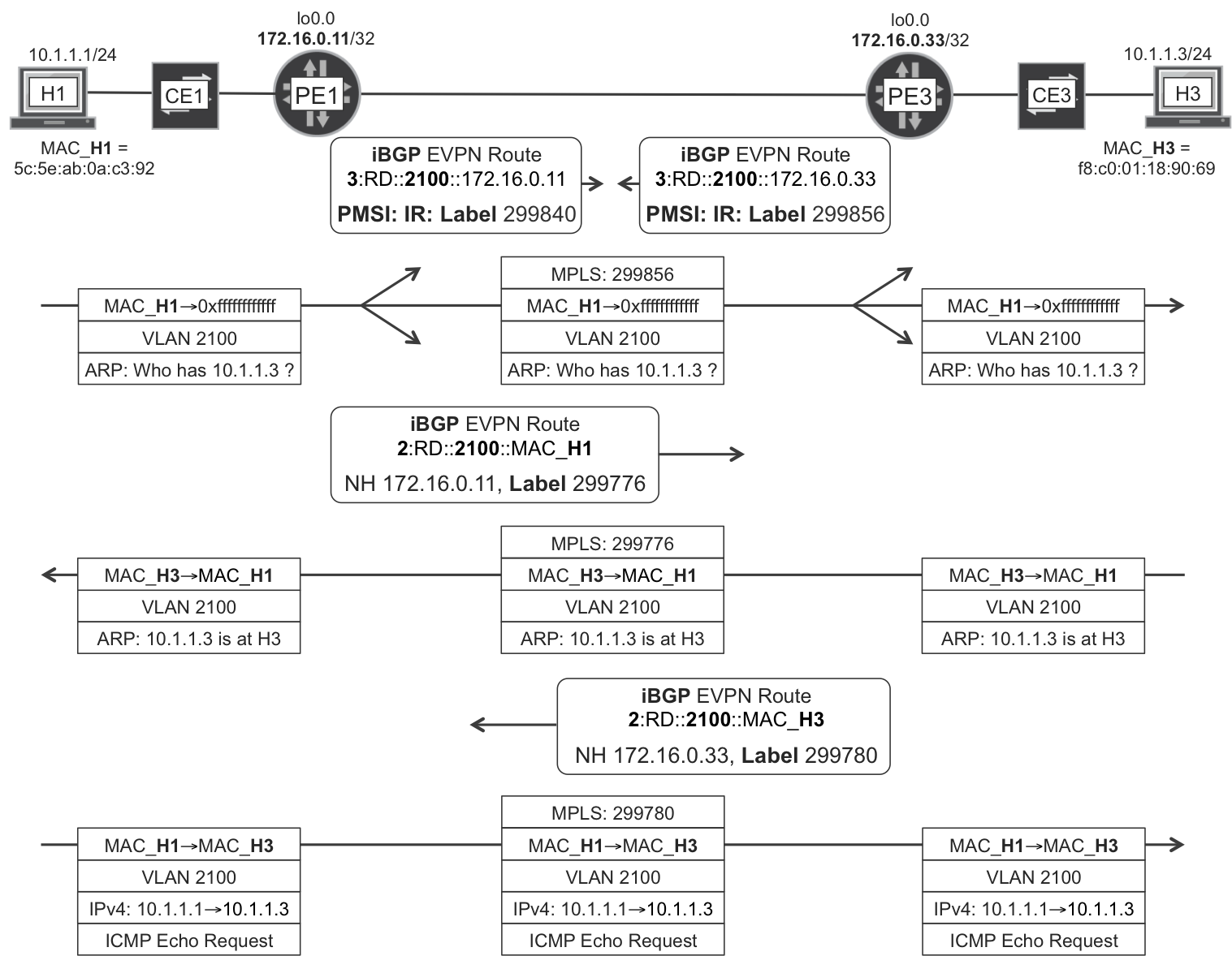
Figure 8-2. EVPN—intra-VLAN bridging
You can check that MAC learning takes place thanks to EVPN MAC Advertisement (Type 2) routes. This is an important difference as compared to VPLS, and it allows a PE to advertise the same label to all the remote PEs. Because MAC learning takes place in the control plane, in EVPN it is no longer necessary to know from which remote PE the frame arrives.
This example has no transport label because the PEs are directly connected to each other. Otherwise, label stacking would take place and the transport label would be the top of the stack, and then removed at the penultimate hop: MPLS VPN + PHP business as usual.
The broadcast frame (ARP request sent from H1) uses the Inclusive Tunnel, so it is flooded to all the remote PEs. On the other hand, unicast frames (ARP reply and ICMP echo request) are only sent to one remote PE, thanks to MAC learning. Note that EVPN Type 3 (Inclusive Multicast) and Type 2 (MAC Advertisement) use different MPLS label values, and so does BUM versus known unicast traffic.
Note
Like in VPLS, there is a default split horizon rule in EVPN: a tunneled frame received from the core is not forwarded back to the core (to any PE). This is essential to prevent L2 loops.
Finally, there is a strong coupling between a bridge domain’s MAC table and the EVPN Type 2 (MAC Advertisement) routes. If the H1 entry in PE1’s MAC table expires due to traffic inactivity, or if it is manually cleared, PE1 withdraws H1’s MAC Advertisement route. This triggers a MAC table entry flush in the remote PEs. MAC Advertisement routes synchronize all the PEs’ MAC tables. It is the BGP way to program a distributed switch.
The MAC tables can be checked with the commands show evpn mac-table (for EVPN instances) or show bridge mac-table (for Virtual Switches).
EVPN with MPLS Transport—Inter-VLAN Forwarding
One of the key advantages of EVPN over VPLS lies on the integration of the L2 and L3 worlds. Let’s see that in detail.
EVPN IRB—Junos configuration
It’s time to allow H1 and H3 (VLAN 2100) to communicate to H2 and H4 (VLAN 2200). IRB in VPLS and IRB in EVPN are configured in a similar way. However, if we look closely, the implementation is very different, making EVPN a superior solution.
Typically, the IRB interfaces are placed in an L3 VRF. Unlike VPLS, the EVPN instance is tightly coupled to the L3 VRF(s) where its IRBs are placed. Example 8-6 shows the configuration at PE1, where this tight coupling is not obvious yet.
Example 8-6. EVPN IRB configuration—PE1 (Junos)
1     interfaces {
2         irb {
3             unit 2100 {
4                 family inet address 10.1.1.100/24;
5                 mac 00:00:0a:01:01:64;
6             }
7             unit 2200 {
8                 family inet address 10.2.2.200/24;
9                 mac 00:00:0a:02:02:c8;
10    }}}
11    routing-instances {
12        VRF-A {
13            instance-type vrf;
14            interface irb.2100;
15            interface irb.2200;
16            route-distinguisher 172.16.0.11:1234;
17            vrf-target target:65000:1234;
18            vrf-table-label;
19        }
20        EVPN-A {
21            protocols {
22                evpn {
23                    default-gateway advertise;
24            }}
25            bridge-domains {
26                BR-2100 {
27                    routing-interface irb.2100;
28                }
29                BR-2200 {
30                    routing-interface irb.2200;
31    }}}}
The new L3 VRF has different RD (line 16) and RT (line 17), with respect to the EVPN Virtual Switch instance (Example 8-3, lines 23 and 24).
A very important aspect of the previous example is the fact that the IRB MAC addresses are manually derived from the IPv4 address. This is a method to ensure that if two PEs have the same IRB IPv4 address on a given bridge domain, they also have the same IRB MAC address on that domain. Why do this? Imagine that, for a given VLAN, you set the same IRB IPv4 and MAC addresses on all the PEs. This makes it possible to seamlessly move an active VM from one site to another or even from one data center to another. The VM would keep its original ARP entry pointing to its default gateway, remaining valid! On the down side, it is not possible to ping the individual IRB interfaces in a precise manner, and the solution to this challenge is briefly mentioned later.
Strictly speaking, it would even be possible to set the same MAC address on all the IRBs of all the bridge domains; but keeping a per-VLAN unique MAC is typically enough.
VPLS cannot use the same trick. You will see why in a few pages.
Just one more implementation detail: modern Junos releases enable chained-composite-next-hop for EVPN by default. You need to confirm that this is the case in your Junos PEs; otherwise, you need to configure it explicitly. Indeed, it is required by the L2 rewrites that take place during inter-VLAN forwarding at the ingress PE.
Example 8-7. EVPN chained composite next hop—PE1 (Junos)
juniper@PE1> show configuration groups junos-defaults routing-options
forwarding-table {
    export evpn-pplb;
    chained-composite-next-hop ingress evpn;
}
EVPN IRB—new routes advertised
The previous configuration triggers a series of new routes. First, the new L3 VRF locally connected routes 172.16.0.11:1234:10.1.1.0/24 and 172.16.0.11:1234: 10.2.2.0/24. These routes are exported with RT 65000:1234 and imported in the matching L3 VRF of the remote PEs. Nothing special: just L3 VPN business as usual.
Second, for every logical IRB interface there are two new MAC/IP Advertisement routes exchanged in the context of the EVPN instance.
Example 8-8. EVPN Type 2: gateway MAC/IP Advertisement—PE1 (Junos)
juniper@PE1> show route advertising-protocol bgp 172.16.0.201
             table EVPN-A.evpn.0 match-prefix "2:*" detail
[...]
* 2:172.16.0.11:2000::2100::00:00:0a:01:01:64/304 (1 entry, ...)
     Route Label: 299776
     ESI: 00:00:00:00:00:00:00:00:00:00
     Communities: target:65000:2000 evpn-default-gateway
[...]
* 2:172.16.0.11:2000::2200::00:00:0a:02:02:c8/304 (1 entry, ...)
     Route Label: 299776
     ESI: 00:00:00:00:00:00:00:00:00:00
     Communities: target:65000:2000 evpn-default-gateway
[...]
* 2:172.16.0.11:2000::2100::00:00:0a:01:01:64::10.1.1.100/304
     Route Label: 299776
     ESI: 00:00:00:00:00:00:00:00:00:00
     Communities: target:65000:2000 evpn-default-gateway
[...]
* 2:172.16.0.11:2000::2200::00:00:0a:02:02:c8::10.2.2.200/304
     Route Label: 299776
     ESI: 00:00:00:00:00:00:00:00:00:00
     Communities: target:65000:2000 evpn-default-gateway
[...]
Indeed, for each IRB (2100 and 2200), there are two EVPN Type 2 routes:
-
A good old MAC Advertisement route, which just the IRB’s MAC in the NLRI.
-
A juicier MAC/IP Advertisement route (also Type 2), which contains both the IRB’s MAC and IPv4 address in the NLRI.
Why two routes and not just one? Actually, a MAC route belongs to a pure L2 context and it is linked to the EVPN bridge domain’s MAC table. On the other hand, a MAC/IP route has an L3 side and it is linked to the L3 VRF ARP table!
Let’s learn more about this, and leave the default-gateway community for a bit later.
EVPN IRB—strong L2 to L3 coupling
Here comes one of the most interesting aspects of EVPN.
Note
EVPN PEs with IRB synchronize their ARP state with each other.
When PE1 resolves the MAC addresses of H1 (or H2) via ARP, it does two things:
-
Advertises an EVPN MAC/IP route with ARP-like mappings to the remote PEs.
-
Advertises an IPv4 VPN route with the host’s /32 address to the remote PEs.
Let’s see that for H1 (Example 8-9).
Example 8-9. EVPN Type 2: host MAC/IP Advertisement—PE1 (Junos)
1     juniper@PE1> show arp vpn VRF-A hostname 10.1.1.1
2     [...]
3     MAC Address       Address   Name       Interface       Flags
4     5c:5e:ab:0a:c3:92 10.1.1.1  10.1.1.1   ae10.2000       none
5
6     juniper@PE1> show route advertising-protocol bgp 172.16.0.201
7                  evpn-mac-address 5c:5e:ab:0a:c3:92 detail
8
9     EVPN-A.evpn.0: 24 destinations, 24 routes (24 active, ...)
10    * 2:172.16.0.11:2000::2100::5c:5e:ab:0a:c3:92/304 (1 entry, ...)
11         Route Label: 299776
12         ESI: 00:00:00:00:00:00:00:00:00:00
13         Communities: target:65000:2000
14    [...]
15    * 2:172.16.0.11:2000::2100::5c:5e:ab:0a:c3:92::10.1.1.1/304
16         Route Label: 299776
17         ESI: 00:00:00:00:00:00:00:00:00:00
18         Communities: target:65000:2000
19    [...]
20
21    juniper@PE1> show route advertising-protocol bgp 172.16.0.201
22                 table VRF-A.inet.0 10.1.1.1/32 detail
23
24    VRF-A.inet.0: 7 destinations, 13 routes (7 active, ...)
25    * 10.1.1.1/32 (1 entry, 1 announced)
26    [...]
27         VPN Label: 16
28         Communities: target:65000:1234
The EVPN MAC route (lines 10 through 13) has a pure L2 meaning, therefore it is not really related to ARP. The EVPN MAC/IP route (lines 15 through 18) is aimed to synchronize the remote PEs’ ARP bindings. Finally, the IPv4 VPN host route (lines 25 through 28) ensures that the traffic forwarding is fully optimized.
Imagine a remote IPv4 VPN PE—let’s call it PE100—that is providing access from the data center’s IPv4 VPN to different external services. PE100 might not be connected to any of the data center sites. Now let’s make it more interesting: PE100 could have no local EVPN instance at all! But thanks to the dynamically generated host /32 routes, PE100 knows exactly where to forward downstream packets. Is it PE1, or PE2, or PE3, or PE4? PE100 makes the right choice! This is a breakthrough advantage over VPLS.
Now, other PEs in the EVPN receive both the EVPN MAC/IP route and the IPv4 VPN host route for H1. Which one takes preference? By default in Junos, the EVPN MAC/IP route takes preference, so it is programmed in the forwarding table.
Example 8-10. Choosing between EVPN MAC/IP and IP VPN route—PE3 (Junos)
juniper@PE3> show route table VRF-A 10.1.1.1

VRF-A.inet.0: 7 destinations, 13 routes (7 active, ...)
+ = Active Route, - = Last Active, * = Both

10.1.1.1/32    *[EVPN/7] 00:52:41
                > to 10.0.0.2 via ge-2/0/1.0, Push 299776
                [BGP/170] 00:52:42, localpref 100, from 172.16.0.201
                  AS path: I, validation-state: unverified
                > to 10.0.0.2 via ge-2/0/1.0, Push 16
EVPN IRB in action
Let’s see how H1 in VLAN 2100 can send an IPv4 packet to H4 in VLAN 2200. For a complete learning experience, let’s take the less favorable case: for whatever reason, the PEs have not yet learned about H4’s MAC/IP mapping. PE3 not only populates its local ARP table with H4’s MAC address, it also advertises the MAC/IP mapping to all the PEs, including PE1. End of the story: now PE1 knows H4’s MAC address and the original IPv4 H1→H4 packet can reach its destination.
Figure 8-3 shows the sequence.
Figure 8-3. EVPN—Inter-VLAN forwarding
Here’s what’s happening in Figure 8-3:
-
H1 is configured with 10.1.1.100 as its default gateway. H1 resolves this address via ARP (not shown in the illustration) into MAC address 00:00:0a:01:01:64. H1 sends the frame with that destination MAC address.
-
PE1 receives the frame in the bridge domain BR-2100 and sees that the destination MAC address matches its own
irb.2100interface. PE1 removes the L2 header and performs an L3 route lookup for which the result is this: the destination is directly connected viairb.2200. -
PE1 does not know the MAC address of H4, so it sources an ARP request from its
irb.2200interface (source MAC = 00:00:0a:02:02:c8) and floods it in bridge domain BR-2200. -
H4 replies to the ARP request with an ARP reply whose destination is 00:00:0a:02:02:c8, PE1’s
irb.2200MAC address. But it’s also PE3’sirb.2200MAC address! If this was VPLS instead of EVPN, the flow would break here. This is one of the reasons why in VPLS it is not an option to use the same MAC address in different PEs. But this is EVPN, so let’s continue! -
PE3 advertises H4’s MAC/IP route to all the PEs in the EVPN, including PE1. At this point, PE1 knows H4’s MAC address, and it can forward the original frame.
So, what is the default-gateway community in Example 8-8? It is just another type of extended community. Its value is irrelevant: all that matters is whether it is present. The EVPN MAC/IP routes for the IRB addresses carry this community in order to inform the remote PEs that these addresses belong to default gateways. This mechanism is called default gateway synchronization, and in this book’s example it is not really needed. Indeed, the default gateways are already manually synchronized because all of the PEs have the same IRB IPv4 and MAC addresses configured.
The use case of automatic default gateway synchronization is a scenario in which the IRB MAC (and IPv4) addresses for a given VLAN are set to different values at each PE. If an active VM is moved by the hypervisor from one site to another, the VM still has the old ARP entry for the default gateway. The new gateway processes the frames coming from this VM because it knows that the destination MAC address actually corresponds to a default gateway somewhere in the EVPN. Although this alternative approach allows to ping the individual IRB interfaces in a precise manner, it is still a better practice to configure the same IRB IP and MAC address on every PE because it is cleaner from a forwarding perspective. An even better option is the virtual gateway functionality, which is discussed later.
EVPN—VM mobility
It is possible to move a VM live from one data center site to another by using hypervisor features such as VMware’s vMotion. The ARP cache of the VM is still valid, even the entry for the default gateway, if the IRB’s MAC/IP is the same on all PEs. This is enough to get outbound (leaving the DC site toward the core) traffic seamlessly flowing without any significant interruption.
As for inbound traffic (arriving from the core), it relies on the VM to send at least one frame so that the [EVI, VLAN] MAC table is refreshed on all the PEs. As soon as the new PE advertises a MAC/IP route for the VM, the old PE withdraws it. At this point, inbound traffic is correctly attracted to the new VM location. You can apply the same logic to each of the VM’s virtual Network Interface Cards (NICs).
Although not implemented at the time of this writing, RFC 7432 describes the MAC Mobility extended community. This new community is not strictly necessary for VM mobility, but it keeps track of MAC moves with a sequence number. If this sequence number grows abnormally fast, it is an indication of a potential L2 loop.
EVPN with MPLS Transport—All-Active Multihoming
All-active multihoming is one of the main advantages of EVPN over VPLS.
EVPN all-active—Junos configuration
As mentioned before, an EVPN AC has an ESI that is set to zero by default. This is fine for single-homed, or single-active multihomed CEs.
To guarantee correct forwarding state, it is essential to assign a unique non-zero ESI to each CE that is all-active multihomed to more than one PE. The ESI is configured on the PE ACs, not on the CE; and its value must be the same on all the ACs connected to a given multihomed CE. An ESI is to an Active-Active multihomed CE in EVPN, as a CE-ID is to any CE (multihomed or not) in VPLS.
The CE3-PE4 link, initially down in Figure 8-1, is now brought up, so CE3 becomes multihomed to PE3 and PE4.
The very same AC configuration needs to be applied on both PE3 and PE4:
Example 8-11. EVPN: CE multihoming—PE3 and PE4 (Junos)
1     interfaces {
2         ae10 {
3             esi {
4                 00:11:00:11:00:11:00:11:00:11;
5                 all-active;
6             }
7             aggregated-ether-options {
8                 lacp system-id 00:11:22:33:44:55;
9     }}}
The ESI is a property of the physical interface. For this reason, EVIs can have logical ACs on the same ES. Conversely, a VPLS CE-ID is a property of the logical AC. Another difference is the following: the ESI is set to zero if the physical AC is connected to a single-homed (or single-active multihomed) CE, unlike the CE-ID, which has a globally unique non-zero number for every connected CE.
A real MC-LAG has a larger configuration. For CE3 to believe that it has just one device in front, PE3 and PE4 must send the same system-id (line 8) in their Link Aggregation Control Protocol (LACP) packets to CE3. In addition, PE3 and PE4 must also send the same LACP key. The key is typically a dynamic value, and you can set it to a deterministic value in Junos only if you apply a complete MC-LAG configuration, which in the interest of brevity, is not shown here.
From CE3’s point of view, there is no such thing as a MC-LAG: thanks to the common system-id and key received on both links, it believes to have a LAG to one single device (see Example 8–12).
Example 8-12. MC-LAG from the perspective of CE3 (Junos)
juniper@CE3> show lacp interfaces ae0
Aggregated interface: ae0
[...]
LACP protocol: Rx State  Tx State       Mux State
  ge-2/0/1     Current   Fast periodic  Collecting distributing
  ge-2/0/2     Current   Fast periodic  Collecting distributing
Let’s focus on the traffic flows H3→H1 and H1→H3. From the perspective of the data center site on the right (PE3, PE4), the H3→H1 and H1→H3 flows are outbound and inbound, respectively. In data center terminology, outbound traffic goes out of the data center (CE→PE) and inbound traffic goes into the data center (PE→ CE).
The transition to an all-active multihoming scenario has an immediate effect on outbound traffic: CE3 load-balances the traffic, sending some flows via PE3 and other flows via PE4. It is possible that due to hashing at CE3, some outbound flows that originated from H3 might go via CE3→PE3 and others via CE3→PE4. For this reason, H3’s MAC and MAC/IP routes can be generated either by PE3, or by PE4, or by both of them. As you are about to see, this detail is not that relevant as long as there is at least one PE advertising the routes, which happens if H3 remains actively sending outbound traffic and CE forwards it over at least one member link in the LAG.
If both PE3 and PE4 advertise H3’s MAC, it is not considered as a MAC move, because the ESI is non-zero and has the same value in both routes.
EVPN all-active—change to existing routes
H3’s MAC and MAC/IP routes get their ESI changed from zero to the configured value, as show in Example 8-13.
Example 8-13. EVPN Type 2: non-zero ESI—PE3 or PE4 (Junos)
juniper@PE3> show route advertising-protocol bgp 172.16.0.201
             evpn-mac-address f8:c0:01:18:90:69 detail

EVPN-A.evpn.0: 25 destinations, 25 routes (25 active, ...)
* 2:172.16.0.33:2000::2100::f8:c0:01:18:90:69/304 (1 entry, ...)
     Route Label: 299780
     ESI: 00:11:00:11:00:11:00:11:00:11
     Communities: target:65000:2000
[...]
* 2:172.16.0.33:2000::2100::f8:c0:01:18:90:69::10.2.2.4/304
     Route Label: 299780
     ESI: 00:11:00:11:00:11:00:11:00:11
     Communities: target:65000:2000
[...]
For a proper active-active behavior, it is important that all of the PEs know to which ESI each MAC/IP route belongs. That’s why the ESI is included in the MAC/IP route.
IRB interfaces are not associated with any AC, so they are still advertised with an ESI set to zero. MACs learned from local single-homed (or single-active multihomed) CEs also remain with ESI set to zero.
EVPN all-active—new routes
PE3 and PE4 advertise three new routes each. Example 8-14 shows the new routes from PE3.
Example 8-14. EVPN Types 1 & 4: Ethernet AD and ES Routes—PE3 (Junos)
1     juniper@PE3> show route advertising-protocol bgp 172.16.0.201
2                  evpn-esi-value 00:11:00:11:00:11:00:11:00:11 detail
3
4     EVPN-A.evpn.0: 31 destinations, 31 routes (31 active, ...)
5     * 1:172.16.0.33:2000::110011001100110011::0/304
6      BGP group IBGP type Internal
7          Route Distinguisher: 172.16.0.33:2000
8          Route Label: 299780
9          Nexthop: Self
10         Localpref: 100
11         AS path: [65000] I
12         Communities: target:65000:2000
13
14    default_evpn__.evpn.0: 3 destinations, 3 routes (3 active, ...)
15
16    * 1:172.16.0.33:0::110011001100110011::FFFF:FFFF/304
17     BGP group IBGP type Internal
18         Route Distinguisher: 172.16.0.33:0
19         Nexthop: Self
20         Localpref: 100
21         AS path: [65000] I
22         Communities: target:65000:2000
23                      esi-label:all-active (label 299872)
24
25    * 4:172.16.0.33:0::110011001100110011:172.16.0.33/304
26     BGP group IBGP type Internal
27         Route Distinguisher: 172.16.0.33:0
28         Nexthop: Self
29         Localpref: 100
30         AS path: [65000] I
31         Communities: es-import-target:0-11-0-11-0-1
These are new EVPN route types: per-EVI Ethernet AD (Type 1), per-ESI Ethernet AD (Type 1, too), and Ethernet Segment (Type 4).
The additional routes from PE4 are nearly identical, as shown next.
Example 8-15. EVPN Types 1 and 4: Ethernet AD and ES routes—PE4 (Junos)
1     juniper@PE4> show route advertising-protocol bgp 172.16.0.201
2                  evpn-esi-value 00:11:00:11:00:11:00:11:00:11 detail
3
4     EVPN-A.evpn.0: 31 destinations, 31 routes (31 active, ...)
5     * 1:172.16.0.44:2000::110011001100110011::0/304
6          Route Label: 300000
7          Communities: target:65000:2000
8     [...]
9     default_evpn__.evpn.0: 3 destinations, 3 routes (3 active, ...)
10
11    * 1:172.16.0.44:0::110011001100110011::FFFF:FFFF/304
12         Communities: target:65000:2000
13                      esi-label:all-active (label 299876)
14    [...]
15    * 4:172.16.0.44:0::110011001100110011:172.16.0.44/304
16         Communities: es-import-target:0-11-0-11-0-11
The advertised MPLS labels—which have local significance—are different in PE4 versus PE3. There are actually two label types:
-
Aliasing label: Example 8-14, line 8; and Example 8-15, line 6.
-
Split horizon label: Example 8-14, line 23;and Example 8-15, line 13.
Let’s see each of the three routes per PE in detail, before discussing the purpose of the two label types.
Per-EVI Ethernet AD routes carry both the EVI’s RD and RT. Conversely, per-ESI Ethernet AD routes are slightly more tricky. Indeed, their RD is generic (not EVI-specific), but they carry the RTs of all the EVIs that have ACs on this particular ES. As a result, the receiving PEs import the per-ESI AD route on all their matching EVI tables. You will soon see that this speeds up convergence upon link failure on the ES.
Ethernet Segment (Type 4) routes don’t have a traditional RT. Instead, they carry a new extended community called ES-Import Route Target, which contains the ESI’s six most significant bytes. This ensures that only PE3 and PE4—but neither PE1 nor PE2—import the route, because they are the only PEs with a local AC matching that ESI prefix.
What if PE1 happens to have a local AC whose ESI is 00:11:00:11:00:11:22:33:44:55? PE1 imports the Type 4 route because its ES-Import Route Target matches the six most significant bytes of a local ESI. But the NLRI (Example 8-15, line 15) contains the entire ESI, so PE1 simply ignores the route after it’s imported. The end result is a higher memory consumption on PE1, but the ES redundancy logic is not fooled.
EVPN all-active—aliasing label
The per-EVI Ethernet AD route in Example 8-14 (lines 5 through 12) is a Type 1 EVPN route whose NLRI contains the ESI 00:11:00:11:00:11:00:11:00:11. Both PE3 and PE4 advertise one such route, which is imported by all the PEs in the EVPN. These routes carry the aliasing label for the advertised ESI.
The per-ESI Ethernet AD route in Example 8-14 (lines 16 through 23) also provides information for ESI 00:11:00:11:00:11:00:11:00:11, and it is also imported by all of the PEs in the EVPN. Have a look at the new ESI Label extended community. Let’s ignore for the moment the encoded label value and pay attention to the all-active part—it is a result of the configuration in Example 8-11, line 5. Thus, if they are equally configured, both PE3 and PE4 advertise the ESI as an all-active one.
Now, if hashing at CE3 makes all the outbound frames from H3 go via PE3, only PE3 advertises H3’s Type 2 MAC/IP routes (Example 8-13). That’s fine; let’s move on.
As for the H1→H3 frames, PE1 distributes them in a per-flow basis between PE3 and PE4. But, how can PE1 send a H1→H3 frame to PE4 if PE4 is not announcing H3’s MAC/IP route? PE1 knows that H3’s MAC is at ESI 00:11:00:11:00:11:00:11:00:11. And PE4 is advertising an aliasing label for that ESI. So, PE1 just pushes the aliasing label as if it were a MAC label.
You can see the process in Figure 8-4, which is almost complete. Actually, the PE1→PE4 LSP is two-hop, so there is also an outer transport label at the first hop. Also, the MAC and aliasing labels advertised by PE3 happen to be the same on the current Junos implementation.
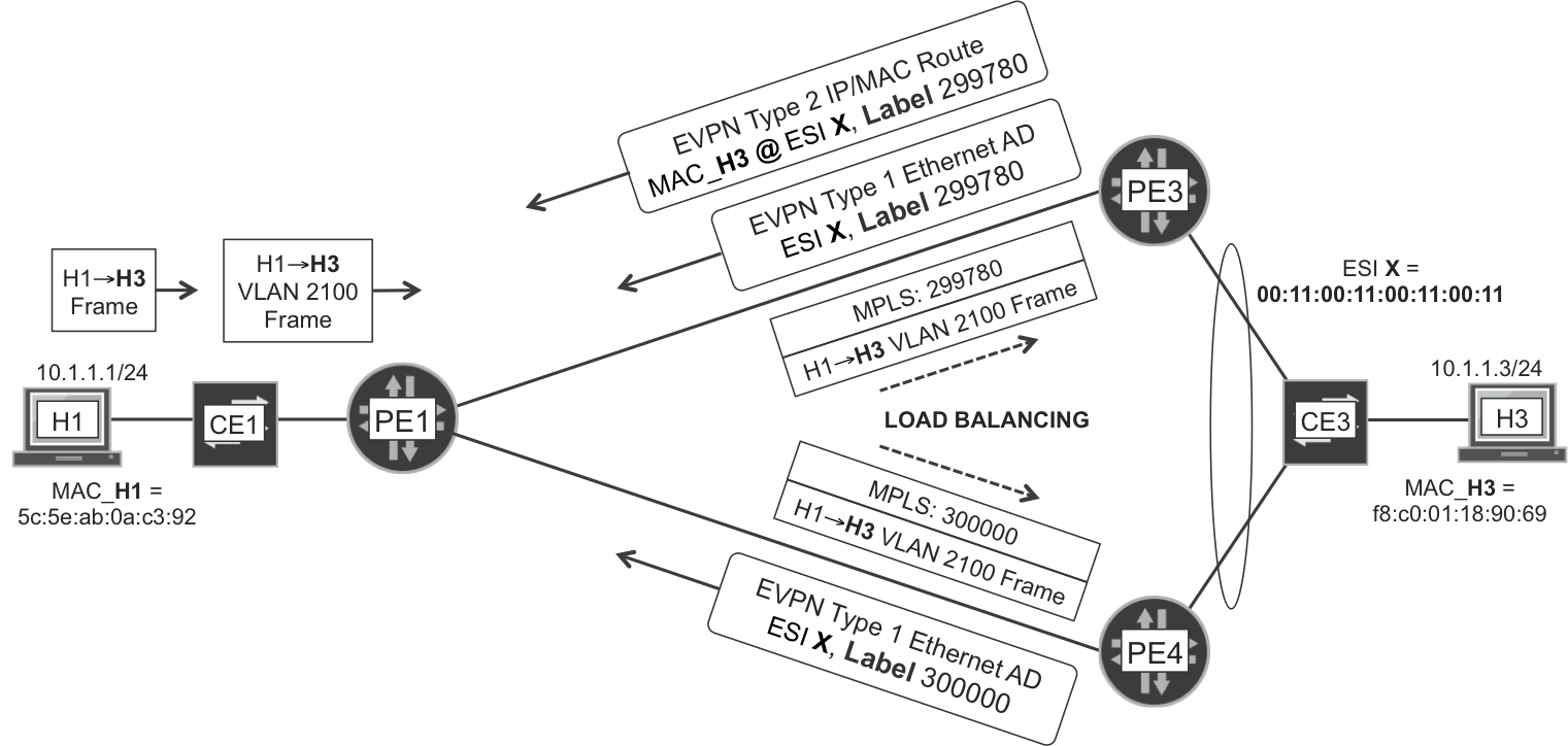
Figure 8-4. EVPN—Aliasing in all-active multihoming
Note
In Figure 8-4, PE3 advertises the same values for the MAC label and for the aliasing label. This is valid but not mandatory. PE3 might have also advertised different values. Conversely, the split horizon label must be different.
There is one additional advantage of using Ethernet AD routes. Imagine that PE3 is advertising 1,000 MAC/IP routes for ESI 00:11:00:11:00:11:00:11:00:11, and its link to CE3 fails or LACP times-out. In this case, by withdrawing the Ethernet AD routes (before withdrawing 1,000 MAC/IP routes), PE3 signals to PE1 that it must flush or update the 1,000 MAC addresses in its bridge table. This speeds up convergence. Furthermore, the single per-ESI Ethernet AD route is very helpful when there is a large number of EVIs.
EVPN all-active—split horizon label
The H1→H3 flow is known unicast, because PE3 has previously learned and advertised H3’s MAC. But, what about BUM traffic? The answer depends on whether the traffic is inbound or outbound with respect to the multihomed ES.
Let’s begin with inbound frames. By virtue of IR, PE1 sends the following:
-
One copy to PE3, after pushing the label that PE3 advertised in its Inclusive Multicast route for [EVPN-A, VLAN 2100]
-
One copy to PE4, after pushing the label that PE4 advertised in its Inclusive Multicast route for [EVPN-A, VLAN 2100]
If both PE3 and PE4 forward the frame to CE3, the end result would be frame duplication toward H3; which is quite undesirable. For this reason, there is a Designated Forwarder (DF) election between PE3 and PE4. Both PEs execute an algorithm to choose the DF. Although this algorithm is locally executed, it must be deterministic in the sense that both PEs choose the same DF for a given [ES, VLAN] pair.
Note
The algorithm is described in RFC 7432, Section 8.5. A different DF may be elected for each VLAN: this is known as service carving.
In this particular example, PE3 is the DF and it is the only one that forwards inbound BUM traffic from VLAN 2100 toward CE3.
What about outbound BUM frames? CE3 performs hash-based load balancing:
-
If a BUM frame in VLAN 2100 goes from CE3 via PE3, PE3 performs IR toward all the other PEs in the EVPN, including PE4. The mechanism is exactly the same as in single-homed ES. PE4 does not forward the frame back to CE3, because it is not the DF.
-
If a BUM frame in VLAN 2100 goes from CE3 via PE4, the mechanism is slightly different because PE4 is not the DF. Although PE4 sends the frame to PE1 and PE2 using the standard IR mechanism, it also sends the frame to PE3 in a very special manner. Indeed, before pushing PE3’s Inclusive Multicast label for VLAN 2100 (see label 299856 in Figure 8-2), PE4 pushes at the bottom of the stack the split horizon label previously advertised by PE3 (Example 8-14, line 23).
When PE3 receives a MPLS-labeled BUM frame from PE4, it first pops the Inclusive Multicast label and maps the frame to [EVPN-A, VLAN 2100]. Then, PE3 looks at the next label and sees the split horizon label that it had previously announced. The key role of the Split Horizon label is to prevent L2 loops: PE3 realizes that the frame comes from ES 00:11:00:11:00:11:00:11:00:11, so it does not forward the frame back to CE3.
But why does PE4 send the frame to PE3 in the first place? Because PE3 might have other local Ethernet Segments to which the frame must be flooded.
EVPN virtual gateway
Setting the same IRB IP+MAC across PEs—for a specific [EVI, VLAN] pair—is enough to achieve all-active load balancing as long as every PE has such an IRB interface. Now, let’s consider an all-active topology in which CE1 is multihomed to PE1 and PE2, whereas CE3 is multihomed to PE3 and PE4. By combining the concepts illustrated in Figure 8-3 and Figure 8-4 for known unicast, you can infer the following:
-
CE1 applies a local hash to distribute outbound H1→H4 frames between its two LAG member interfaces, toward PE1 or PE2, respectively.
-
PE1 (or PE2) receives the packets on its local
irb.2100interface, strips the L2 header, performs an L3 lookup that yields output interfaceirb.2200, pushes a new L2 header, and then tunnels the frame toward PE3 or PE4. The frame is encapsulated under a service MPLS label, which can be either a MAC label or an aliasing label.
But, what if PE1 and PE2 do not have a local IRB interface? In this case, they need to bridge the frame in the context of bridge domain BR-2100 toward the remote IRB, which is in PE3 or PE4. Is there all-active load-balancing from the ingress PE to the two egress PEs? Not really: the ingress PE chooses either PE3 or PE4 because there is no aliasing for the IRB (irb.2100) MAC. Unless you dynamically associate an ESI to the IRB interface: in this case, all-active load-balancing is possible. This virtual gateway functionality is implemented with EVPN Type 1 (Ethernet Segment AD), the details for which are beyond the scope of this book. As of this writing, the Virtual Gateway functionality is implemented in Junos for EVPN with VXLAN transport.
Ethernet VPN with VXLAN Transport
Ethernet VPN is a powerful technology that supports several encapsulation types. VXLAN is one of the available transport options in those typically small-scale and medium-scale data centers whose network does not support (or is not configured for) the transport of MPLS packets.
Data Center Challenges
Although Chapter 10 discusses data center challenges and architectures in greater detail, let’s do a very brief introduction of the use case for VXLAN here.
Data center transport challenge
Data centers are growing exponentially in terms of traffic, services, and geographical distribution. With its many limitations—flooding, L2 loops, and so on—a legacy L2 underlay is no longer an acceptable option. What are the options to build a scalable transport overlay?
In the early 2000s, MPLS was considered to be a pure service provider (SP) (carrier) technology. This has changed now: MPLS is being progressively accepted and deployed as a powerful technology for Data Center Interconnection (DCI) at the WAN edge.
What about server connectivity inside of each data center? As of this writing, not all of the hypervisors support native MPLS yet, so many modern data centers run with an IPv4 overlay. This approach—popularly called IP fabric—supports the transport of servers’ L3 traffic. But that’s not all: it can also transport L2 frames by somehow encapsulating them within an IPv4 packet at the edge of the fabric.
Regardless of the specific flavor chosen, an IPv4 overlay is similar to an IP core network that transparently tunnels customer traffic between edge devices. The edge devices in the data center can be either traditional network PEs (data center gateways) or the networking logic in modern hypervisors, or Top-of-Rack (ToR) switches.
Let’s expand this powerful analogy a bit more:
-
The L2 tunneling overlay is to the data center as an L2 VPN is to an SP.
-
IP is to an IP fabric as IP+MPLS is to an SP core.
Data center multitenancy challenge
Now add the requirement to separate traffic in different virtual instances or tenants. What is a tenant? You can view it as a data center customer or service (it can even be an application). The concept is pretty similar to that of a MPLS VPN in the SP world.
The legacy way to separate tenants in a data center is VLANs. But this approach has many drawbacks, for example:
-
It is a pure L2 technology, with no intelligence to build a scalable overlay.
-
The VLAN ID is a 12-bit value, limiting the number of VLANs (or SVLANs) in a data center to a maximum of 4,095.
Now think of SPs: how was the multitenant problem solved several decades ago? By pushing a (MPLS) label to the packets. This label only lives inside the core and is stripped from the packet before sending it to the customer device.
How is this challenge solved in a data center having an IP overlay? With the very same idea: by encoding something such as a service label over IP. As you can see in Chapter 10’s Figure 10-5, this “something” can be an MPLS label—for example, using MPLS over Generic Routing Encapsulation (GRE) or MPLS over User Datagram Protocol (UDP)—or it can also be a VXLAN Network Identifier (VNI). But what is VXLAN?
VXLAN
Recall from earlier in the chapter that VXLAN stands for Virtual eXtensible Local Area Network. It is defined in RFC 7348 and is basically an L2VPN technology that does not rely on MPLS for transport or service multiplexing. VXLAN was initially proposed with a MAC learning paradigm that was based on the forwarding plane. Because this mechanism does not scale well, control planes came to the rescue and one of them is EVPN.
VXLAN transport tunnels are IP-based. Indeed, VXLAN runs on top of UDP destination port 4789, and its payload is an Ethernet frame—which can be either native or VLAN-tagged. IP tunnels are less optimized than MPLS from the point of view of resiliency and forwarding-plane lookup resources. On the other hand, as of this writing, many intra-data center deployments rely on IP transport—as an evolution from pure legacy L2 VLAN. So let’s explore VXLAN in more detail.
How can we distinguish tenants in the VXLAN world? The VXLAN header has a 24-bit field called segment ID or VXLAN Network Identifier (VNI). And, like an MPLS service label, the VNI acts as a multiplexing field. There is an important implementation difference when comparing a VNI to a service MPLS label: a VNI typically has global significance among the VXLAN Tunnel End Points (VTEPs) in the data center network, whereas a service MPLS label typically has a local significance to the egress PE only.
Figure 8-5 shows a typical architecture with two data centers (one on top, one at the bottom). VXLAN tunnels span inside a single data center, and VXLAN packets are exchanged between VTEPs.
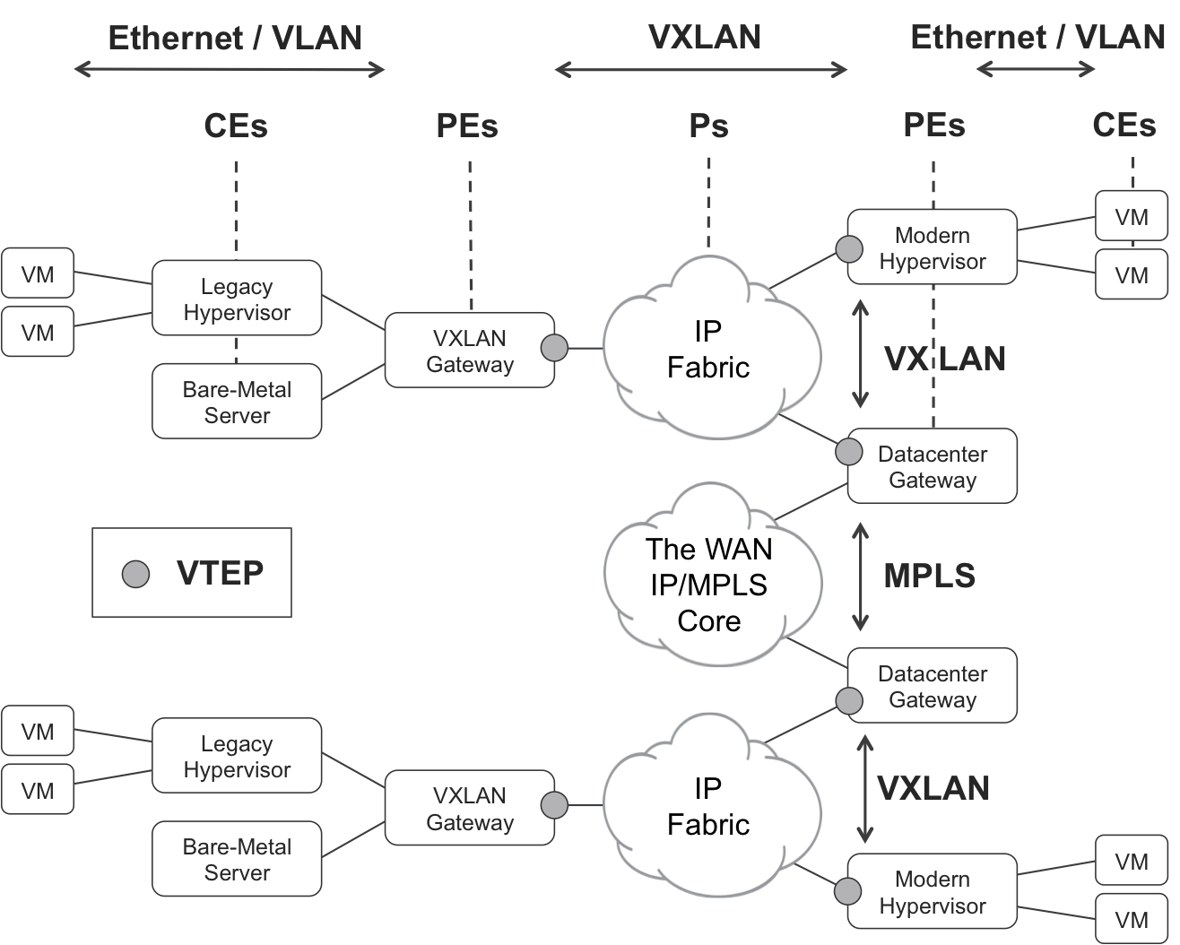
Figure 8-5. VXLAN and VTEPs
Let’s view Figure 8-5 in analogy to MPLS L2 VPN:
-
A VM or a bare-metal server is like a CE. These do not speak VXLAN. They just send and receive untagged or VLAN-tagged Ethernet frames. Traditional hypervisor vSwitches, which are plain VLAN-aware Ethernet bridges, are also considered like (L2) CEs.
-
VTEPs are like PEs. They have (physical or virtual) CE-facing interfaces where they exchange plain native or VLAN-tagged Ethernet frames. And they also have core-facing interfaces where they exchange VXLAN packets.
-
The IP fabric is like an MPLS/IP core. In the same way that MPLS P routers typically do not look at the MPLS service labels, the IP fabric nodes do not look at the packets’ VNI.
There are more than 16 million possible VNI values, overcoming the 4,000 VLAN limitation. Conceptually, though, a VXLAN is closer to an MPLS label than to a VLAN.
You can implement the VTEP function in the software of modern hypervisors and host operating systems. VMs and containers still act as CEs, so they don’t implement VXLAN.
What about bare-metal servers or hypervisors without VXLAN support? You need to connect them as CEs to a VXLAN gateway that performs the VTEP function.
Finally, a data center gateway is a (physical or logical) network device that acts as a VTEP toward the local data center, and as a L2 VPN PE toward the WAN IP/MPLS core.
Nothing prevents you from grouping these functions (hypervisor, VXLAN gateway, and data center gateway) into the same physical device(s).
It’s time to paraphrase RFC 7348.
VXLAN runs over the existing networking infrastructure and provides a means to stretch an L2 network. In short, VXLAN is an L2 overlay scheme on an L3 network. Each overlay is termed a VXLAN segment. Only VMs within the same VXLAN segment can communicate with each other. Each VXLAN segment is identified through a 24-bit segment ID [...] (VNI).
Finishing the analogy, a VXLAN segment is equivalent to a VPN in the MPLS world.
EVPN with VXLAN Transport—Motivation
As of this writing, EVPN VXLAN is described in IETF draft-ietf-bess-evpn-overlay. It is in the standards track, so it might be an RFC by the time you read these lines.
One of the most important use cases of EVPN is DCI: interconnecting several data centers across a MPLS/IP core. This is popularly called the WAN application and it is a natural fit for EVPN MPLS. But EVPN also has a use case within each data center.
How about EVPN VXLAN? If, for whatever reason, a data center does not support the transport of MPLS packets, there are several multitenant IP tunneling options available, and one of them is VXLAN. Strictly speaking, simple VXLAN is already VPN-aware (via the VNI) and has a transport method (IP). VXLAN even implements a native IP Multicast mechanism for VTEP autodiscovery and BUM flooding. Then, what is the point of running EVPN with VXLAN transport?
Using EVPN as the VXLAN’s control plane has many advantages over plain VXLAN:
-
MAC learning implemented by the control plane. VM mobility assisted by the control plane. Unnecessary flooding is reduced.
-
Robust autodiscovery based on BGP, as compared to IP Multicast.
-
Native integration between the L2 and L3 worlds. Strong IRB solution.
-
All-Active multihoming.
-
Arbitrary E-LAN, E-LINE, E-TREE topologies, thanks to RT policies. Use RT policies with care because they may break CE multihoming solutions.
As of this writing, there is one disadvantage of EVPN: plain VXLAN uses IP multicast trees for BUM flooding, which provide a higher forwarding-plane efficiency than IR, the currently implemented mechanism for EVPN VXLAN. That having been said, EVPN is a technology designed to reduce unicast flooding to the minimum. You can also have a look at the Assisted Replication model defined in draft-rabadan-bess-evpn-optimized-ir.
EVPN with VXLAN Transport—Forwarding Plane
Here’s what happens when a bridge domain has a learning vlan-id configured:
-
In both VPLS and EVPN MPLS, the learning VLAN travels within the MPLS-encapsulated frame. Why? An egress PE may allocate the same MPLS label for different bridge domains in a given EVI. To de-multiplex inbound traffic correctly and map it to the right bridge domain, the egress PE expects a VLAN tag.
-
In EVPN VXLAN, by default the VLAN tag is stripped before encapsulating the frame in VXLAN. Why? Every bridge domain has a different VNI, so the VNI acts as a multiplexer. There is typically no need to carry VLAN tags on the core.
You can configure EVPN VXLAN to carry the VLAN tags on the core with two knobs: encapsulate-inner-vlan and decapsulate-accept-inner-vlan.
Example 8-16 shows an H3→H1 frame—an ICMP echo request—encapsulated in VXLAN, assuming that the two previous knobs are configured.
Example 8-16. VXLAN encapsulation (Junos)
Ethernet II, Src: MAC_PE3_ge-0/0/1, Dst: MAC_PE1_ge-0/0/3
Internet Protocol Version 4, Src: 172.16.0.33 , Dst: 172.16.0.11
User Datagram Protocol, Src Port: 55468, Dst Port: 4789
Virtual eXtensible Local Area Network
    Flags: 0x08
        0... .... = Reserved(R): False
        .0.. .... = Reserved(R): False
        ..0. .... = Reserved(R): False
        ...0 .... = Reserved(R): False
        .... 1... = VXLAN Network ID(VNI): Present
        ...0 .... = Reserved(R): False
        ...0 .... = Reserved(R): False
        ...0 .... = Reserved(R): False
    Reserved: 0x000000
    VXLAN Network Identifier (VNI): 5100
    Reserved: 0
Ethernet II, Src: H3 (f8:c0:01:18:90:69), Dst: H1 (5c:5e:ab:0a:c3:92)
802.1Q Virtual LAN, PRI: 0, CFI: 0, ID: 2100
Internet Protocol Version 4, Src: 10.1.1.3, Dst: 10.1.1.1
Internet Control Message Protocol
    Type: 8 (Echo (ping) request)
    Code: 0
You can see the original frame encapsulated in VXLAN, which is in turn encapsulated in UDP. The destination UDP port for VXLAN is 4789.
EVPN with VXLAN Transport—Junos Configuration
EVPN VXLAN was released (in Junos and IOS XR) just before this book’s publication, so the authors did not have time to build multivendor scenarios. However, there was an interoperability proof-of-concept executed and published by the European Advanced Networking Test Center (EANTC).
In the interest of brevity, the following Junos configuration only includes one bridge domain and it has neither IRB nor multihoming. You can refer to Examples Example 8-3 and Example 8-6 for AC and IRB configuration, respectively.
Example 8-17. EVPN VXLAN on a Virtual Switch—PE1 (Junos)
1     routing-instances {
2         EVPN-A {
3             instance-type virtual-switch;
4             vtep-source-interface lo0.0;
5             route-distinguisher 172.16.0.11:2000;
6             vrf-target target:65000:2000;
7             protocols {
8                 evpn {
9                     encapsulation vxlan;
10                    extended-vni-list 5100;
11                }
12            }
13            bridge-domains {
14                BR-2100 {
15                    vlan-id none;
16                    interface ae10.2100;
17                    vxlan {
18                        vni 5100;
19                        ingress-node-replication;
20    }}}}}
Tip
The encapsulate-inner-vlan and decapsulate-accept-inner-vlan knobs are configurable under the vxlan hierarchy (line 17).
The bridge domain’s vlan-id (line 15) is actually the normalization or learning VLAN. The on-the-wire VLAN tag may be different in a per-AC basis, as shown in Example 7-19. And the normalization VLAN is mapped to a VNI. In this case, it is set to none—even if it had a specific value it would be stripped by default.
Multitenancy is possible because a VNI has twice as many bits as a VLAN ID. Imagine 1,000 different tenants, each with its own VLAN ID space (1–4,095). Each [tenant, VLAN] pair can be mapped to a different VNI.
EVPN with VXLAN Transport—Signaling
The signaling is very similar to EVPN with MPLS transport, except for certain details. Here is the Inclusive Multicast route advertised by PE1, one per VNI:
Example 8-18. EVPN VXLAN—Inclusive Multicast route—PE1 (Junos)
1     juniper@PE1> show route advertising-protocol bgp 172.16.0.201
2                  table EVPN-A.evpn.0 match-prefix "3:*" detail
3     [...]
4     * 3:172.16.0.11:2000::5100::172.16.0.11/304 (1 entry, 1 announced)
5      BGP group IBGP type Internal
6          Route Distinguisher: 172.16.0.11:2000
7          Nexthop: Self
8          Localpref: 100
9          AS path: [65000] I
10         Communities: target:65000:2000
11         PMSI: Flags 0x0: Label 5100:
12               Type INGRESS-REPLICATION 172.16.0.11
The NLRI now contains the VNI instead of the VLAN ID. And the label encoded in the PMSI attribute is no longer a MPLS label: it is the VNI!
As shown in the following example, the MAC/IP route’s NLRI also contains the VNI:
Example 8-19. EVPN VXLAN—MAC route—PE1 (Junos)
1     juniper@PE1> show route advertising-protocol bgp 172.16.0.201
2                  table EVPN-A.evpn.0 match-prefix "2:*" detail
3     [...]
4     * 2:172.16.0.11:2000::5100::5c:5e:ab:0a:c3:92/304 (1 entry, 1 announced)
5      BGP group IBGP type Internal
6          Route Distinguisher: 172.16.0.11:2000
7          Nexthop: Self
8          Localpref: 100
9          AS path: [65000] I
10         Communities: target:65000:2000 encapsulation:vxlan
Back to EVPN MPLS, MAC/IP routes included a MPLS label. Here in EVPN VXLAN, the NLRI includes a VNI. As expected!
The VNI is the same for BUM traffic (Example 8-18, lines 4 and 11) and known unicast traffic (Example 8-19, line 4). This is another subtle difference with respect to EVPN MPLS. Another difference is the way in which all-active multihoming works. Since there is no way of using a split-horizon label with VXLAN, the external IP header of the VXLAN packet is inspected in order to determine which PE a BUM frame is arriving from.
Provider Backbone Bridging EVPN
Provider Backbone Bridging (PBB) EVPN is an EVPN variant that can also run either over MPLS or over VXLAN. In a nutshell, PBB EVPN inserts an extra encapsulation between the original Ethernet frame and the transport (MPLS or VXLAN) header. The goal of PBB EVPN is to achieve a higher scalability than native EVPN in the control plane. Let’s see how, after the following analogy.
Introduction to PBB
As of this writing, the Internet IPv4 Full Routing comprises more than a half million prefixes: this is the number of routes that an Internet ASBR typically learns from its transit eBGP peers. Are all of these routes needed? Not really, there is a lot of inefficiency there. However, it could be much worse! Indeed, it is estimated that there are more than ten billion active devices in the Internet of Things (IoT), and many of them have their own public IPv4 address. On average, each single IPv4 public route represents thousands of active hosts. This aggregation—made possible thanks to subnetting and summarization—is one of the reasons why the Internet can scale worldwide. Imagine that every single host resulted in one IPv4 public route: the Internet control plane would be unmanageable!
Now, think about a big data center, with up to millions of MAC addresses, typically corresponding to VMs. Wouldn’t it be great to create MAC group prefixes so that each such prefix could represent thousands of MAC addresses? Unfortunately, this is not implemented in Ethernet. The most significant bytes of a MAC address compose the vendor code of the network interface; so MAC summarization is not an option these days.
How can you scale the L2 service? The best option is to make it L3! It sounds trivial, but it is the best option. On the other hand, some legacy apps require L2 flat connectivity, so the data center infrastructure usually keeps the L2 service in place. What scaling options are there? One of them is PBB, also known as MAC-in-MAC.
PBB is defined in IEEE 802.1ah-2008. It is different from IEEE 802.1ad (Q-in-Q):
-
Q-in-Q or VLAN stacking leaves the original MAC header in place and inserts an extra 4-byte VLAN header—with 3 bytes or 12 bits composing the VLAN tag.
-
PBB encapsulates the original Customer MAC (C-MAC) frame inside a new set of headers including a 24-bit tag called I-SID, and a Backbone MAC (B-MAC) header.
Effectively, this increases the multiplexing space from 4,000 (VLAN) to 16 million (I-SID) values. This achievement is similar to VXLAN’s but, unlike VXLAN, PBB adds a new MAC header. These technologies are very different: VXLAN is L2 over L3, whereas PBB is L2 over L2 (and PBB EVPN is L2 over L2 over L3).
When combined with EVPN, VXLAN and PBB cover two different use cases. VXLAN resolves the challenge of transporting Ethernet frames through an IP fabric; on the other hand, PBB tries to provide a higher scalability by hiding many different C-MACs behind a much more reduced number of B-MACs.
PBB itself does not provide a solution to transport L2 over an IP fabric or an IP/MPLS core. Indeed, PBB EVPN needs to run over VXLAN or MPLS. For this reason, the VXLAN and PBB technologies are not comparable like apples and apples: they fulfill a completely orthogonal purpose.
PBB is a generic technology that has been applied to VPLS, as well: RFC 7041 - Extensions to the Virtual Private LAN Service (VPLS) Provider Edge (PE) Model for Provider Backbone Bridging. PBB VPLS is not covered in this book.
PBB EVPN in a Nutshell
PBB EVPN is described in RFC 7623. This is how it compares to EVPN:
-
There is no concept of B-MAC in EVPN. Each PE advertises all the C-MACs that it locally learns (on its ACs) via EVPN MAC/IP routes. Synchronizing the PEs’ bridge tables via the control plane (BGP) minimizes unicast frame flooding. And customer MAC/IP routes provide a native L2-L3 hook that brings robustness while avoiding undesired behavior like traffic tromboning. On the downside, when C-MACs are in the order of many thousands or even millions, advertising every single C-MAC stresses the control plane—and this is the only motivation for PBB EVPN.
-
PBB EVPN maintains control-plane MAC learning for B-MACs, but it leaves C-MAC address learning exclusively to the forwarding plane (like in VPLS). PEs still need to maintain huge C-MAC bridge tables, and the only benefit brought by PBB EVPN is a reduction in the number of BGP routes. What are the disadvantages?
Warning
PBB EVPN dramatically reduces the control-plane load, at the expense of much more flooding and complexity. As for the nice L3 hooks in EVPN, the PBB layer hides them, so they are no longer available.
PBB EVPN finds its natural application in the WAN (DCI, provider transport, etc.), where the highest number of MAC addresses is expected.
After comparing PBB EVPN to EVPN, let’s now compare PBB EVPN to VPLS. Both technologies rely on the forwarding plane for customer MAC learning, so what are the advantages of PBB EVPN over VPLS? Two specific advantages are all-active multihoming and its better B-MAC flush mechanism.
PBB EVPN Implementations
As of this writing, both Junos and IOS XR support PBB EVPN with MPLS transport.
How about PBB EVPN with VXLAN transport? Neither vendor supports it in generally available (GA) releases as of this writing, but IOS XR had a working prototype at EANTC in 2015.
PBB EVPN in Action
Many examples in this book begin with the configuration and then move on to the signaling and forwarding details. But PBB EVPN is such a tricky technology that it is very difficult to make any sense of the configuration without seeing it in action first.
This book’s PBB EVPN tests achieved Junos and IOS XR interoperability, so the reference topology is the multivendor one in Figure 6-3.
PBB EVPN—IM signaling and BUM traffic forwarding
Figure 8-6 provides a view of how a PBB EVPN service transports an ARP request initially sent from H1 (remember that EVPN route type 3 is Inclusive Multicast). The logic inside PE4 is similar to PE1’s.
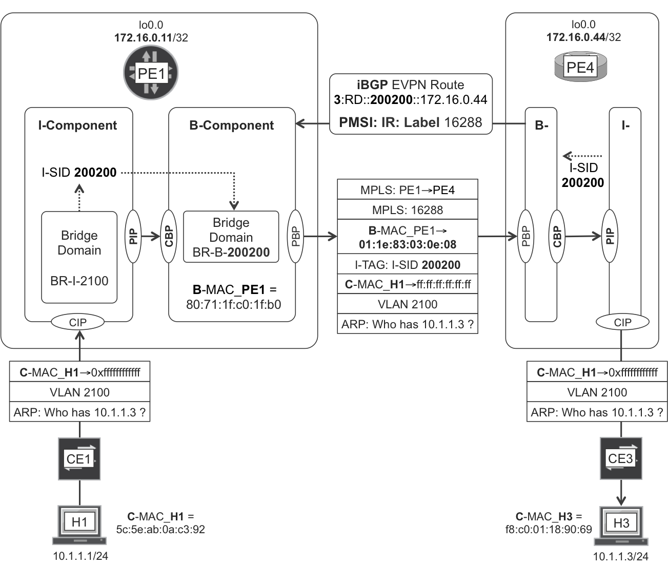
Figure 8-6. PBB EVPN—BUM intra-VLAN bridging
PBB is MAC-in-MAC, and it requires two components on each service endpoint:
- The I-Component (where “I” stands for “Instance”)
- This component is customer facing and bridges frames according to the C-MAC. This C- concept is different from C- in C-VLAN. Indeed, PE1 receives (on its AC) Ethernet frames that can be non-tagged, single-tagged or double-tagged. How PE1 maps these frames to a bridge domain in the I-Component is just virtual switch/bridge domain business as usual (see the VPLS section for more details). In the following examples, the ACs and bridge domains are actually configured with one single
vlan-id, so it is an SVLAN model. Still, from the PBB perspective, the frame’s MAC header is considered to be C-MAC. - The B-Component (where “B” stands for “Backbone”)
- This component is core-facing and it bridges frames according to the B-MAC. The B-MAC is in an outer MAC header as compared to the C-MAC.
The core links in this example are based on Ethernet, so there is yet a third Ethernet header in order to transport the packet from one LER/LSR to its downstream neighbor LSR/LER. This outermost header is not shown in Figure 8-6, but you can find it in Example 8-20, line 1.
The original PBB standard allows for the I-Component and B-Component to be in different devices, but in PBB EVPN, they are assumed to be both in the same PE.
The following interfaces are defined in the PBB model:
-
Customer Instance Port (CIP), at the I-Component and pointing to the ACs
-
Provider Instance Port (PIP), at the I-Component, pointing to the B-Component
-
Customer Backbone Port (CBP), at the B-Component, pointing to the I-Component
-
Provider Backbone Port (PBP), at the B-Component and pointing to the SP core
Let’s assume that each bridge domain only has one (S-)VLAN assigned to it, so there is a 1:1 VLAN:BD mapping. The following N:1 mappings are defined on each PE:
-
N x VLANs to one I-SID
-
N x I-SIDs to one I-Component
-
N x I-Components to one B-Component
-
N x B-Components in one PE; each B-Component is an EVPN Instance.
The N number is arbitrary and it can have a different value for each of these mappings—of course, it can be 1, as well. The I-SID stands for Backbone Service Instance Identifier, and it is the “glue” that binds an I-Component to its peer B-Component.
So there are several levels of N:1 multiplexing. How can de-multiplexing work at all? As you can see in Figure 8-6, the customer frames get some more headers added, including the VLAN tag, the I-SID, and the Inclusive Multicast MPLS label that identifies the B-Component on the egress PE (PE4).
Looking at the B-MAC header in Figure 8-6, the source B-MAC is the local B-MAC assigned to ESI #0 at PE1’s B-Component. This MAC address is locally generated by PE1 in a dynamic manner, and it needs to have a different value on each PE. If PE1 has thousands of C-MACs on ESI #0—remember this is the ESI for all the single-homed and single-active multi-homed sites—all of these C-MACs are hidden behind one single B-MAC. Additionally, it is possible to reuse the same B-MAC in several B-Components on the same PE, because the B-MAC is not a multiplexing field.
How about the destination B-MAC address 01:1e:83:03:0e:08? It is composed of two parts: a fixed 01:1e:83 prefix, and 0x030e08 = 200200, the I-SID value! The following capture shows the Ethernet frame represented earlier in Figure 8-6. As expected, it is encapsulated over PBB-over-MPLS (although, in the capture, over becomes under).
Example 8-20. PBB-over-MPLS encapsulation
1     Ethernet II, Src: MAC_PE1_ge-0/0/4, Dst: MAC_P1_ge-0/0/1
2     MPLS Header, Label: <Transport to-PE4 Label>, Exp: 0, S: 0, TTL: 255
3     MPLS Header, Label: 16288, Exp: 0, S: 1, TTL: 255
4     PW Ethernet Control Word, Sequence Number: 0
5     Ethernet II, Src: 80:71:1f:c0:1f:b0, Dst: 01:1e:83:03:0e:08
6         Type: 802.1ah Provider Backbone Bridge (mac-in-mac) (0x88e7)
7     IEEE 802.1ah
8         I-TAG, I-SID: 200200
9         C-Src: H1_MAC (5c:5e:ab:0a:c3:92)
10        C-Dst: Broadcast (ff:ff:ff:ff:ff:ff)
11        Type: 802.1Q Virtual LAN (0x8100)
12    802.1Q Virtual LAN, PRI: 0, CFI: 0, ID: 2100
13    ARP Request, who is 10.1.1.3, tell 10.1.1.1
Here are the three Ethernet headers:
-
Line 1: Outermost header to take the packet from PE1 to its neighbor P1.
-
Line 5: Source B-MAC dynamically assigned by PE1, and Destination B-MAC computed for BUM in the context of I-SID 200200.
-
Lines 9 through 10: Embedded in the IEEE 802.1ah header, the unicast C-MAC associated to H1 and the broadcast C-MAC address.
When PE4 receives the packet, it first pops the service MPLS label (line 3) and maps the packet to the appropriate B-Component. Then, by looking at the I-SID, PE4 maps the packet to the corresponding I-Component. And the I-Component delivers the customer frame (lines 9 through 13) out of the local ACs. Note that the Source B-MAC is useful for Source C-MAC learning (see Example 8-22).
Complex, isn’t it? Well, there is still known unicast to come, not to mention multihoming. This complexity is the result of one of the most repeated mantras in networking:
Simplicity is never a free lunch. If application developers assume the network is flat, reliable and with zero latency, network designers and engineers need to implement incredibly complex solutions.
In modern times, application development should take the network into account and assume L3 (not L2) connectivity at the very least. A really network-respectful application should also rely on intelligent transport mechanisms that are load-balancing aware. Paraphrasing a blog post from Ivan Pepelnjak on ipspace.net:
In a world with scale-out applications, you don’t need fancy combinations of routing, bridging, and whatever else; you just need fast L3 transport between endpoints.
In a world with really modern applications, a solution such as PBB EVPN should not be needed.
PBB EVPN—B-MAC signaling and known unicast traffic forwarding
Figure 8-7 illustrates how a PBB EVPN service transports the unicast ARP reply from H3 to H1. This is a known unicast packet because of the following:
-
PE4’s I-Component already learned H1’s C-MAC address on its forwarding plane.
-
PE4’s B-Component already learned PE1’s B-MAC address on its control plane.
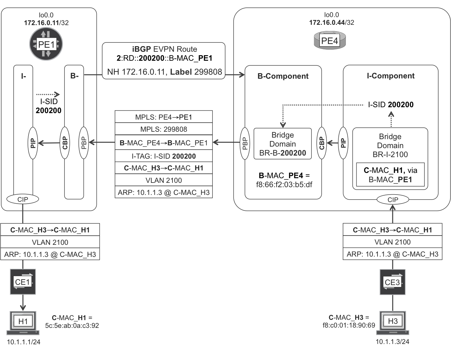
Figure 8-7. PBB EVPN—known unicast intra-VLAN bridging
As you can see, the C_MAC_H1 to B_MAC_PE1 mapping is held at PE4’s I-Component. It is the result of a more-complex-than-usual MAC learning process that was triggered by H1’s ARP request in Figure 8-6. PE4 created this state while processing and removing the ARP request’s B-MAC and I-TAG headers (Example 8-20).
Note
Remember that EVPN Type 2 is MAC/IP. In this case, it is B-MAC.
PBB EVPN Configuration
Now that we can spell PBB EVPN, let’s see an interoperable configuration example.
PBB EVPN—Junos configuration
The AC is configured as is shown in Example 7-9, lines 1 through 8 (just replace 2010 with 2100). Example 8-21 shows a PBB EVPN configuration with just one VLAN and one I-SID.
Example 8-21. PBB EVPN configuration—PE1 (Junos)
1     # I-COMPONENT
2
3     interfaces {
4         pip0 {
5             unit 2000 {
6                 family bridge {
7                     interface-mode trunk;
8                     bridge-domain-type svlan;
9                     isid-list all-service-groups;
10    }}}}
11    routing-instances {
12        EVPN-I-COMPONENT-A {
13            instance-type virtual-switch;
14            interface pip0.2000;
15            bridge-domains {
16                BR-I-2100 {
17                    vlan-id 2100;
18                    interface ge-2/0/1.2100;
19                }
20            }
21            pbb-options {
22                peer-instance EVPN-B-COMPONENT-A;
23            }
24            service-groups {
25                SG-A {
26                    service-type elan;
27                    pbb-service-options {
28                        isid 200200 vlan-id-list 2100;
29    }}}}}
30
31    # B-COMPONENT
32
33    interfaces {
34        cbp0 {
35            unit 2000 {
36                family bridge {
37                    interface-mode trunk;
38                    bridge-domain-type bvlan;
39                    isid-list all;
40    }}}}
41    routing-instances {
42        EVPN-B-COMPONENT-A {
43            instance-type virtual-switch;
44            interface cbp0.2000;
45            route-distinguisher 172.16.0.11:2000;
46            vrf-target target:65000:2000;
47            protocols {
48                evpn {
49                    control-word;
50                    pbb-evpn-core;
51                    extended-isid-list 200200;
52                }
53            }
54            bridge-domains {
55                BR-B-200200 {
56                    vlan-id 1234;
57                    isid-list 200200;
58                    vlan-id-scope-local;
59    }}}}
As shown in Figure 8-6 and Figure 8-7 the PIP (lines 3 through 10) and CBP (lines 33 through 40) interconnect the I-Component to the B-Component, respectively. The actual I-to-B mapping is performed on line 22. VLAN 2100 is mapped to I-SID 200200 on line 28. And I-SID 200200 is mapped to the B-Component on lines 51 and 57.
As for the B-Component bridge domain’s VLAN ID (line 56), it must be set, but its value is not very relevant, because it is never sent on the wire.
Note
The B-Component is an EVPN-capable instance but the I-Component is not.
Example 8-22 shows the result of the configuration.
Example 8-22. PBB EVPN—MAC table—PE1 (Junos)
1     juniper@PE1> show brige mac-table
2
3     MAC flags       (D -dynamic MAC, C -Control MAC)
4
5     Routing instance : EVPN-B-COMPONENT-A
6      Bridging domain : BR-B-200200, VLAN : 1234
7        MAC                 MAC      Logical     NH     RTR
8        address             flags    interface   Index  ID
9        01:1e:83:03:0e:08   DC                   1048575 0
10       f8:66:f2:03:b5:df   DC                   1048576 1048576
11
12    Routing instance : EVPN-I-COMPONENT-A
13     Bridging domain : BR-I-2100, ISID : 200200, VLAN : 2100
14       MAC                 MAC     Logical         Remote
15       address             flags   interface       BEB address
16       5c:5e:ab:0a:c3:92   D       ge-2/0/1.2100
17       f8:c0:01:18:90:69   D       rbeb.32768      f8:66:f2:03:b5:df
By looking carefully at Figure 8-6 and Figure 8-7, you can identify all of the MAC addresses displayed in the previous example:
-
Line 9: Multicast B-MAC address used for BUM in the context of I-SID 200200
-
Line 10: B-MAC address locally assigned by PE4
-
Lines 16 and 17: H1’s and H3’s C-MAC addresses, respectively
The Remote BEB address column (BEB stands for Backbone Edge Bridge) shows, from the perspective of PE1, how H3’s C-MAC is mapped to PE4’s B-MAC. This mapping allows PE1 to successfully process unicast frames destined to H3.
PBB EVPN—IOS XR configuration
IOS XR implicitly creates the PIP and CBP interfaces, so the configuration is shorter:
Example 8-23. PBB EVPN configuration—PE4 (IOS XR)
1     # I-COMPONENT
2
3     interface GigabitEthernet0/0/0/3.2100 l2transport
4      encapsulation dot1q 2100
5     !
6     l2vpn
7      bridge group I-COMPONENTS
8       bridge-domain BR-I-2100
9        interface GigabitEthernet0/0/0/3.2100
10       !
11       pbb edge i-sid 200200 core-bridge BR-B-200200
12    !
13
14    # B-COMPONENT
15
16     bridge group B-COMPONENTS
17      bridge-domain BR-B-200200
18       pbb core
19        evpn evi 2000
20    !
The I-SID clearly acts as a glue from the I-Component to the B-Component (line 11). Where are the EVPN instance’s RD and RT? They are automatically calculated from evpn evi 2000 (line 19):
-
The RD is calculated as <Router ID>:<EVI>, so it is 172.16.0.44:2000.
-
The RT is calculated as <AS>:<EVI>, so it is 65000:2000.
PBB EVPN Signaling
PBB EVPN and EVPN signaling are very similar, but not identical. Here are some differences.
First, PBB EVPN signals B-MACs, whereas EVPN signals C-MACs. Obvious!
There is no L3 hook on the B-Component, so PBB EVPN’s Type 2 routes are only MAC—and not IP/MAC—routes. The NLRI contains the I-SID instead of the VLAN (see the NLRI format shown in Example 8-5 and replace 2100 with 200200).
The trickier difference comes with all-active multihoming. In EVPN, all the ACs connected to the same Ethernet Segment are identified with a common ESI. In PBB EVPN, the implementation is very different. Let’s see it in detail.
First, the administrator or external software manually configures the ES’s B-MAC address. For example, in Junos: set interfaces ae10 esi source-bmac 00:11:22:33:44:55. The ACs connected to a given all-active ES must all have the same B-MAC address, regardless of which PE they are on. So, taking as a reference the topology in Figure 8-1, PE3 and PE4 both have the same B-MAC value configured on the right-facing LAG. The EVPN MAC route looks like the following example:
Example 8-24. EVPN Type 2 MAC route: non-zero ESI—PE3 (Junos)
juniper@PE3> show route advertising-protocol bgp 172.16.0.201
             evpn-mac-address 00:11:22:33:44:55 detail

EVPN-B-COMPONENT-A.evpn.0: [...]
* 2:172.16.0.33:2000::200200::00:11:22:33:44:55/304 (1 entry, ...)
     Route Label: 300776
     ESI: ff:ff:ff:ff:ff:ff:ff:ff:ff:ff
     Communities: target:65000:2000
[...]
Regardless of the configured ESI, the B-MAC route has the ESI attribute set to the all-ones binary value. The key is the B-MAC, which must match on all the PEs connected to a given all-active Ethernet Segment.
There are no Ethernet AD (Type 1) routes in PBB EVPN, simply because there is no need for aliasing. Both PE3 and PE4 advertise the single B-MAC associated to a given ES in a permanent manner (there is no B-MAC aging), so the ingress PEs just need to look up the MPLS label that the egress PEs are advertising for that single B-MAC.
Ethernet Segment (Type 4) routes are present in both EVPN and PBB EVPN, as they are needed for the BUM DF election in all-active ES.