
Chapter 7. Virtual Private LAN Service
Using a rough analogy, you can view a Virtual Private LAN Service (VPLS) instance like a Layer 2 (L2) VRF. Following are two important differences with respect to L3 VRFs:
-
A real (L3) VRF provides virtualized routing, and VPLS provides virtualized switching.
-
PEs advertise L3 (e.g., IP VPN) routes, but they do not advertise VPLS MAC routes to remote PEs.
VPLS just provides Multipoint-to-Multipoint (MP2MP) L2 connectivity between sites; MAC learning is performed in the forwarding plane—unlike IP routes, which are advertised in the control plane. It is very likely that in the following years Ethernet VPN (EVPN) takes over VPLS progressively, but as of this writing, the installed base of VPLS is big, so it deserves its own chapter.
Introduction to VPLS
VPLS is a virtual LAN switching instance with two types of interfaces: traditional Attachment Circuits (ACs) and Pseudowires (PWs). VPLS is a natural extension of Virtual Private Wire Service (VPWS). In a nutshell, here are differences:
-
VPWS can support many L2 technologies; VPLS supports only Ethernet.
-
VPWS is Point-to-Point (P2P), and VPLS is truly MP2MP. Actually, the topology can be quite arbitrary (full-mesh E-LAN, hub-and-spoke E-TREE, etc.) because both the usage of RTs in BGP VPLS and the manual definition of targeted neighbors in LDP VPLS provide that topological flexibility.
-
VPWS does not perform MAC learning (it is not needed), and VPLS does it in the forwarding plane.
The entire VPLS service behaves like a big switch with distributed MAC learning intelligence implemented on each PE. In the context of a given VPLS instance, a PE can have one or more local ACs, and one or more PWs toward remote PEs.
Note
Remember that all the PWs between the same two PEs can share the same pair (one in each direction) of LSPs, which are also known as Packet-Switched Network (PSN) Tunnels, for transport.
For the moment and for the sake of simplicity, let’s use a VPLS example with one VLAN only. In Figure 7-1, all of the PEs are interconnected with a full mesh of bidirectional P2P PWs: PE1—PE2, PE1—PE3, PE1—PE4, PE2—PE3, PE2—PE4, and PE3—PE4.
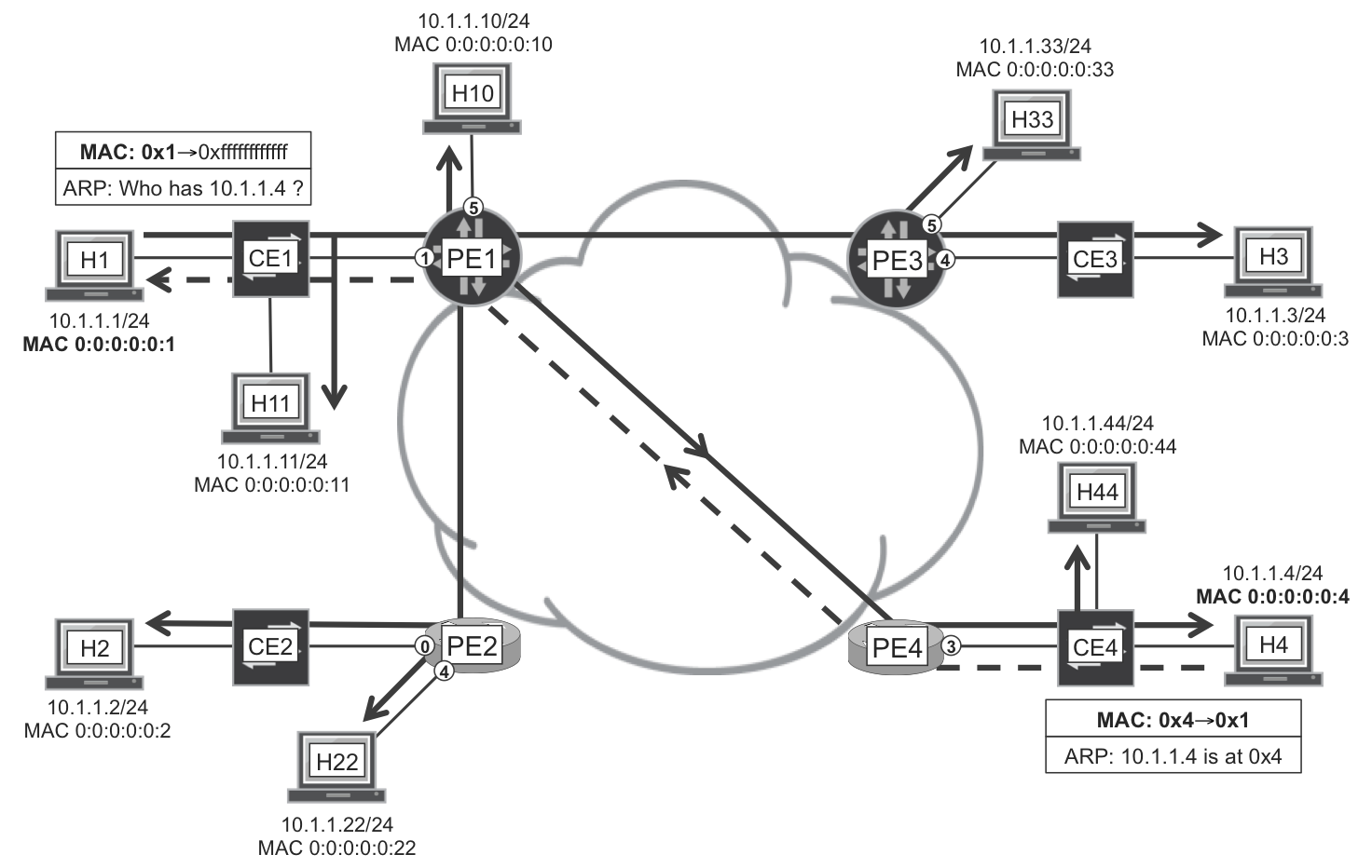
Figure 7-1. VPLS forwarding plane
The service just started, and the very first frame is an ARP request sent by H1. An ARP request is a broadcast frame, which means that its destination MAC address is ff:ff:ff:ff:ff:ff. This is the all-ones or broadcast MAC address, and it represents all the hosts in the bridging domain.
This frame arrives to all the hosts with the MAC addresses unchanged. First, CE1 replicates the frame and sends one copy of the frame to H11 and another copy to PE1. This replication process is known as L2 flooding. Then, PE1 sends one copy to H10—local switching between ACs—and one additional copy over each of the PWs toward PE2, PE3, and PE4. Thus, PE1 sends in total four copies of the original frame. The process continues until all of the hosts receive the ARP request.
During this flooding process, every switching device in the path (the CEs and the VPLS instances on the PEs) also inspects the source MAC address of the frame. In this way, they learn on which interface, or on which PW, the unicast MAC address 00:00:00:00:00:01 can be reached: PE1 learns that MAC 0x1 is reachable over its interface to CE1, and PE4 learns that MAC 0x1 is reachable over its PW to PE1. This process is one of the essential functions of a bridge, and it is known as MAC learning. As a result of MAC learning, bridges populate a MAC table in which they keep track of the interface (or PW) where each unicast MAC is reachable.
When H4 replies to the ARP request, it does so with a unicast Ethernet frame. Its destination MAC address is 0x1, which has already been learned by the network. CE4 knows that it must send this frame on its port toward PE4; in turn, PE4 sends it only over the PW to PE1; and so on. Because the destination MAC address (0x1) has already been learned, the frame is classified as known unicast: it is not replicated and it is forwarded point-to-point until it reaches the destination host H1. In parallel, all the bridges in the path (CE4, PE4, PE1, and CE1) learn the MAC address of H4, 00:00:00:00:00:04.
Figure 7-1 represents a bridge domain, often called a broadcast domain: a broadcast frame is flooded to all the elements in the domain. According to its destination MAC address, a frame can be classified as follows:
-
Broadcast frames have destination MAC address ff:ff:ff:ff:ff:ff.
-
Multicast frames have a destination MAC address whose first octet has its last bit set to one—for example, 01:00:5e:11:22:33 (see Chapter 4) or ff:ff:ff:ff:ff:ff. Strictly speaking, broadcast is a specific case of multicast.
-
Unicast frames have a destination MAC address whose first octet has its last bit set to zero.
What packets are not flooded in a broadcast domain? Unicast frames whose destination MAC address is known—that is, the address is present in the MAC tables—are forwarded point-to-point to the destination host. All of the other frames are flooded, and these are collectively referred to as BUM, or Broadcast, Unknown unicast, and Multicast.
Bridges keep an idle timer for each of the MAC table (cache) entries. If, for a certain amount of time (typically minutes), there is no traffic from a given source MAC address, that particular MAC entry expires and is deleted from the table. Later, if the bridge needs to forward a frame destined to that MAC address, the frame is flooded: known unicast became unknown unicast! So, the known/unknown characteristic of L2 unicast frames depends on the actual traffic patterns.
Then what is the function of VPLS? Simply put, it interconnects the different sites, acting as a “glue” that binds together the PWs and the ACs in a distributed bridge domain. You already saw how PWs are signaled and how traffic is forwarded in a PW. VPLS relies exactly on the same BGP or LDP mechanisms, so this section is shorter.
A very important aspect of VPLS implementation is split horizon. A frame received on a PW is never sent back on the same PW: this is an elementary property of Ethernet bridges. In addition, by default, a frame received on a PW is not forwarded on any other PW, either. Without this precaution, L2 loops would be easily created.
Note
You can tactically change this default behavior in some cases (such as Hierarchical VPLS, discussed later in this chapter).
VPLS Signaled with BGP
BGP VPLS has many points in common with BGP VPWS.
BGP VPLS Configuration
In Junos, you can configure VPLS with two different routing instance types: vpls and virtual-switch. The pros and cons of each approach will be discussed in the context of LDP VPLS. Example 7-1 shows the configuration of a vpls instance at Junos PE1.
Example 7-1. BGP VPLS configuration—PE1 (Junos)
1     interfaces {
2         ge-2/0/1 {
3             flexible-vlan-tagging;
4             encapsulation flexible-ethernet-services;
5             unit 2010 {
6                 encapsulation vlan-vpls;
7                 vlan-id 2010;
8     }}}
9     routing-instances {
10        VPLS-A {
11            instance-type vpls;
12            vlan-id 2010;
13            interface ge-2/0/1.2010;
14            route-distinguisher 172.16.0.11:2010;
15            vrf-target target:65000:2010;
16            protocols {
17                vpls {
18                    control-word;
19                    interface ge-2/0/1.2010;
20                    no-tunnel-services;
21                    site CE1-A {
22                        site-identifier 1;
23                        interface ge-2/0/1.2010;
24    }}}}}
This VPLS instance just has one AC, but it could have several ACs, as is demonstrated in Figure 7-1. How many PWs does it have? Any number, starting from zero. Unlike LDP VPLS, in BGP VPLS, PWs are not explicitly configured and they are not explicitly signaled, either. As you saw in Chapter 6, there is an autodiscovery mechanism relying on CE numbering and label blocks.
For the configuration, you can refer to the explanations between Examples Example 6-3 and Example 6-4. In Example 7-1, a single VLAN tag is specified in the AC, but it could be two (or none), as well.
Line 20 (no-tunnel-services) is optional but recommended for VPLS. It is further explained after Example 7-4.
As for the MTU, Junos does not take it into account in BGP VPLS implementation, but IOS XR does. The only way to achieve interoperability is to configure IOS XR to ignore the MTU mismatch. Example 7-2 shows the configuration at IOS XR PE4.
Example 7-2. BGP VPLS configuration—PE4 (IOS XR)
1     interface GigabitEthernet0/0/0/3.2010 l2transport
2      encapsulation dot1q 2010
3     !
4     l2vpn
5      ignore-mtu-mismatch-ad
6      bridge-group myVPLS
7       bridge-domain VPLS-A
8        interface GigabitEthernet0/0/0/3.2010
9        !
10       vfi CE4-A
11        vpn-id 1234567
12        autodiscovery bgp
13         rd 172.16.0.44:2010
14         route-target 65000:2010
15         signaling-protocol bgp
16         ve-id 4
17         control-word
18    !
In line 10, VFI stands for Virtual Forwarding Instance. In line 16, VE stands for VPLS Edge. In Junos terminology, a VE is a site: a collection of ACs identified by a number (Example 7-1, line 22; and Example 7-2, line 16) that is globally unique in the context of the VPLS.
BGP VPLS Signaling
A very important advantage of BGP VPLS over LDP VPLS is autodiscovery. There is no need to manually specify the remote PEs because RTs dynamically do the trick.
RTs make it possible to build topologies different from a full mesh, exactly like in L3VPN. Although you can achieve the same level of control in LDP VPLS by manually configuring the desired PW topology, using RTs is more dynamic and efficient.
Let’s assume a single-homing topology with the following connections: CE1—PE1, CE2—PE2, CE3—PE3, and CE4—PE4.
The signaling of BGP VPLS is very similar to BGP VPWS. Indeed, it is the same NLRI. This is the autodiscovery route advertised by PE1 for VPLS-A’s site CE1-A.
Example 7-3. L2VPN route advertised for a VPLS service—PE1 (Junos)
juniper@PE1> show route advertising-protocol bgp 172.16.0.201
             table VPLS-A.l2vpn.0 detail

VPLS-A.l2vpn.0: 4 destinations, 7 routes (4 active, ...)
*  172.16.0.11:2010:1:1/96 (1 entry, 1 announced)
 BGP group iBGP-RR type Internal
     Route Distinguisher: 172.16.0.11:2010
     Label-base: 2049, range: 8, offset: 1
     Nexthop: Self
     Flags: Nexthop Change
     Localpref: 100
     AS path: [65000] I
     Communities: target:65000:2010
                  Layer2-info: encaps: VPLS, control flags:[0x2]
                               Control-Word, mtu: 0
                               site preference: 100
Here are the differences between the routes for BGP VPWS and BGP VPLS:
-
The encapsulation signaled in the Layer2 Info community is VPLS for BGP VPLS, versus Ethernet or VLAN for BGP VPWS.
-
There is no Status Vector in BGP VPLS. In BGP VPWS, each local AC is linked to a remote AC in a one-to-one basis, composing a collection of P2P services that could be represented with a vector. In BGP VPLS, any local AC can communicate to any remote AC: this is a communication matrix, not a vector. The decision is not to include the vector in the BGP VPLS NLRI.
The BGP L2VPN NLRI already allocates a label block, so it is prepared for multisite.
Example 7-4. PWs in BGP VPLS instance—PE1 (Junos)
juniper@PE1> show vpls connections instance VPLS-A
             table VPLS-A.l2vpn.0 detail

Instance: VPLS-A
 Local site: CE1-A (1)
  connection-site   Type  St     # Up trans
  2                 rmt   Up     1
   Remote PE: 172.16.0.22, Negotiated control-word: Yes (Null)
    Incoming label: 2050, Outgoing label: 24000
    Local interface: lsi.1048834, Status: Up, Encapsulation: VPLS
  3                 rmt   Up     1
   Remote PE: 172.16.0.33, Negotiated control-word: Yes (Null)
    Incoming label: 2051, Outgoing label: 800256
    Local interface: lsi.1048832, Status: Up, Encapsulation: VPLS
  4                 rmt   Up     1
   Remote PE: 172.16.0.44, Negotiated control-word: Yes (Null)
    Incoming label: 2052, Outgoing label: 24000
    Local interface: lsi.1048833, Status: Up, Encapsulation: VPLS
Here is what each service MPLS label signifies when PE1 receives them:
- 2049
- The labeled frame is coming from site 1, so it must be dropped because site 1 is local to PE1.
- 2050
- The labeled frame is coming from site 2, and therefore on the PW from PE2.
- 2051
- The labeled frame is coming from site 3, and therefore on the PW from PE3.
- 2052
- The labeled frame is coming from site 4, and therefore on the PW from PE4.
Note
Knowing which PW each frame is received on is essential to perform MAC learning and to avoid flooding of known unicast traffic.
After its MPLS labels are removed, the L2 frame is forwarded according to the destination MAC address and the VPLS instance’s forwarding table.
By default, Junos automatically creates one vt- logical interface per remote site; in other words, one for each value of the incoming service MPLS label. When the egress PE receives a L2VPN packet from the core, it pops the service label and maps the packet to a label-specific vt- interface for MAC learning. If the no-tunnel-services knob is configured, there is a Label Switched Interface (lsi)—instead of a vt- interface—per remote site. The vt- and lsi concepts are discussed in more detail in Chapter 3.
BGP VPLS implements a MAC flush mechanism. When a site goes down, the local PE readvertises the site, this time setting the “F” bit in the Layer2 Info control flags. With the “F” flag, the local PE is telling the remote PEs the following: if you have a MAC entry pointing to me for this site, remove it from your MAC table.
The “F” bit is also used in Active-Backup multihoming architectures like the one discussed around Figure 6-5 for BGP VPWS. In normal conditions, the Designated Forwarder in a given site does not set the “F” bit. On the other hand, non-DF PEs set the “F” bit in order to trigger MAC flush on remote PEs that might have MAC entries pointing to them.
Note
VLAN manipulation techniques for instance-type vpls are very similar to those already discussed for VPWS in Chapter 6.
BGP VPLS—Efficient BUM Replication
Both Junos and IOS XR perform Ingress Replication (IR) by default. Therefore, if PE1 receives a BUM frame from an AC, it creates three copies of the original frame and sends one such copy to each of the remote PEs: PE2, PE3, and PE4. Each copy typically has two MPLS labels (inner service label and outer transport label), except for PHP, and travels through a P2P or MP2P LSP.
As discussed in Chapter 5, IR is not particularly efficient as compared to using P2MP LSPs. If configured to do so, both Junos and IOS XR can flood BUM traffic by using single-labeled RSVP-TE Point-to-Multipoint (P2MP) LSPs. This mechanism was already explored in the context of BGP MVPN, which was formerly known as NG-MVPN. In analogy, VPLS with P2MP LSPs for BUM flooding is sometimes called Next Generation VPLS or NG-VPLS.
As of this writing, both Junos and IOS XR support NG-VPLS with RSVP-TE P2MP LSPs. Neither of the two vendors implement it yet for Multipoint LDP (mLDP).
VPLS with P2MP LSPs—Junos configuration
The principle is the same as in BGP Multicast VPN. With the following configuration, PE1 becomes the root of a P2MP RSVP-TE LSP that it uses for BUM flooding in the context of VPLS-A:
Example 7-5. RSVP-TE P2MP LSPs for BUM transport—PE1 (Junos)
routing-instances {
    VPLS-A {
        provider-tunnel {
            rsvp-te {
                label-switched-path-template {
                    default-template;    # Or a custom template
}}}}}
If you have read Chapter 5, this configuration should look familiar.
VPLS with P2MP LSPs—IOS XR configuration
The following configuration achieves similar results in IOS XR:
Example 7-6. RSVP-TE P2MP LSPs for BUM transport—PE4 (IOS XR)
l2vpn
 bridge group myVPLS
  bridge-domain VPLS-A
   vfi CE4-A
    multicast p2mp
     signaling-protocol bgp
     transport rsvp-te
!
VPLS with P2MP LSPs—signaling
When configured as in the two previous examples, the PE updates its BGP L2VPN autodiscovery routes by adding a Provider Multicast Service Interface (PMSI) attribute:
Example 7-7. PMSI attribute in a BGP L2VPN route—PE1 (Junos)
juniper@PE1> show route advertising-protocol bgp 172.16.0.201
             table VPLS-A.l2vpn.0 detail

VPLS-A.l2vpn.0: 3 destinations, 5 routes (3 active, ...)
*  172.16.0.11:2010:1:1/96 (1 entry, 1 announced)
[...]
    PMSI: Flags 0x0: Label 0:
          RSVP-TE: Session_13[172.16.0.11:0:58496:172.16.0.11]
In multicast terms (see Chapter 5), this is an Inclusive PMSI, so all the remote PEs in VPLS-A become leaves of the P2MP LSP.
The rest of the signaling is exactly the same as described in Chapter 5. The leaf PEs receive RSVP-TE path messages whose P2MP LSP Tunnel IPv4 Session is 172.16.0.11:0:58496:172.16.0.11. This value matches the PMSI attribute and that is how the leaf PE binds the RSVP-TE P2MP sub-LSP to the VPLS-A instance.
Likewise, because all of the RSVP-TE P2MP sub-LSPs belonging to the same LSP share the same P2MP LSP Tunnel IPv4 Session value, a transit LSR advertises the same label for all of these sub-LSPs to the upstream LSR. This is how the transit LSRs act as branching points, achieving efficient replication of BUM frames.
VPLS Signaled with LDP
LDP VPLS has many points in common with LDP VPWS.
LDP VPLS Configuration
As already mentioned, there are two instance types in Junos that support VPLS: VPLS instances and Virtual Switches. Which one is better? There is no simple answer. Let’s begin by looking at a configuration example for each instance type and leave the feature comparison for “VLANs and Learning Domains in VPLS”.
LDP VPLS—Junos VPLS instances
Example 7-8 shows a configuration example in Junos featuring a VPLS instance with just one AC (it could be more than one) and three PWs.
Example 7-8. LDP VPLS with VPLS instance—PE1 (Junos)
1     interfaces {
2         ge-2/0/1 {
3             flexible-vlan-tagging;
4             encapsulation flexible-ethernet-services;
5             unit 2010 {
6                 encapsulation vlan-vpls;
7                 vlan-id 2010;
8     }}}
9     routing-instances {
10        VPLS-B {
11            instance-type vpls;
12            vlan-id 2010;
13            interface ge-2/0/1.2010;
14            protocols {
15                vpls {
16                    no-tunnel-services;
17                    vpls-id 24680;
18                    mtu 1900;
19                    neighbor 172.16.0.22;
20                    neighbor 172.16.0.33;
21                    neighbor 172.16.0.44;
22    }}}}
The vpls-id (line 17) value must match on both endpoints, and it is equivalent to the virtual-circuit-id from Example 6-21. Indeed, it is the value of the Martini FEC’s VC-ID.
LDP VPLS—Junos Virtual Switches
Example 7-9 shows the equivalent configuration on a Virtual Switch instead of a VPLS instance.
Example 7-9. LDP VPLS with Virtual Switch—PE1 (Junos)
1     interfaces {
2         ge-2/0/1 {
3             flexible-vlan-tagging;
4             encapsulation flexible-ethernet-services;
5             unit 2010 {
6                 encapsulation vlan-bridge;
7                 vlan-id 2010;
8     }}}
9     routing-instances {
10        VS-B {
11            instance-type virtual-switch;
12            interface ge-2/0/1.2010;
13            protocols {
14                vpls {
15                    no-tunnel-services;
16                    vpls-id 24680;
17                    mtu 1900;
18                    neighbor 172.16.0.22;
19                    neighbor 172.16.0.33;
20                    neighbor 172.16.0.44;
21                }
22            }
23            bridge-domains {
24                BR-2010 {
25                    vlan-id 2010;
26                    interface ge-2/0/1.2010;
27    }}}}
LDP VPLS—IOS XR configuration
IOS XR has one way to configure LDP VPLS, on a bridge-domain (see Example 7-10).
Example 7-10. LDP VPLS configuration—PE4 (IOS XR)
interface GigabitEthernet0/0/0/3.2010 l2transport
 encapsulation dot1q 2010
!
l2vpn
 brige-group myVPLS
  bridge-domain VPLS-B
   mtu 1900
   interface GigabitEthernet0/0/0/3.2010
   !
   vfi CE4-B
    vpn-id 654321   ! This number is irrelevant (not signaled)
    neighbor 172.16.0.11 pw-id 24680
    neighbor 172.16.0.22 pw-id 24680
    neighbor 172.16.0.33 pw-id 24680
!
LDP VPLS Signaling
LDP VPLS and LDP VPWS signaling are virtually identical, to the point that a PW between PE1 and PE4 may be associated to a LDP VPWS at PE1, and to an LDP VPLS instance at PE4, or vice versa (VPLS at PE1 and VPWS at PE4). Interoperability is perfect and you need only ensure that MTU and encapsulation at both ends of the PW match—the Junos ignore-mtu-mismatch and ignore-encapsulation-mismatch knobs are helpful, too.
Due to the multipoint nature of VPLS, there is no AC:PW 1:1 mapping; that’s why you don’t see the AC in the Example 7-11 (as compared to Example 6-23 for VPWS).
Example 7-11. Established LDP VPLS—Junos and IOS XR
# PE1 (Junos)

juniper@PE1> show vpls connections instance VPLS-B
[...]
Instance: VPLS-B
  VPLS-id: 24680
    Neighbor                  Type  St     # Up trans
    172.16.0.22(vpls-id 24680) rmt   Up     1
      Remote PE: 172.16.0.22, Negotiated control-word: No
      Incoming label: 2305, Outgoing label: 24141
      Negotiated PW status TLV: No
      Local interface: lsi.1049614, Status: Up,
                       Encapsulation: ETHERNET
    172.16.0.33(vpls-id 24680) rmt  Up     1
      Remote PE: 172.16.0.33, Negotiated control-word: No
      Incoming label: 2306, Outgoing label: 2405
      Negotiated PW status TLV: No
      Local interface: lsi.1049615, Status: Up,
                       Encapsulation: ETHERNET
    172.16.0.44(vpls-id 24680) rmt  Up     1
      Remote PE: 172.16.0.44, Negotiated control-word: No
      Incoming label: 2307, Outgoing label: 24367
      Negotiated PW status TLV: No
      Local interface: lsi.1049616, Status: Up,
                       Encapsulation: ETHERNET

# PE4 (IOS XR)

RP/0/0/CPU0:PE4#show l2vpn bridge-domain bd-name VPLS-B
[...]
  List of VFIs:
    VFI CE2-B (up)
      Neighbor 172.16.0.11 pw-id 24680, state: up, [...]
      Neighbor 172.16.0.22 pw-id 24680, state: up, [...]
      Neighbor 172.16.0.33 pw-id 24680, state: up, [...]
Here is what each service MPLS label signifies when PE1 receives a labeled packet:
- 2305
- The labeled frame is coming from PE2, and it is processed at
lsi.1049614. - 2306
- The labeled frame is coming from PE3, and it is processed at
lsi.1049615. - 2307
- The labeled frame is coming from PE4, and it is processed at
lsi.1049616.
As discussed many times before, an alternative to lsi is vt- interfaces. The key, regardless of the choice, is that depending on what PE the frame is coming from, it is processed via a different logical interface inside the router. This is essential for the MAC learning process in Junos.
After its MPLS labels are removed, the L2 frame is forwarded according to the destination MAC address and the VPLS instance’s forwarding table.
The command to show the MAC table associated to a given VPLS service in Junos is show vpls mac-table for VPLS instances, and show bridge mac-table for Virtual Switches, as shown in Example 7-12.
Example 7-12. Virtual Switch MAC table—PE1 (Junos)
juniper@PE1> show bridge mac-table instance VS-B

Routing instance : VS-B
 Bridging domain : BR-2010, VLAN : 2010
   MAC                 MAC      Logical          NH     RTR
   address             flags    interface        Index  ID
   6c:9c:ed:37:8a:df   D        xe-0/0/0.2001
   80:71:1f:c0:e9:00   D        lsi.1049904
During this book’s tests, Junos and IOS XR interoperability was successful.
LDP VPLS—Autodiscovery via BGP
If you look back to BGP VPLS configuration (Example 7-1 and Example 7-2), you can see that the administrator does not need to manually specify the remote PE addresses. The magic of BGP and RTs does the trick.
However, LDP VPLS does not have this autodiscovery capability, and you must manually configure the targeted LDP sessions on both ends of each PW. This is the FEC 128 model, and its name comes from the fact that Martini LDP FEC is #128.
Although for VPWS this does not look like a big issue, in LDP VPLS each instance can have many PWs, and manually configuring all of them is quite an overhead and hard to manage. The solution comes with BGP.
Instead of manually configuring the neighbors like in Example 7-8, Example 7-9, and Example 7-10, it is possible to let BGP autodiscover them. When the endpoints are known, the PEs use targeted LDP to signal the PW. This mixed BGP+LDP solution is commonly called FEC 129, because that FEC type is ultimately signaled in the LDP session. Let’s see how it works.
LDP VPLS—FEC 129—BGP configuration
The same L2VPN address family (AFI=25, SAFI=65) is used as for BGP VPWS/VPLS.
IOS XR works fine with the configuration on Example 6-2. As for Junos, it requires the extra configuration shown here:
Example 7-13. L2VPN address family for FEC 129—PE1 (Junos)
protocols {
    bgp {
        group iBGP-RR {
            family l2vpn {
                auto-discovery-only;
}}}}
LDP VPLS—FEC 129—Junos service configuration
FEC 129 works fine in Junos VPLS instances, and as of this writing it is not implemented on Virtual Switches. To transition to FEC 129, you can take the configuration from Example 7-8, remove the neighbors, delete the vpls-id, and then add the following lines:
Example 7-14. LDP VPLS with FEC 129—PE1 (Junos)
1     routing-instances {
2         VPLS-B {
3             route-distinguisher 172.16.0.11:2010;
4             l2vpn-id l2vpn-id:65000:24680;
5             vrf-target target:65000:2010;
6     }}
LDP VPLS—FEC 129—IOS XR service configuration
To transition to FEC 129, you can take the configuration on Example 7-10, remove the neighbors, and then add the lines shown in Example 7-15.
Example 7-15. LDP VPLS configuration—PE4 (IOS XR)
1     l2vpn
2      brige-group myVPLS
3       bridge-domain VPLS-B
4        vfi CE4-B
5         autodiscovery bgp
6          rd 172.16.0.22:2010
7          route-target 65000:2010
8          signaling-protocol ldp
9           vpls-id 65000:24680
10    !
LDP VPLS—FEC 129 signaling
You might have guessed from Example 7-14 (line 4) and Example 7-15 (line 9) that there is a new BGP community that identifies the PW service and must match on both ends. Let’s have a look at it:
Example 7-16. L2VPN FEC 129 route advertised by PE1 (Junos)
juniper@PE1> show route advertising-protocol bgp 172.16.0.201
             table VPLS-B.l2vpn.0 detail

VPLS-B.l2vpn.0: 4 destinations, 5 routes (4 active, ...)
*  172.16.0.11:2010:172.16.0.11/96 (1 entry, 1 announced)
 BGP group iBGP-RR type Internal
     Route Distinguisher: 172.16.0.11:2001
     Autodiscovery for mesh-group: __ves__
     Nexthop: Self
     Flags: Nexthop Change
     Localpref: 100
     AS path: [65000] I
     Communities: target:65000:2010 l2vpn-id:65000:24680
The route advertised by IOS XR looks similar. Thanks to the two communities, the PEs discover each other in the context of this VPLS service.
Now it’s time to signal the PWs themselves:
Example 7-17. LDP FEC 129 exchanged between Junos and IOS XR
juniper@PE1> show ldp database session 172.16.0.44

Input label database, 172.16.0.11:0--172.16.0.44:0
  Label     Prefix
  24011      FEC129 NoCtrlWord ETHERNET
             000afde8:00006068 ac10002c ac10000b

Output label database, 172.16.0.11:0--172.16.0.44:0
  Label     Prefix
   2305      FEC129 NoCtrlWord ETHERNET
             000afde8:00006068 ac10000b ac10002c
The hexadecimal pattern contains 0x6068 = 24680, which nicely matches the L2VPN ID community value. If you look carefully, you can also see the loopback addresses of PE1 and PE4. This completes the signaling of the PW’s service label.
Like BGP VPLS, FEC 129 brings to LDP VPLS the possibility to have an Active-Backup multihoming mechanism and implements the “F” bit.
As for PW Status TLV, it is not that useful in VPLS, because there is no longer an AC:PW coupling. In general, the redundancy story of VPLS is not very compelling, and that is one of the main reasons why EVPN is gaining traction.
VLANs and Learning Domains in VPLS
In the old days of enterprise LANs, virtual LANs (VLANs) were introduced as a way to segment traffic. The VLAN ID can be interpreted in two different manners: it is a 12-bit tag carried on the wire, and also a bridge domain identifier. What is a bridge (or broadcast) domain? Basically, it is a set of (logical) links and hosts such that an L2 frame sent by one host can reach the other hosts without any L3 routing action. Typically, a bridge domain is a full-mesh E-LAN, but with VPLS it is possible to create other topologies such as a hub-and-spoke E-Tree.
VLANs bring virtualization in the forwarding plane as well as in the control plane, in the sense that a different MAC table is kept for each VLAN. In the same way that one IP route can be present in different VRFs and represent a separate network, the same MAC address can be present in different MAC tables or learning domains.
Note
Although the concepts are not strictly equivalent, for simplicity this book uses the terms “learning domain,” “bridge domain,” and “broadcast domain” interchangeably.
Keeping in mind that the VLAN ID on-the-wire is not necessarily identical to the VLAN ID identifying the bridge domain, let’s see the different options.
For brevity, let’s consider ACs configured with one VLAN tag only. In this case, if a frame has two VLAN tags, only the outer one is taken into account for bridging: the internal tag is left untouched and it’s considered as part of the payload.
Suppose that each PE has four ACs locally attached to the VPLS service:
-
AC-A and AC-B—connected to CE-A and CE-B, respectively—are both configured with VLAN 2010.
-
AC-C—connected to CE-C—is configured with VLAN 2011.
-
AC-D—connected to CE-D—is configured with VLAN 2222.
Each PE has four CEs attached, which adds up to 16 CEs in total.
VLANs 2010, 2011, and 2222 are the on-the-wire VLAN tags. The frames sent and received on the ACs have these values set in the outer (maybe the only) VLAN header.
VPLS in default VLAN mode
The default behavior in both IOS XR VFIs and Junos VPLS instances is the same (Virtual Switches are discussed later). There is only one learning domain associated with the instance, which is VLAN-agnostic. After it receives a frame from an AC, the PE preserves the original VLAN tag(s). If the frame needs to be sent out to one or more PWs, it also travels with the original VLAN tag(s). Here is the result:
-
CE-A can communicate to the local CE-B, and to remote PEs’ CE-A and CE-B.
-
CE-B can communicate to the local CE-A, and to remote PEs’ CE-A and CE-B.
-
CE-C can communicate to the remote PEs’ CE-C.
-
CE-D can communicate to the remote PEs’ CE-D.
If you want all the CEs to communicate to one another, you need to use VLAN translation techniques such as those shown in Example 6-17.
In this default implementation, the VLAN tag is considered as a property of the frame: it does not identify the bridge domain. In Junos, this is achieved when the vlan-id is not set on the VPLS instance (Example 7-8, line 12).
Note
In Junos VPLS instances, it is recommended that you set the vlan-id.
Junos VPLS Instances—Normalized VLAN Mode
Let’s see the implementation when the vlan-id is set to a specific number on a VPLS instance. In this case, the on-the-wire VLAN tag is replaced inside the router with a different value, called the normalized tag. This tag is kept when the frame is flooded or forwarded to a PW.
If you set vlan-id 2222 (for example) on the VPLS instance, the VLAN tags for incoming frames are swapped to the normalized tag: 2222. And the outgoing frames whose VLAN tag is 2222 get their tag swapped to the AC’s on-the-wire VLAN tag. For example, if CE-A sends a BUM frame, it is flooded:
-
To the local CE-B with VLAN tag 2010.
-
To the local CE-C with VLAN tag 2011.
-
To the local CE-D and into the PWs with VLAN tag 2222.
Before the frame is sent out of AC-B and AC-C, it actually has VLAN tag 2222 inside the router, but this tag is swapped as the frame is sent out of the AC.
The end result is a single bridge domain where local switching between the ACs is successful, regardless of whether the on-the-wire VLAN tags match the in-box tag. This ensures communication among all the CEs and is called VLAN normalization, shown in Example 7-18.
Example 7-18. VLAN normalization in a VPLS instance—PE1 (Junos)
interfaces {
    ge-2/0/1 unit 2010 vlan-id 2010;
}
routing-instances {
    VPLS-B vlan-id 2222;
}

juniper@PE1> show interfaces ge-2/0/1.2010 | match vlan-tag
    VLAN-Tag [ 0x8100.2010 ] In(swap .2222) Out(swap .2010)
What about the remote CEs that are reachable via the PWs? The remote PEs’ VPLS instance must know what to do with frames whose VLAN tag is 2222:
-
If it is a Junos VPLS instance with
vlan-id 2222, it works fine. -
If it is a Junos VPLS instance with a different
vlan-id, it does not work. -
If it is an IOS XR VFI or a Junos VPLS instance in the default mode, it works fine if either the AC is configured with on-the-wire tag 2222 or it has a translation rule (
vlan-mapin Junos language) applied that handles the translation from/to the normalized tag 2222 to the AC-specific tag on-the-wire.
Note
It is possible to normalize both SVLAN and CVLAN. In this case, use vlan-tags on the VPLS instance and on the ACs. These values don’t need to match: normalization takes care of the translation!
Junos VPLS Instances—VLAN-Free Mode
Let’s see the implementation when the vlan-id is set to none. In this case, the outer on-the-wire VLAN tag is popped when the frame enters the router. It is pushed when the frame is sent out of the AC.
For example, if CE-A sends a BUM frame, it is flooded:
-
To the local CE-B with VLAN tag 2010.
-
To the local CE-C with VLAN tag 2011.
-
To the local CE-D with VLAN tag 2222.
-
With no VLAN tag into the PWs, unless the CE sent dual-tagged frames, in which case the original inner tag is preserved.
Before the frame is sent out of AC-B, AC-C, and AC-D, it actually has no VLAN tag (unless the original frame was dual-tagged) inside the router. The AC-specific VLAN tag is pushed as the frame is sent out of the AC.
The end result is a single bridge domain where local switching between the ACs is successful, regardless of the on-the-wire VLAN tag value.
What about the remote CEs that are reachable via the PWs? The remote PEs’ VPLS instance must know what to do with tag-less Ethernet frames:
-
If it is a Junos VPLS instance with
vlan-id none, it works fine. -
If it is a Junos VPLS instance with a different
vlan-id <value>, it does not work, unless the original frame sent by the CE was dual-tagged and its inner VLAN tag matched<value>. -
If it is an IOS XR VFI or a Junos VPLS instance in the default mode, either the AC is a physical port with no VLAN tag, or the AC has applied an in-pop out-push translation rule (
vlan-mapin Junos language), such as that shown in Example 6-18, or the original frame sent by the CE was dual-tagged and its inner tag matches the AC’s VLAN ID.
Junos VPLS Instances—VLAN-Aware Mode
Let’s see the implementation when the vlan-id is set to all. In this case, the PE autodetects the VLAN tag of a frame as it enters the router. When an incoming frame has a VLAN tag that does not match any existing bridge domain, Junos creates a new bridge domain for the new (VPLS instance, VLAN tag) pair. Therefore, flooding is VLAN-aware. You can check that by using the command show vpls mac-table, which displays one domain per VLAN with active traffic and MAC entries.
For example, if CE-A sends a BUM frame, it is flooded:
-
To the local CE-B with VLAN tag 2010.
-
With the original VLAN tag 2010 into the PWs.
Let’s go back to the BUM frame sent by CE-A. The remote PEs’ VPLS instance must know what to do with a frame with VLAN ID 2010:
-
If it is a Junos VPLS instance with
vlan-id allorvlan-id 2010, it works fine. -
If it is a Junos VPLS instance with a different
vlan-id <value>, or none, end-to-end connectivity fails. -
If it is an IOS XR VFI or a Junos VPLS instance in the default mode, either the AC is configured with on-the-wire tag 2010, or it has a translation rule (
vlan-mapin Junos language) applied that handles the translation from/to the 2010 tag to the specific AC-specific tag on-the-wire.
Junos Virtual Switches
Virtual Switches have the greatest granularity because they support per-VLAN bridge domains, and these implement automatic normalization. If you look back at Example 7-9, you can define several bridge domains such as BR-2010 in the same Virtual Switch; each bridge domain can have one or more associated ACs.
The scenario becomes even more interesting when the AC on-the-wire VLAN tag is different from the learning VLAN tag. This is VLAN normalization:
Example 7-19. VLAN normalization in a bridge domain—PE1 (Junos)
interfaces {
    ge-2/0/1 unit 2010 vlan-id 2010;
}
routing-instances {
    VS-B {
        bridge-domains {
            BR-2222 {
                vlan-id 2222;
                interface ge-2/0/1.2010;
}}}}

juniper@PE1> show interfaces ge-2/0/1.2010 | match vlan
    VLAN-Tag [ 0x8100.2010 ] In(swap .2222) Out(swap .2010)
    Encapsulation: VLAN-Bridge
The concept is identical to VLAN normalization in VPLS instances, with the advantage that here you can associate one different learning VLAN to each bridge domain in the Virtual Switch.
As you know, a Virtual Switch supports one or more bridge domains, which can be displayed by using the show bridge domain and show bridge mac-table commands.
The end result is similar to a set of VPLS instances in normalized VLAN mode, with several advantages. First, Virtual Switches can use the same set of PWs to transport frames for several feature-rich bridge domains. True, VPLS instances with vlan-id all can also multiplex the PWs and dynamically create per-VLAN bridge domains, but these domains are not feature-rich. But what does feature-rich mean? Each of the bridge domains in a Virtual Switch can have its own normalization VLAN and its own IRB interface. Now, let’s see what IRB stands for.
Integrated Routing and Bridging in VPLS
The Integrated Routing and Bridging (IRB) concept was conceived in enterprise LANs, where so-called L3 switches implement inter-VLAN routing. Every bridge domain or VLAN has a default gateway that is implemented in an IRB interface. Suppose that an L2 switch has four VLANs: 2001 through 2004. Each VLAN spans many access (untagged) and trunk (VLAN-tagged) ports on the switch. A pure L2 switch does not need to have any IP address on the VLANs: it just bridges frames on each domain separately. But that results in four isolated domains.
If you want to interconnect the four VLANs at the L3 level, you can do either of the following:
-
Use a traditional L3 router on-a-stick.
-
Enhance the L2 switch with L3 capabilities so that it becomes an L3 switch.
In the latter case, the L3 switch has four virtual IP interfaces, each linked to one VLAN. These IP interfaces are called IRB in Junos and Bridge Virtual Interface (BVI) in IOS XR. The hosts in each VLAN typically use the IRB/BVI address as the default gateway—Virtual Router Redundancy Protocol (VRRP) is discussed later. The L3 switch performs inter-VLAN routing and also routing between a VLAN and the WAN.
VPLS with IRB/BVI provides an L3 switching service. IRB is especially important in Data Center Interconnect scenarios. As for L2VPN as a Transport, IRB is not that relevant: PWHE is.
IRB Configuration in Junos VPLS Instances
Junos VPLS instances only support one IRB interface. This makes IRB suitable for normalized VLAN Mode (vlan-id <number> or vlan-tags) and for VLAN-free mode (vlan-id none). Example 7-20 shows an IRB configuration.
Example 7-20. IRB on a VPLS Instance—PE1 (Junos)
1     interfaces {
2         irb {
3             unit 2010 {
4                 family inet address 10.1.1.101/24;
5                 mac 00:00:01:00:20:10;
6     }}}
7     routing-instances {
8         VPLS-B {
9             routing-interface irb.2010;
10    }}
Note
The IRB unit ID (line 3) does not need to match the VPLS vlan-id.
Now, the irb.2010 interface is like any L3 interface. It can be either left in the global routing table, or assigned to a VRF (set routing-instances <VRF> interface irb.2010). How is inter-VLAN routing possible? Just take several VPLS instances, each with its own IRB logical interface, and ensure that all these IRB interfaces belong to the same L3 routing instance. The latter can also have L3 WAN interfaces and then our PE becomes a full-blown data center gateway (DC GW).
The MAC address configuration (line 5) is critical. In VPLS, it is important that every host in the domain can send frames to—and receive frames from—the IRB MAC address of every PE in an independent manner. This is guaranteed only if each PE uses a different MAC address on the IRB. Otherwise, a PE can intercept frames packets targeted to (or sourced from) another PE. The MAC address must be unicast, so the last bit of the first octet must be zero. It must also be unique; in the example, it is made of the PE number and the VLAN ID, but you can use any other numbering schemes.
The IRB interface is untagged, and the ACs are typically tagged. Junos automatically handles this discrepancy; not only in VLAN-free mode, but also in normalized VLAN mode. Suppose that PE1 receives on ge-2/0/1.2010 (or on a PW) a frame tagged with VLAN 2010 and with destination MAC address 00:00:01:00:20:10 (or the broadcast address). In that case, PE1 automatically pops the VLAN tag before handing the frame to the IRB. Likewise, when the IRB originates an untagged frame, PE1 pushes the VLAN tag before sending the frame out of the AC (or the PW). However, if the incoming traffic has two VLAN tags and the AC’s configuration has only one VLAN tag, forwarding breaks: Junos IRB relies on the actual traffic matching the AC’s settings.
IRB Configuration in Junos Virtual Switches
One advantage of Virtual Switches over VPLS instances is that it supports one IRB per bridge domain. Example 7-21 shows how to bind an IRB logical interface to a Virtual Switch.
Example 7-21. IRB on a Virtual Switch’s bridge domain—PE1 (Junos)
routing-instances {
    VS-B {
        bridge-domains BR-2010 routing-interface irb.2010;
}}
IRB Configuration in IOS XR
The following example shows the configuration of an IRB (BVI) interface in IOS XR:
Example 7-22. IRB on a bridge domain—PE4 (IOS XR)
interface BVI2010
 ipv4 address 10.1.1.104 255.255.255.0
 mac-address 0000.0400.2010
!
l2vpn
 bridge group myVPLS
  bridge-domain VPLS-B
   routed interface BVI2010
!
This BVI interface is shared by all of the ACs and PWs in the bridge domain VPLS-B, regardless of their VLAN tag. As in Junos IRB, the BVI interface is untagged. But unlike Junos, VLAN tag pop/push for IRB/BVI is not automatic in IOS XR. As a result, any frame destined to the BVI unicast MAC address (or to the broadcast address) from an AC or a PW must be explicitly stripped from any VLAN tags. This is critical for interoperability: it is not only PE4 that must be locally configured with this in mind; the remote PEs—and some of them run Junos—also need to send and receive untagged frames over the PWs they establish with PE4.
Now, if the ACs are VLAN tagged, you need to use the following techniques:
-
Manually stripping VLAN tags from the ACs, such as in Example 6-18, so that the frames arrive untagged to the BVI. This works fine in IOS XR and also in Junos VPLS instances running in legacy mode (no
vlan-idon the instance). -
Junos VPLS instances running in VLAN-free mode (
vlan-id none). This is the recommended approach in Junos for interoperating with IOS XR.
VPLS—IRB Redundancy and Traffic Tromboning
Let’s take the example of a data center with four L2 switches: CE1, CE2, CE3, and CE4. Each CE has different hosts attached, distributed in broadcast domains, as outlined in Figure 7-2.
The topology is single-homed with the following VLAN-tagged links: CE1-PE1, CE2-PE2, CE3-PE3, and CE4-PE4. Every link transports two different VLAN tags (2001 and 2002). Each VLAN is associated to a different broadcast domain in the data center, to a bridge domain (or VPLS instance) at the PEs, and to a different IPv4 subnet (10.1.1.0/24 and 10.1.2.0/24, respectively). More specifically:
-
PE1 and PE3 have two VPLS instances configured with
vlan-id none. The logical ACs withvlan-id2001 and 2002 are attached to the VPLS-1 and VPLS-2 instances, respectively. Each VPLS instance has its own IRB interface: irb.2001 and irb.2002. -
PE2 and PE4 have two bridge domains. The logical ACs with
encapsulation dot1q2001 and 2002 are attached to the VPLS-1 and VPLS-2 instances, respectively. Each VPLS instance has its own IRB interface: BVI2001 and BVI2002.

Figure 7-2. VPLS IRB and traffic tromboning
The IRBs’ primary IPv4 and MAC addresses are unique in the entire data center domain. In other words, each [PE, IRB] pair has a different primary IPv4 address and a different primary MAC address. Why different MAC and IPv4 addresses? Duplicate MAC addresses might result in a segmented bridge domain because a PE would block transit traffic sourced from its own IRB MAC address. And non-unique IPv4 addresses might result in unpredictable ARP resolution.
Note
Thanks to its more powerful control plane, EVPN supports having the same IRB IPv4 and MAC addresses in different PEs. You will see that in Chapter 8.
Now, on each PE, the three IRB/BVI interfaces are all grouped in the same VRF. So, there is one single L3VPN for the entire data center. This makes inter-VLAN routing possible.
Let’s assume that each host has a default gateway configuration pointing to the IPv4 address configured on the closest PE’s irb.<vlan> or BVI<vlan> interface.
H1-A and H4-B are two hosts in the data center. H1-A is connected to CE1 and it belongs to VLAN 2001. H4-B is connected to CE4 and it belongs to VLAN 2002. Packets from H1-A to H4-B are routed by PE1, and packets from H4-B to H1-A are routed by PE4. This results in an asymmetrical routing scheme, but it is perfectly fine.
VPLS and VRRP
The previously described architecture has a couple of issues:
-
First, if the CE1-PE1 uplink fails, the hosts connected to CE1 become isolated.
-
Second, each site must be configured with a different default gateway address. This is not only very complex to manage, it also breaks modern applications such as VM mobility across the data center.
VPLS can solve the first challenge with Active-Backup CE multihoming—because VPLS does not support Active-Active. When multihomed, CE1 has an Active-Backup Link Aggregate Group with two links: one to PE1, and one to PE2.
The second challenge is addressed by VRRP. For each VRRP group—and the common practice is to define one group per bridge domain—all the routers share a common secondary IPv4 address and a common secondary MAC address. But, for each group, only one PE (so-called the VRRP master) has these addresses in an active state on its IRB interface. The VRRP master is the only router in each group that does the following:
-
Periodically sends VRRP hellos sourced from the group MAC address.
-
Sends ARP replies (and gratuitous ARP requests) mapping the group IPv4 address to the group MAC address.
All the hosts in a given VLAN configure the group IPv4 address as their default gateway, and resolve via ARP this IPv4 address to the group MAC address. Back to our example, PE1’s IRB interfaces are VRRP masters on their respective bridge domains. The virtual (MAC, IPv4) addresses for each bridge domain are (00:00:5e:00:01:01, 10.1.1.100) and (00:00:5e:00:01:02, 10.1.2.100), respectively. The VRRP master is elected according to the configured priorities and a tie-breaking mechanism based on the primary IPv4 address numerical value.
Now, what are the challenges of this solution?
First, suppose that there is one more PE that provides connectivity between the data center and the rest of the world (or the rest of the L3VPN). This Gateway PE advertises IPv4 VPN routes that the data center PEs (PE1, PE2, PE3, and PE4) import in their own data center VRF. Now, it’s important that a PE does not become a VRRP master if it does not have the full routing picture. Otherwise, such a PE would attract upstream traffic that it cannot route, which ultimately results in traffic blackholing. One way to handle this is by making the VRRP priority a dynamic value which is automatically decreased if certain routes are missing from the local VRF. Still, this solution is far from clean as compared to the elegant way that EVPN addresses this very same challenge, as you will see soon.
In addition, if the gateway PE needs to send a packet to one of the hosts in the data center, it will send it to one of the data center PEs. Which one? Well, they all advertise the /24 addresses, so one of them will be considered as the best (based on the BGP route-selection process), but it might not necessarily be the PE that is local to the host. This results in suboptimal forwarding that you can fix in two ways: activating the VPLS service at the gateway PE, or replacing VPLS with EVPN.
On a separate note, in VPNs in general and VPLS/EVPN in particular, it is considered a good practice to configure a delay between the time an AC goes up and the time when the control and forwarding planes consider the AC to be active. In this way, you give time for the core protocols to converge before enabling the ACs, reducing the likelihood of traffic blackholes.
Note
As a general rule on interfaces with L2 ACs, set hold-time up (Junos) or carrier-delay up (IOS XR) to at least one minute.
Traffic tromboning
Here is one more issue illustrated in Figure 7-2. H3-A and H3-B are two hosts connected to CE3 and belonging to VLAN 2001 and 2002, respectively. PE1 is the VRRP master for VLAN 2001. If H3-A sends an IP packet to H3-B, it must send it to its default gateway: PE1’s irb.2001.
As a result, H3-A to H3-B inter-VLAN routing follows this path: H3-A→CE3→ PE3→PE1→PE3→CE3→H3-B. Thus, packets originated and destined to the same data center site are actually forwarded via a remote data center site. This phenomenon is called traffic tromboning (inspired by the shape of a trombone) and is also elegantly solved by EVPN.
Hierarchical VPLS
To enhance the scalability or security of a VPLS design, you can implement hierarchical VPLS (H-VPLS) models. Depending on the VPLS signaling protocol, you can deploy three different models:
- LDP signaling
- H-VPLS model based on PWs (VPWS service) initiated on Spoke devices and terminated inside a VPLS instance on Hub devices
- BGP signaling
- H-VPLS based on Route Target (RT) filtering
- BGP signaling
- H-VPLS based on site ID (site-range) filtering
Note
Due to space constraints, this book presents only a short description of each hierarchical VPLS model.
H-VPLS Model with LDP Signaling
VPLS scaling with LDP signaling, as defined in RFC 4762, Section 10, looks at how to minimize the number of required PWs. As discussed earlier in this chapter, VPLS in its typical form requires a full mesh of PWs established between all participating devices. As the network grows, and more and more VPLS Edge (VE) devices are added, the number of required PWs might grow considerably—significantly enough, in fact, that it can cause scaling problems on some low-end VE devices.
The problem is somehow similar to the iBGP session full-mesh problem. In the case of iBGP, to overcome session full-mesh scaling limitation, you can deploy Route Reflectors (very frequently used) or confederations (used sometimes, as well). The basic idea of all these solutions is to break the session full-mesh requirement and allow iBGP neighbors to peer to one another only in a partial-mesh fashion—full mesh is no longer required.
Looking from very high level, you can apply the basic idea introduced to solve iBGP session full-mesh problem to solving the PW full-mesh problem between VPLS edge devices. The significant difference, however, is that the iBGP problem is a pure control-plane one, whereas in LDP-based VPLS, control and forwarding planes are more coupled together.
To relax the requirement for PW full-mesh, the H-VPLS model is defined in RFC 4762, Section 10. There are a couple of variations of the H-VPLS model outlined in the RFC. On the hub side (referenced in RFC as PE-rs, meaning a PE device that can perform global routing and private switching), the variations do not differ—in each of those variations PWs from a spoke device terminate in a VPLS instance on V-hubs.
The basic H-VPLS variation (Section 10.1.3 in the RFC) assumes that the spoke device (referenced in the RFC as PE-r) is not capable of providing bridging capability among multiple interfaces. In this variation, the spoke is only capable of establishing a PW and transporting frames from the local interface (AC) over such PW, and vice versa.
A more advanced H-VPLS variation (Section 10.1.1 in the RFC) and its redundant option (Section 10.2 in the RFC) assumes that you can configure bridging instances on the spokes (referred to MTU-s in the RFC).
The H-VPLS model is conceptually similar to the hierarchical L3VPN model based on PWHE architecture (see Chapter 17). However, there are, of course, some differences that you typically see in H-VPLS architectures:
-
PWs used in the H-VPLS architecture can be terminated on the hub device directly (natively) inside a VPLS instance without the need for ps (Junos) or PW-Ether (IOS XR) auxiliary interfaces. However, the integration of VPLS with the L3 world relies on IRB interfaces, which do not implement the same feature set as PWHE interfaces.
-
Because H-VPLS operates in principle on L2, you can use L2-capable spoke devices to provide local bridging for locally connected CEs. In the PWHE-based H-L3VPN model, traffic between two CEs connected to the same spoke device typically goes via the hub, as only the hub provides L3 (routing) capabilities required to route the traffic between two CEs.
Depending on the configuration of the hub device, L2 forwarding between two spokes with PWs terminated on the same hub can be allowed (classic H-VPLS with spoke-to-spoke forwarding) or prevented (H-VPLS without spoke-to-spoke forwarding, called as well Hub-and-Spoke VPLS).
H-VPLS Models with BGP for Autodiscovery and Signaling
In BGP VPLS, you can deploy two models for hierarchical VPLS, as briefly described in the following sections.
Model A: RT filtering
This model is exactly the same one as the hub-and-spoke L3VPN discussed in Chapter 3. Described simply, you allocate one RT (RT-H) to VPLS hub sites, and another RT (RT-S) to VPLS spoke sites. Spoke sites export RT-S but import RT-H only, whereas hub sites export RT-H and import RT-S (plus eventually import RT-H, if two-way connectivity between VPLS hub sites is required).
As the result of such RT deployment, VPLS spokes import only information from hub site(s) but not from other spoke site(s). Hub sites, on the other hand, have full visibility. Therefore, PWs are established only between spoke and hub sites (and optionally between hub sites), but not between spoke sites.
With this model, apart from reducing the overall number of PWs (PWs between spoke sites are not established), you also limit the possible connectivity. As opposed to H-VPLS with LDP signaling, for which the hub could be configured to allow or prevent frame forwarding between PWs from different spokes, here forwarding between spokes is always blocked.
Model B: Site-ID (Site-Range) filtering
Hub-and-spoke VPLS Model A unfortunately has certain limitations—namely, it doesn’t support multihomed VPLS spoke sites based on draft-ietf-bess-vpls-multihoming. As already discussed in Chapter 6, two PEs connected to the same CE site perform Designated Forwarded (DF) election process. The DF election process is based on the comparison of BGP local preference values advertised by PEs attached to the same multihomed CE site.
However, in hub-and-spoke VPLS Model A, BGP prefixes carrying VPLS information (and other BGP attributes, like, for example, local preference) are not exchanged between spokes. Therefore, two PEs connected to a given VPLS spoke site do not see each other, which can cause L2 loops. A hub-and-spoke VPLS architecture with multihomed spoke sites must fulfill two requirements:
-
Prefixes between spoke PEs must be exchanged so that visibility of the local preference BGP attribute advertised by multiple PEs connected to the same VPLS spoke site (multihomed spoke) is not restricted (required for DF election).
-
PWs between spoke sites must not be established (hub-and-spoke VPLS design requirement).
Therefore, in hub-and-spoke VPLS Model B, RTs are no longer filtered. A single RT used for both hub-and-spoke sites provides full-mesh site visibility. On the other hand, site ID numbering requires more attention. If hub sites are numbered with site-ID numbers from a low range (e.g., 1 to 15), and spoke sites are numbered with site-ID numbers from a high range (e.g., 16 to 127), two distinct site-ID ranges are defined. This makes it possible to enforce PW establishment restrictions. Namely, you can configure spoke PEs to allow PW establishment toward sites with IDs from range 1 to 15 only (hub sites).