

around the vertical axis, and then flips it to the other side of the vertical axis.
Type this line into OpenSCAD and try it out to get some intuition (Figure 3-8).
mirror([0, 1, 0]) rotate([0, 0, 30]) cube([5, 10, 20]);
Since all these transformations are easier to see when you change values
and see what happens, we highly recommend you play with these functions
a little before reading on and get some intuition by seeing how they work by
messing with some examples. You should generally only try to mirror along
one axis at a time, because values other than those shown can produce
unexpected results.
SCALING
A different type of transformation is making your objects bigger or smaller.
Of course, you can scale all OpenSCAD objects just by using bigger or
smaller dimensions when you create them. But if, for instance, you want
to start with one shape and progressively add copies to a project that gets
progressively bigger, you might want to use the scale([x, y, z]) transfor-
mation. In this case, the x, y, and z variables are the factor you want to scale
your existing object by. If, for example, you had a cube 10mm on a side and
wanted it to be 20mm instead in the x direction only, you would use this line
of OpenSCAD:
scale([2, 1, 1]) cube(10);
FIGURE 38: Before and after mirroring a rotated cube
44 Chapter 3: Simulating Geometry Make: Geometry 45
Geometry_Chapter10_v15.indd 45Geometry_Chapter10_v15.indd 45 6/23/2021 9:08:43 AM6/23/2021 9:08:43 AM
Note that you need to include a scaling factor of 1 for the axes you want to leave alone. If you try to scale
any axis by 0, the object will vanish, since one of the dimensions is now zero thickness!
MATH FUNCTIONS
Sometimes you want to do some math when you are creating your models. OpenSCAD allows you to
build in many things we will learn about in later chapters. There’s a complete list in the OpenSCAD
manual (under the “Documentation” tab at OpenSCAD.org.) For example, to multiply a number by itself
(raise it to a power) you need to use the pow(a, b) function. As of the 2021.01 release of OpenSCAD, you
can also raise to a power with the “^” operator. If we wanted to make a cube that was 3 * 3 = 9mm on a
side, we could write:
c u b e(p o w(3, 2)));
Or, alternatively, (in OpenSCAD 2021.01 or later):
cu b e(3^2);
Which says “take 3, multiply it together 2 times, and use the result as the length of the sides of a cube.
This is equivalent to:
cu b e(9);
As is true in most computer code, * is used for multiply, / for divide, and + and - for addition and
multiplication.
As we noted in Chapter 2, you can also always write your own function, too, which can use some of
these other ones as well.
EXTRUSION
OpenSCAD has a few special functions that let you take 2D shapes into 3D, or combine objects. There
are two ways to extrude objects, which means that you take a 2D shape and push it into the third
direction, like toothpaste out of a tube, or homemade pasta out of a pasta machine. If you imagine
the opening on the toothpaste tube being various shapes (more like homemade pasta out of a pasta
machine), you can imagine how that works.
EXTRUDING LINEARLY
First, start with a 2D shape in the x-y plane, like ci r c le(...) or sq u a r e(...), or combinations as compli-
cated as you like. The OpenSCAD function:
linear_extrude(height, center, convexity, twist, slices, scale)
46 Chapter 3: Simulating Geometry Make: Geometry 47
Geometry_Chapter10_v15.indd 46Geometry_Chapter10_v15.indd 46 6/23/2021 9:08:43 AM6/23/2021 9:08:43 AM

Will take the 2D shape and make
it height millimeters tall in the
z-direction. To use linear_extrude,
you first create a 2D shape and then
extrude it. Only the height argu-
ment is required. If you just use one
number in linear_extrude like
this:
linear_extrude(5)
circle(15);
that’s the height in the z direction.
The example just given will create
a circle 15mm in radius in the x-y
plane and 5mm thick in the z direc-
tion. Technically, the height variable
event isn’t required. It defaults to
100mm.
What about those other variables? If
center = true, the extrusion will
go half in the +z direction and half in
the -z direction. The variable twist
allows you to twist the extrusion
through that many degrees as it
goes up. If you set twist = 360, the extrusion will go through a full circle’s
worth of twist on its way up. Try this out with a square (Figure 3-9).
linear_extrude(height = 15, twist = 360) square(10);
The slices variable allows you to set how jagged or smooth the extrusion
is in the upward direction, sort of like a third dimension for $fn that we
discussed earlier in this chapter. This only matters if you are making your
extrusion have a twist. A higher number is smoother (Figure 3-10).
linear_extrude(height = 15, twist = 360, slices = 100)
sq u a r e(10);
The scale variable expands or contracts the top of your extrusion. The
bottom of your shape will have the given dimensions, and the shape will
FIGURE 39: Linear extrude with a twist
FIGURE 310: Linear extrude with a twist and more slices
46 Chapter 3: Simulating Geometry Make: Geometry 47
Geometry_Chapter10_v15.indd 47Geometry_Chapter10_v15.indd 47 6/23/2021 9:08:43 AM6/23/2021 9:08:43 AM

FIGURE 311: Half-cylinder
FIGURE 312: Ring
be smoothly scaled (bigger or smaller). For example, if scale = 0.5, the
dimensions at the top of the extrusion would be half that of the bottom.
If you are going to be done with your model after extruding, you probably
won’t need to use the convexity variable. However, if you perform boolean
operations (particularly dierence) on the extruded object, you might see
display glitches in preview mode. Parts of the model might look like they’re
inside out, or further away things appear in front of closer things. This won’t
affect your exported model, but it may make it difficult to see what’s going
on while previewing. Setting convexity = 5 is usually sufficient to remove
these glitches.
48 Chapter 3: Simulating Geometry Make: Geometry 49
Geometry_Chapter10_v15.indd 48Geometry_Chapter10_v15.indd 48 6/23/2021 9:08:43 AM6/23/2021 9:08:43 AM
EXTRUDING
WHILE ROTATING
If you want to make a
shape that is a part of (or
a whole) toroid (a shape
like a donut with a hole)
you can use the rotate_
extrude(angle)
module. The extrude
functions presume that
you are starting with
a 2D shape. First, you
create a 2D shape like
a square, which Open-
SCAD makes in the x-y plane.
The rotate_extrude(..) process works like this: the module first reorients your 2D shape from where you
would, by default, make it in the x-y plane. It moves it to the x-z plane, then sweeps it around the z-axis in a
circle (or part of one). A full circle would use angle = 360, and half would be angle = 180. The shape has to
have entirely positive or negative x coordinates (not crossing the y-axis) for this to work.
For example, to get a (sort of jagged) half-cylinder (Figure 3-11) you would use this line of code:
rotate_extrude(angle = 180) square([10, 20]);
However, to get a ring with flat top and bottom (Figure 3-12) you would move the shape out from the
z-axis first and then rotate it:
rotate_extrude(angle = 360) translate([15, 0, 0]) square([10, 20]);
You could actually leave out the angle = 360, since that is the default, and use this instead:
rotate_extrude() translate([15, 0, 0]) square([10, 20]);
It never hurts to use a default so you remember what you did later, of course.
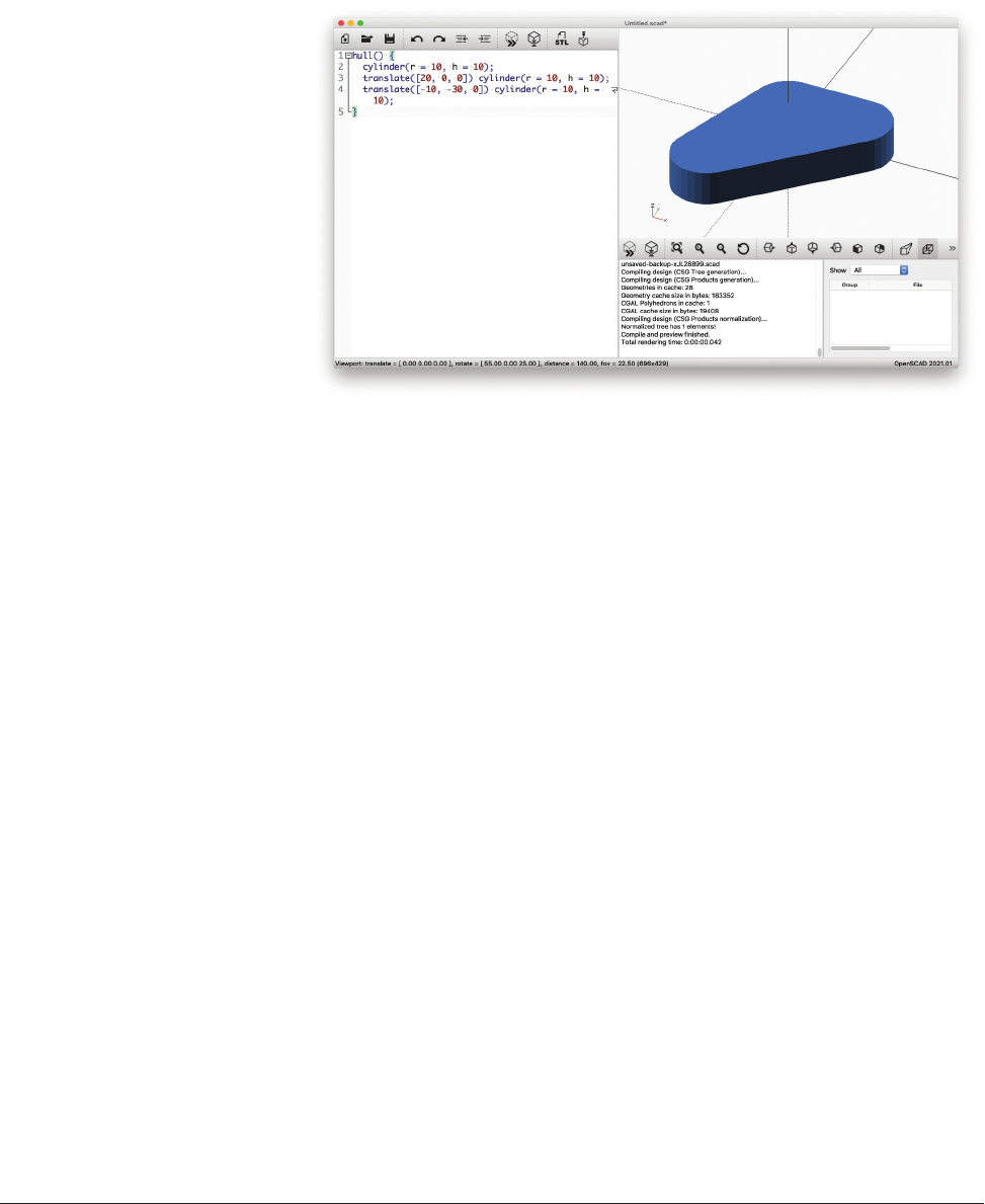
CONVEX HULL
The hull() module combines multiple shapes into a continuous one, connecting across any gaps
among them. It uses a mathematical construct called a convex hull to do this. All this means, really, is
that it connects the shapes in ways that never sag inward into the shape. For example, you can create
a set of points using cylinders, then fill in the space enclosed by them. Figure 3-13 shows the resulting
FIGURE 313: Triangular shape using hull()
48 Chapter 3: Simulating Geometry Make: Geometry 49
Geometry_Chapter10_v15.indd 49Geometry_Chapter10_v15.indd 49 6/23/2021 9:08:44 AM6/23/2021 9:08:44 AM
..................Content has been hidden....................
You can't read the all page of ebook, please click here login for view all page.