

FIGURE 1012: A flashlight making an
ellipse on a wall
FIGURE 1013: A flashlight making a
parabola on a wall
FIGURE 1014: A flashlight making a
hyperbola on a wall
PRELUDE: FLASHLIGHT EXPERIMENT
If we take a flashlight and point it at a wall, we are creating a cone of light.
Let’s try tilting that cone relative to the wall to see if we can create the
conic sections. If you have a flashlight smaller than a toilet paper roll and
can shine the flashlight through the tube at the wall, the following experi-
ment will have better results than just a flashlight with stray light diffusing
everywhere. In our case, we took a cell phone (which has a good lens over
its light) and put it in flashlight mode. Then we cut about a 2-inch long piece
of a toilet paper tube to make the light come out nice and parallel, and held
that against the phone. You can see the toilet paper tube in the images. You
can use a regular flashlight, but they tend to have parabolic reflectors (more
on that later) so you get more complicated effects. We will refer to a “flash-
light” in what follows as meaning a light through a toilet paper tube.
Take the flashlight and shine it straight at the wall. You will get a circular
spot of light on the wall (Figure 10-11). But if you start to tilt the flashlight a
bit, the circle will stretch out along one axis and become an ellipse (Figure
10-12). If you tilt it at an even greater angle to the wall, eventually one end
of the ellipse will open up, and you have a parabola (Figure 10-13). Finally, if
you tilt the light even further, you will get one branch of a hyperbola (Figure
10-14). If you do an internet search on “conic sections flashlight” you will find
video examples, too.
Make: Geometry 209
208 Chapter 10: Slicing and Sections
Geometry_Chapter10_v15.indd 208Geometry_Chapter10_v15.indd 208 6/23/2021 9:10:50 AM6/23/2021 9:10:50 AM

FIGURE 1015: The set of all the sections (model printed twice)
MODIFYING THE MODELS
Let’s fine-tune our understanding of when a cut
will give us one or the other conic sections. The
model conic_sections_set.scad prints a cone
with cuts that create the various cross-sec-
tions. You might need a bit of double-sticky tape
or museum putty to hold this model together,
depending on the slipperiness of the filament
you are using. For the photos in this chapter, we
printed two sets using different color filaments
and re-assembled the cones while alternating
the pieces to make the cuts more visible (Figure
10-15). As with the prism slice models, the two
sides of the cut are beveled on one side and have
a lip on the other. This makes it clearer where the
cut is, and helps them hold together better when
you assemble the set.
The model conic_sections_set.scad has the
radius of the cone and its height equal to each
other, and we do not recommend changing any
parameters since the relative arrangements of all
the cuts are carefully calibrated not to cross each
other. This model is best scaled in your slicer if it
needs to be bigger or smaller. Be sure that you
scale all axes by the same amount.
If, on the other hand, you want to explore just one
cut through a cone, the model conic_section.scad
has the following parameters you can change:
• r, the radius of the cone, in mm
• h, the height of the cone, in mm
• slicetilt, the angle (in degrees) about
which the cutting plane is rotated
• Two parameters for the position of the axis
about which the cutting plane is rotated:
sliceheight in the z-direction (mm),
slicehoset in the plane of the base of the
cone (mm).
FIGURE 1016: Definitions of sliceheight and slicehoffset
FIGURE 1017: Both sides of the circular cross-section cut.
Make: Geometry 209
Geometry_Chapter10_v15.indd 209Geometry_Chapter10_v15.indd 209 6/23/2021 9:10:52 AM6/23/2021 9:10:52 AM
If sliceheight and slicehoset are both set to zero, the axis of rotation
of the plane is also the diameter of the base of the cone. Since this can be a
little tough to visualize, we suggest going into OpenSCAD and playing with
slicetilt, sliceheight, and slicehoset to see how changing them
affects the placement of the cutting plane (Figure 10-16).
If you don’t have a 3D printer, you could consider creating a cone out of modeling
clay and cutting it at an appropriate angle. You’ll need a protractor to measure
the slant height and the angle you are cutting the cone, and a way to cut it that
won’t distort it.
CIRCLE CROSS-SECTION
Now, let’s deconstruct the model. If we cut through a cone with a plane par-
allel to its base, the cut we make is a circle. How big a circle it is depends on
how far up from the bottom of the cone we make the cut. But any cut paral-
lel to the base will be a circle (Figure 10-17).
Right at the vertex of the cone, the cut would be a point, but that is a special
case. We have a short section later in the chapter about the more general
issues that arise when any cutting plane passes through the cone vertex.
ELLIPSE CROSS-SECTION
If, however, we tilt the cut so that we are cutting at an angle to the horizontal
that is more than zero, but less than the slant angle, we get an ellipse — a circle
stretched out in one dimension (Figure 10-18). Ellipses come up all the time in
astronomy; the orbits of the planets around the sun and the moon around the
earth are ellipses. We will see how to derive an equation for an ellipse, and an
FIGURE 1018: Both sides of the ellipse cut FIGURE 1019: Parabola slice when cone height and radius
are equal
Make: Geometry 211
210 Chapter 10: Slicing and Sections
Geometry_Chapter10_v15.indd 210Geometry_Chapter10_v15.indd 210 6/23/2021 9:10:53 AM6/23/2021 9:10:53 AM

alternate definition of it, as part of our applications of
conic sections in Chapter 11.
The more we tilt the plane, the longer and skinnier
the ellipse gets. Like the circular cross-sections,
the ellipse will be larger if the cutting plane doesn’t
pass very close to the vertex. It’s pretty obvious why
we get an ellipse if the cutting plane is at an angle
to the horizontal greater than zero, since cutting at
a slant elongates one axis. It’s less obvious why the
slant angle is the upper bound. Let’s talk about the
parabola to see where that boundary comes from.
PARABOLA CROSS-SECTION
What happens if we cut through the cone parallel to its side (that is, when the cutting plane is at the
slant angle)? The resulting cross-section is a curve called a parabola (Figure 10-19). Parabolas make
their appearance in many physical situations, notably in parabolic dish antennas or mirrors that con-
centrate light in one spot called a focus. In Chapter 11 we’ll talk about why those systems work. For
now, let’s just see what they look like and how they arise from cutting a cone.
As we saw earlier in the chapter, the slant angle is:
Slant angle = tan
-1
(height/radius)
In this case, since the radius of the cone and its height are the same,
Slant angle = tan
-1
(1) = 45°. We can see the parabola in Figure 10-19.
On the other hand, if the height was 3 times the radius (Figure 10-20), we would get:
Slant angle = tan
-1
(3) = 71.6° (relative to the base of the cone).
We used the model conic_section.scad with the following values to create two cones, one with the
height equal to the base radius and one with the height three times the radius. Other parameters were
the same, as shown. We then tilted the plane appropriately to get a parabola, as we just calculated.
FIGURE 1020: Parabola slice when cone height is 3 times the
radius
Make: Geometry 211
Geometry_Chapter10_v15.indd 211Geometry_Chapter10_v15.indd 211 6/23/2021 9:10:53 AM6/23/2021 9:10:53 AM

Height = radius Height = 3 * radius
h = 50; h = 50;
r = h; r = h/3;
sliceheight = 0; sliceheight = 0;
slicehoset =0; slicehoset =0;
slicetilt = 45; slicetilt = 71.6;
Now let’s look at what happens if we pivot the plane about a different axis of rotation when making the
cut. We printed the cone with h = r and a 45° cut and got a parabola as expected. However, when we
created the cone showing all the cuts at once, we needed to do a bit of adjusting so that the cuts would
not cross each other. It turned out that the offsets for the parabola needed to be:
sliceheight = h * 3 / 4;
slicehoset = r * 1 / 4;
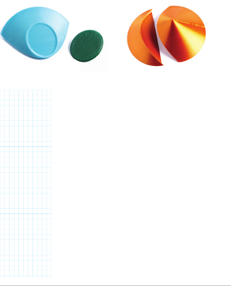
The silver cone shown was printed with these parameters (the same as in the cone showing all the
cuts). The bronze one was printed with both sliceheight and sliceoset equal to zero. You can see
that the slices are parallel to each other, but result in a differently scaled parabola (Figures 10-21 and
10-22).
Unlike an ellipse or a circle, the parabola is not a closed curve. The straight part of the cross-section along
the bottom of the cone is not considered part of the parabola. Planes cutting at the slant angle (and more
steeply) create curves that are not closed (parabola and hyperbola.) You can see why if you look at the parab-
ola’s cross-section: any cut steeper than that would always be cut off at the bottom of the cone. If the cone
was infinite, the sides of the cut would go on forever.
FIGURE 1021: Parallel slices, showing half of each model FIGURE 1022: Parallel slices, with the model assembled
Make: Geometry 213
212 Chapter 10: Slicing and Sections
Geometry_Chapter10_v15.indd 212Geometry_Chapter10_v15.indd 212 6/23/2021 9:10:54 AM6/23/2021 9:10:54 AM
..................Content has been hidden....................
You can't read the all page of ebook, please click here login for view all page.