
// Module that creates the arches
module arch(size, gothic = true) {
if(size[2]) {
linear_extrude(size[2]) arch([size[0], size[1], 0], gothic);
} else intersection() {
union() {
if(gothic) intersection_for(i = [-1, 1])
translate([i * size[0] / 2 , 0, 0]) circle(size[0]);
else circle(size[0] / 2);
if(height > 0) translate([-size[0] / 2, -size[1], 0])
square([size[0], size[1]]);
}
translate([-size[0] / 2, -size[1], 0]) square([size[0], size[0] + size[1]]);
}
}
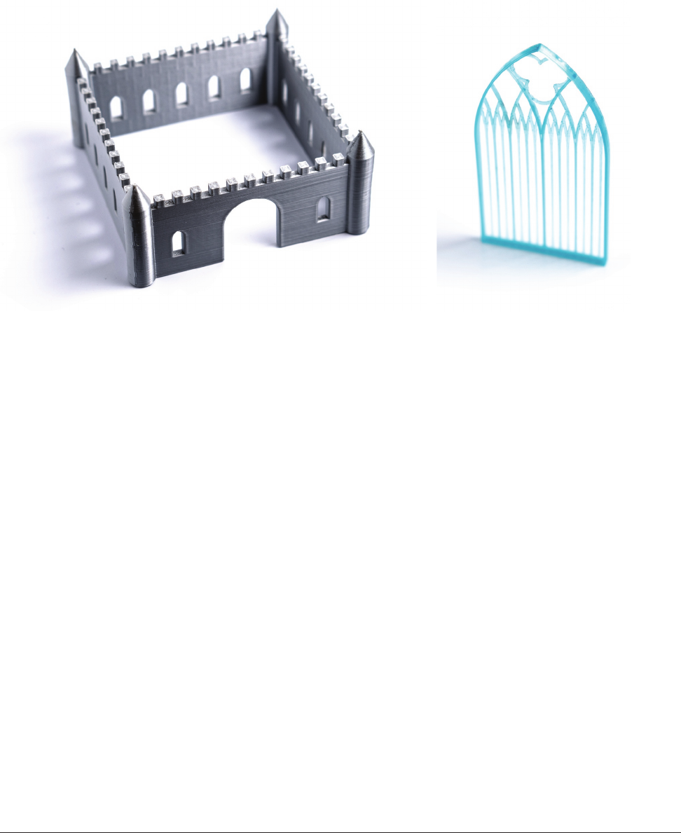
GOTHIC TRACERY
Glass for windows was very expensive and not very strong until just a few hundred years ago. Before
that, large windows were broken into panes by structures called tracery. Then, the open spaces would
be filled in with stained glass. The model tracery.scad allows you to create designs in the spirit of
medieval cathedral windows. Its outer boundary is a Gothic arch, and the shape is repeated to segment
the interior with other, smaller arches (Figure 13-10). In medieval times, the long skinny openings would
have probably needed some cross-bracing, but we will take a little artistic license here.
FIGURE 139: The castle with windows and a door FIGURE 1310: Tracery
Make: Geometry 265
264 Chapter 13: The Geometry Museum
Geometry_Chapter10_v15.indd 264Geometry_Chapter10_v15.indd 264 6/23/2021 9:11:37 AM6/23/2021 9:11:37 AM

MAKING THE MODEL
Here are the parameters you can set in the tracery.scad model.
• size = 60;
• Overall height of the piece, mm
• wall = 1;
• The thickness of the walls, mm
• depth = 5;
• Depth of the tracery walls, mm
• backing = .5;
• The thickness of a backing plate, mm.
If you set backing = 0 the tracery will be open, as in Figure 13-10. If you
want to print the tracery in a transparent material or perhaps paint it, you
would set backing to a nonzero thickness. The rest of the model is a bit
like a Swiss watch; it will be tricky to change too much of it without distort-
ing it. Figure 13- 10 showed it without backing; Figure 13-11 shows it with
it (and the one without backing behind it, so you can compare and see how
translucent you can make a thin backing).
THE TREFOIL
The three-lobed feature in the upper part of the arch in Figures 13-10
and 13-11 is called a trefoil. It appears often in medieval churches,
although more commonly with the two circles on the bottom rather
than on the top, as we have fit it in here.
To generate a trefoil yourself (Figure 13-12):
• Sketch a circle (blue).
• Draw three circles of the same radius as the original one,
120 degrees apart, with their centers on the first circle (red
circles).
• If you remove the interior intersections you will get a trefoil
(marked in black in Figure 13-12).
PRINTING CAVEATS
Printing without the backing (backing = 0) can be a challenging print,
depending on your printer and slicer settings. If you like to make your
first layer width a lot larger than subsequent layers (as we recommend
in general), you may have an incomplete first layer and problems after-
ward. Simulate the first layer in your slicer, and if you see just a few
spots instead of a full tracery back off on your first layer width. We used
150% of our regular line width (as opposed to our usual 200%).
FIGURE 1311: Tracery with backing
FIGURE 1312: Circles comprising a
trefoil
Make: Geometry 265
Geometry_Chapter10_v15.indd 265Geometry_Chapter10_v15.indd 265 6/23/2021 9:11:38 AM6/23/2021 9:11:38 AM

Alternatively, use 0.5mm for backing and your usual line first line width, and your print will look like
Figure 13-11 versus Figure 13-10. In either case, the print is pretty delicate. Pry it off the platform gin-
gerly and don’t tug on those delicate, thin parts.
TRUSSES
In Chapter 5, we looked at how a triangle is stronger than a square. We also saw how adding a cross-
bar to a square makes the square a lot harder to squish. Thus, it may not be surprising that we see
triangles everywhere in bridges, buildings, and other structures. A structure made of triangles is often
called a truss. In this chapter, we are going to try a 3D version of the 2D exercise we did in Chapter 5.
The key thing about a truss is that the joints are free to rotate, but the elements (the straws) are stiff. It
turns out that this means that every element is only pulled on (tension) or experiences forces pushing it
in at both ends (compression). The elements are not being bent, though. A good example is the Mathe-
matical Bridge at Queens College of Cambridge University in Cambridge, England (Figure 13-13).
This bridge was designed in 1748 by William Etheridge and built in 1749 by James Essex the Younger.
According to the college’s website
(https://www.queens.cam.ac.uk/visiting-the-college/history/college-facts/mathematical-bridge),
the design uses many spans of lumber that are much shorter than the total span. This truss design
FIGURE 1313: The Mathematical Bridge, Cambridge, England (Photo by Stephen Unwin)
Make: Geometry 267
266 Chapter 13: The Geometry Museum
Geometry_Chapter10_v15.indd 266Geometry_Chapter10_v15.indd 266 6/23/2021 9:11:38 AM6/23/2021 9:11:38 AM
(called a voussoir arch) is constructed so that gravity causes all the elements
of it to be in pure compression. Supposedly any element could be removed
without affecting the rest of the bridge, although the college notes dryly that
this has never been tested.
Trusses are relatively easy to analyze (although beyond what we can get into
here) and you can look up how to calculate the forces on an idealized truss
in engineering textbooks. But let’s try making a 3D truss and see how it
improves upon a structure that is made up of lots of square elements.
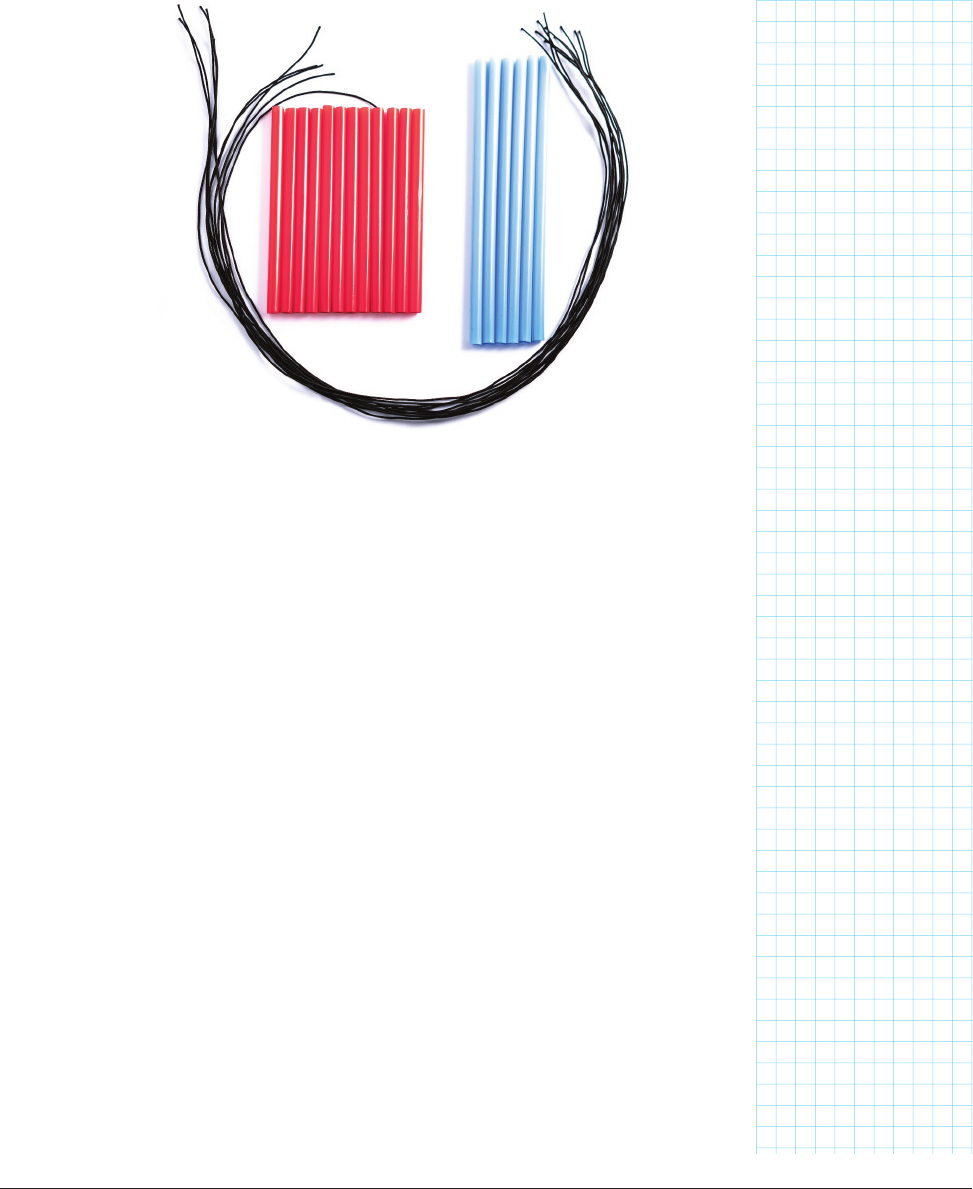
PREPARATION
First, take some stretchy cord (the same as in Chapter 5) and pre-cut your-
self ten strands about 500mm long. These pieces will be going around the
perimeters of a square 100mm on a side and a triangle 140mm on a side,
with enough left over to tie a knot.
Next, gather 18 drinking straws. Plastic straws are the easiest to cut cleanly,
and being pretty precise is important. The straws need to have a big enough
diameter that two threads of your stretchy cord will fit through easily. If
you are using bendy straws, be sure to cut off the bendy part. Cut them as
follows:
• Twelve 100mm (about 4 inches) long pieces
• Six 140mm (about 5.5 inches) long pieces
FIGURE 1314: Assembling the materials for trusses
Make: Geometry 267
Geometry_Chapter10_v15.indd 267Geometry_Chapter10_v15.indd 267 6/23/2021 9:11:39 AM6/23/2021 9:11:39 AM

You must be careful that all the straws in a group are identical, and that the
longer straws (blue in our example) are 1.4 times the length of the shorter
ones (red in the photos that follow). Now you should be ready to start (Figure
13-14).
TETRAHEDRON
First, let’s try making a tetrahedron. A tetrahedron has four identical trian-
gular sides. We will use the six longer (140mm, blue) straws we pre-cut, and
four of the pieces of cord. Take three of these straws and run a piece of cord
through them (Figure 13-15) to make a triangle.
Tie off the triangle (Figure 13-16), but don’t cut off the excess cord just yet.
Now, take another piece of cord. Run it through one new straw, then one side
of the triangle, then up through another piece of straw (Figure 13-17).
Tie off these two new pieces to create a second triangle (Figure 13-18).
Take one last piece of cord. Run it through the final 140mm straw, then
through one of the outer straws of each of the two triangles you just created
(Figure 13-19).
Swing the last piece up and tie off its loose end to make a tetrahedron (Figure
13-20).
At this point, the straws form a tetrahedron, but you still have one triangular
face without a loop of cord. Thread one more piece of cord through these three
straws (the ones with only one piece going through them) to complete the build. If
you don’t add the last cord, the tension on the joints will be uneven, and it may not
work well when we merge it with the cube later on. Tie all ends securely and clip
off the excess. If you cut too close to the knots, they may come undone, so leave
at least a centimeter or two on each one. (Figure 13-21).
Finally, you can move the knots so that they are inside the straws, which will
look nicer (Figure 13-22). Each joint should look like Figure 13-22, with two
cords running through each straw.
Because all of the faces are triangles, this structure will be pretty rigid, even
though the joints are just made of string. How do you think a cube would
behave? Let’s try that next.
Make: Geometry 269
268 Chapter 13: The Geometry Museum
Geometry_Chapter10_v15.indd 268Geometry_Chapter10_v15.indd 268 6/23/2021 9:11:39 AM6/23/2021 9:11:39 AM
..................Content has been hidden....................
You can't read the all page of ebook, please click here login for view all page.