CIRCUIT BENDING
By Cristiana Yambo and Sabastian Boaz

Photography by Bit Shifter
Modify a Casio keyboard (or other electronic audio stuff) and start playing some of the strangest sounds you’ve ever heard.»

SOUNDS OF CIRCUITS
The easiest way to start circuit bending is “playing open circuits.” That’s where you open up an audio device and use your hands or alligator clips to mess with the board inside and see what it sounds like. But it’s almost as easy to permanently “bend” any suitable device by soldering on a few wires and switches. We’ll explain how, and then show you how we transformed a Casio SK-5, a common, 80s-era sampling keyboard, into an unstoppably flexible sound organ and sonic effects generator.
A word of caution: Do not attempt to circuit bend anything that needs to be plugged into a wall, such as a VCR or a television. These devices use high voltages, and playing with the circuitry inside might injure or kill you. Circuit bending is for battery-powered toys and instruments only.

Illustrations by Mark Watkinson
For Your Listening Pleasure
Project co-author Sabastian Boaz has produced several electronic music CDs that feature sounds from his bent instrument collection. His older music relied heavily on circuit bending, and his latest CD, Head Drone, builds on these roots by incorporating crazy electronic sounds generated using a variety of techniques.
![]() You can listen to some of Sabastian’s music, along with other bent instrument recordings, at makezine.com/04/circuitbending
You can listen to some of Sabastian’s music, along with other bent instrument recordings, at makezine.com/04/circuitbending

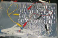
To make bends permanent, solder wires and switches to the connection points. The easiest method is to bridge the points directly. This project brings them out to a patch bay that allows arbitrary connections, for greater flexibility.
ALIEN LIFE FORMS
The father of circuit bending confronts the normals.
It’s hard to know who invented electronic music synthesis, but you could say that Reed Ghazala uninvented it. He coined the term “circuit bending” and has been the technique’s spiritual father and first major practitioner.
Ghazala stumbled on the idea in 1967. “I was 14 going on 15, in junior high and craving my own synth, but penniless,” he recalls. “In my desk drawer was a junked mini amplifier made by RadioShack, battery installed and back off, exposing the circuitry. Closing the drawer after a search for who-knows-what, my room was suddenly filled with weird electronic music: strange ‘flanged’ oscillator sweeps rising in pitch, repeating over and over again.” The amplifier had shorted out against something metal, and that led to a revelation: what if you shorted out circuitry intentionally?
Reed’s first instrument took advantage of this idea, but audiences didn’t immediately take to the avant-garde sounds. “Rowdy Elvis fans” at an early gig physically attacked Ghazala, hoping to “send me and the band to the emergency room,” he says. “But their main target was my instrument. It symbolized a notion of music beyond verbal ballad, telling stories in a language they couldn’t understand.” The audience succeeded in destroying the instrument.
Despite the lack of early audience support, Ghazala was hooked on creating something new and alien, and his audience-obliterated instrument was followed by decades of prolific instrument building. “When I was first body-contacting bent instruments, I realized neither the circuits nor I stopped at our ends anymore,” says Ghazala. “I was extended into the circuit and the circuit was extended into me. We shared the vital electricity that we each depended upon to function, to live. We were no longer two separate entities, like guitar and guitarist. We, literally, were one.” He calls the combination a “Bio-Electronic Audiosapian,” or BEAsape.
Circuit bending, Ghazala explains, means dropping your intentions. “When I hack a radio receiver, I may clip some diodes in it so that I can tune into a wider frequency range. But that’s not circuit bending, because I know where things are going to go. With bending, you cannot presume what you’re going to find — just like sending a probe into deep space.” And outside presumption lies an alien world filled with alien sounds.
Ghazala’s instruments certainly look alien, with flashing lights, eyeballs, laser controls, and hand-inked patterns that resemble psychedelic extraterrestrial animal prints. Ghazala considers his creations more organism than art object, with body modifications that allow them to “sing things they couldn’t sing before.”
“Their main target was my instrument. It symbolized a notion of music beyond verbal ballad, telling stories in a language they couldn’t understand.”
Perhaps Ghazala’s instruments have grown eyeballs and skins because they’re evolving. Nearly 40 years after his first experiments, circuit bending has become a worldwide phenomenon. “As the art of circuit bending claims more territory, spreading through the music underground like alien bacteria,” Ghazala says, “it’s infecting more and more circuitry every day.”
—Peter Kirn
![]() Ghazala’s tutorial on how to build an Incantor is available at makezine.com/04/circuitbending.
Ghazala’s tutorial on how to build an Incantor is available at makezine.com/04/circuitbending.
Peter Kirn is a composer, musician, and media artist; his blog (createdigitalmusic.com) regularly covers circuit bending and other far-out music technologies.
SET UP.

Photograph by David Albertson
MATERIALS
[A] Casio SK-series keyboard We used an SK-5, but they’re all great for bending. Check local thrift stores or eBay.
[B] Stranded wire 22-gauge or thereabouts
[C] Small machine screws and nuts At least 77 of each
[D] Flat, non-conducting, easily drillable box For the patch bay, we used a translucent plastic storage box. The patch bay box should be big enough to hold and permit access to 77 screws without crowding.
[E] Flat, non-conducting box Like above, but smaller; for external key box controller (optional)
[F] Assorted switches, contacts, and other bend components For the control panel. We used 4 toggle switches, 1 potentiometer, 1 photometer, 2 doorknobs (for body contacts), and a pushbutton momentary switch to reset the device.
[G] Flat, non-conducting, easily drillable panel, about 5"x5" For the control panel, which fits over the keyboard’s speaker area.
[H] Hose clamps (2)
[I] Alligator clips At least a few; the more, the merrier.
[J] Ethernet cable For external controllers (optional)
[K] Ethernet jack For external controllers (optional)
[L] Flexible plastic tubing
Momentary switches We used keyboard keys from an old Macintosh. In many older, heavier computer keyboards, each key is its own self-contained momentary switch (not shown).
TOOLS
[M] Soldering equipment
[N] Glue gun and hot glue
[O] Multimeter
[P] Drill and drill bits
[Q] Rotary tool and bits
[R] Electrical tape Multiple voltage transformer (optional, not shown)
MAKE IT.
BEND YOUR CASIO SK KEYBOARD
START |
Time: A Weekend Complexity: Medium |
1. CONNECT THE PATCH WIRES
The chips on Casio SK keyboards contain vast potential for unruly sounds, and wiring up a patch bay unlocks all of it by making every possible pin-to-pin connection available.
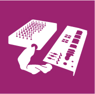
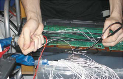
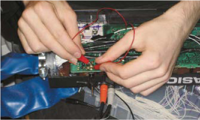
1a. Find the main chips. Open the case, remove the motherboard, and identify the main sound processing chips; these are two large, rectangular chips next to each other in the middle of the board. Each has 14 pins per side, a total of 56 pins. Turn the board over and find the points of these pins on the underside. You will solder one wire to each of these.
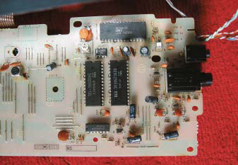
1b. Solder and check wires. For each row of 14 main chip pins, solder 14 lengths of wire, each around 30 inches long, to the contact points underneath. Carefully check each pin for solder bridges. When you finish a row, replace the board and play the keyboard to see if it still works normally. If it makes any weird sounds, you probably bridged two pins together. You can also use your multimeter to test pairs of wires for continuity and resolder wherever you find one.
Photography by Cristiana Yambo
1c. Insulate. Once each row passes its test, cover its pins in electrical tape, and wrap the wires in electrical tape to create a nice cable. After you’ve soldered and checked all four rows, remove the tape covering the pins and test the unit again. When it passes the test, warm up your glue gun and cover each row in hot glue. This holds the wires in place and insulates the connections to prevent unintended short circuits.

2. BUILD AND CONNECT THE PATCH BAY
Some people construct patch bays using RCA jacks, but screws and alligator clips are cheaper, more compact, and they let you connect multiple clips to the same point, which vastly expands the sonic possibilities.
2a. Drill the holes. Measure, mark, and drill 60 holes in the patch bay box, four rows of 15, one for each of the 56 wires, plus four jumper points on the side to facilitate multiple connections. The holes should fit your screws snugly. Leave room for another, smaller set of holes for the control panel which you’ll drill later.

2b. Insert the screws. Bolt screws into the holes, with the heads on the inside and the shafts pointing out.

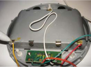
2c. Make the patch cable. Count your control panel components, and then strip and cut enough wires to connect to each of these, plus two more for the tuning circuit; we used 17 total. You’ll connect these wires later, so it helps to include some extra ones and label which ends connect to one another. Gather them together with four taped-together sets of patch wires, to make a super-cable that will run between the keyboard and patch bay. Secure each end with hose clamps, and push it through the plastic tube.
2d. Route the patch cable. Cut a large hole in the side of the patch bay box. Insert the patch cable and secure it by hot-gluing the hose clamp to the box.

2e. Connect the patch wires. Now it’s time to wire the screws. Wrap the end of each patch wire clockwise underneath the head of each screw and tighten the bolt to secure the wire. Connect each group of 14 patch wires to a different row on the patch bay.

2f. Test the board. Using alligator clips, connect switches and pots between different patch points, play the keyboard, and see how it works. Operating the components and changing their configuration should yield different sounds.
3. REMOVE THE TUNING POT
Many old electronic instruments easily lose their tuning and have a small potentiometer that adjusts them back into tune. We’ll bring this component’s connections out to our patch bay, so you can create bends that alter the pitch of the entire keyboard.
3a. Unsolder the pot. The SK’s tuning pot is normally accessed through a hole in the underside of the keyboard, in the center, and you adjust it with a small screwdriver. Find the component on the board and use a solder sucker or desoldering braid to remove all of the solder.

3b. Pull out the tuning pot. You will probably have to use some force. Then mark where it was located, to help you find it later.

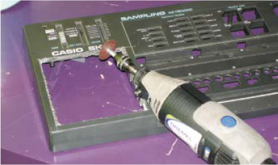
4. BUILD THE CONTROL PANEL
The control panel houses interface components which you can hook into any circuit bends via the patch bay. It also has the reset button, a momentary switch that restarts the instrument after a crash.
4a. Cut out the speaker grill. Using a rotary tool, cut out the speaker grill.
This hole is going to be used to house the interface elements.
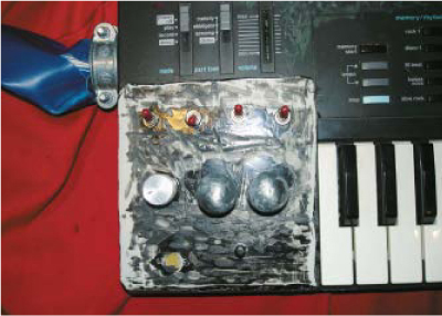
4b. Build the control panel. Attach your components to the panel. For ours, we drilled holes in a piece of hard plastic and then hot-glued in our components: four toggle switches, a pair of doorknobs for body contacts, a potentiometer (separate from the tuning pot), a photometer for light-sensitive distortions, and a momentary switch, which will act as a reset button.
5. CONNECT THE CONTROL PANEL
5a. Finish the patch bay. Drill holes and install screws in the patch bay, as in Step 2. You’ll need the appropriate number of contact points for each component on the control panel, plus two more to lead to the tuning pot’s contacts on the circuit board. Arrange the holes in the same way that your components are arranged on the control panel. This makes it easy to remember which contact point on the bay corresponds to which control.

5b. Wire the control panel. Now you’re going to use the extra wires in the cable. If they aren’t labeled, use a multimeter to identify matching ends. Then connect the control panel components to the new patch bay array, following your logical mapping. Screw the wires to the patch bay points as before, and solder the other ends to the components.
5c. Connect the tuning circuit. Screw two remaining extra wires to the tuning-circuit points on the patch bay and solder the other ends to the tuning pot contacts on the board.

6. CONNECT THE RESET, AND CLOSE IT UP
Bent instruments sometimes crash in a way that disables the power switch. One solution is to wire a momentary switch between the positive power line and the circuit board, but with the SK-5 it’s easier to install a switch that connects the positive and negative power lines, momentarily shorting them out.
6a. Connect the reset button. Solder the reset button’s contacts to the positive and negative terminals that lead from the battery compartment.
6b. Hot-glue the control panel to the case.
6c. Close up the case. Screw it together, switch it on, and then rock out with the ultimate SK!

FINISH X
NOW GO USE IT ![]()
USE IT.
JOIN THE CIRCUITS
MAKING TOYS PERFORMANCE-READY
One of the great features of this project is that the patch bay also allows you to connect other devices to the keyboard’s circuitry. For example, we alligator-clipped the output of an iPod to our SK-5’s tuning-pot contacts. This made the waveform of the music playing on the iPod modulate the pitch of the SK-5’s output, an amazing effect.
Body contacts can be played with various parts of the body at different pressures for different effects. Touching a body contact with your tongue gives very low resistance, which can translate to an extremely high pitch — and electrocute your tongue a little bit.
SK-series keyboards, like the one used in this project, have wall warts and audio jacks. This means they won’t run out of juice, and you can amplify them directly and record them by plugging them in. But many bend-worthy audio toys lack these two essentials. Here’s how to remedy the situation.
Adding an Audio Out
With a toy that has only a speaker, you can make an audio out by connecting the two wires that feed the speaker to a standard mono audio jack or a cut audio cable. If the wires are colored, you can follow the convention of connecting red to the tip and black to the ring. But the order shouldn’t matter; either way will work fine.
With some toys, output to the speaker might be high enough to cause distortion. To bring it down to regular analog audio signal levels, add a resistor inline to the wire that connects to the tip. Experiment with different values to find one that works.

Adding a Power Source
Add the battery voltages and find an adapter with the same total voltage — you may already have one from some old appliance. Confirm its voltage with a multimeter (labels can be incorrect) and determine its polarity, which is usually but not always tip positive, ring negative. If it checks out, solder wires from the negative and positive ends of the toy’s battery tray to the corresponding contacts of the DC in.
Toys sometimes list an amperage. You can usually ignore this, but if the circuitry is especially sensitive, test the power adapter’s amperage along with the voltage. Again, trust the multimeter, not the label.
WELCOME TO THE WARPED WORLD OF CIRCUIT BENDING
If you’ve grown weary of computer software for look-alike, sound-alike musical instruments, you might have something to learn from Adrian Dimond. His latest project is making modified experimental sound creation devices out of Furby toys.
Dimond, aka Xdugef (xdugef.com), unwinds from his day job as a motion graphics artist by producing raunchy electrical noise. His tools of choice range from modified CD players and ancient reel-to-reel tapes to educational phonics toys and a flanger effects box. That might sound archaic, but Dimond is hardly alone. Fueled by online instructions for device modification, circuit bending has become a phenomenon. Nine Inch Nails uses bent instruments now, and you can hear experimental artist Oval’s skipping CD players in a Calvin Klein fragrance ad. Bending’s exposure may have gone mainstream, but the sound is far from conventional: bent creations are adored for their noisy, unpredictable nature.
Popular instruments for beginning benders include the plentiful Casio CZ-1 keyboard and the venerable Texas Instruments “Speak &” talking toy series (Speak & Spell, Speak & Read, Speak & Math). Whereas bending once involved countless hours of adjusting circuits with what-if pokes and prods, online treasure maps and tutorials make it easy for newcomers to the field. And once you’ve cut your teeth with one of the more well-documented devices, plenty of unexplored frontiers remain, particularly the more complex digital devices.
The gamut of bending projects is virtually limitless. Some works are art objects as much as instruments, sculptural creations with elaborate cases and what Dimond describes as “Duchampian collage.” Others are more utilitarian, salvaging plastic cases or simply painting absurd illustrations on the bent object. Many are tongue-in-cheek, merciless modifications of toys.
Dr. Age of the U.K. band Cementimental has warped Nintendo games into video art, and built bizarre instruments out of a Ghostbuster voice modifier toy, a Pikachu keychain, and a plastic toilet, which he converted into an optical Theremin. Techdweeb (techdweeb.com) has taken on dancing daisy toys and the infamous talking fish Billy Bass. Carrion Sound (carrionsound.com) has done unspeakable things to Howdy the Talking Pony.


It’s a little premature to talk about a circuit bending "scene" yet, particularly since it’s hard to know where to draw the lines between "true" circuit bending, device modification, instrumental abuse, and more general noise art. But amidst the countless experimental performances around the world, there’s clearly a growing interest in festivals and workshops focused on bending. New York City is a major epicenter, with numerous concerts and classes and the Bent Festival, held in 2004 and 2005 at The Tank (thetanknyc.com). Bending festivals are also in the works for California and Virginia, and Los Angeles’ Il Corral (halfnormal.com/ilcorral) has established itself as a West Coast hub for noise and sound art.
In the meantime, benders share hundreds of websites featuring music, schematics, photo galleries of various creations, and (sometimes heated) message boards and mailing lists.
—Peter Kirn
RESOURCES
Circuit-Bending: Build Your Own Alien Instruments, by Reed Ghazala
Reed Ghazala’s site: anti-theory.com/bentsound
Other bending and noise art sites: cementimental.com/links.html harshnoise.com
Discussion groups: groups.yahoo.com/group/bendersgroups.yahoo.com/group/bendersanonymouslaunch.groups.yahoo.com/group/Roil_Noisep206.ezboard.com/biheartnoise
Composer, musician, and media artist Peter Kirn profiled Reed Ghazala on page 92.