D.I.Y.
MUSIC

Photography by Warren Young
Your MP3 player’s music will sound minty fresh when played through this li’l headphone amp.
MINT-TIN AMP
Pocket amplifier punches up headphones. By Warren Young
Headphone amps make portable listening good and loud. Commercial audiophile models can cost $200+, or you can build a great-sounding amp inside a mint tin for around $30, following Chu Moy’s popular design. Powered by a 9-volt battery, this amp drives high-impedance headphones to thunderous volumes from even weak sources.
To make one, you need an op-amp chip (like the TI/Burr-Brown OPA132), capacitors, resistors, an LED, and a small prototyping board, plus optional knobs, switches, and other bits, all easily obtained. And, of course, you also need a pocket-sized box, like a Penguin or Altoids tin. See the website listed at the end for a full parts list, along with layout diagrams and more detailed instructions.
Prepare the Protoboard
Start with a small prototyping board such as RadioShack’s model #276-150 — anything that has at least 12 rows of holes and fits into your case. Larger protoboards can be cut down to size with an X-Acto knife. Then solder nine jumper wires as shown in Fig. 1 on page 133.
The jumpers lower down along the edges are what I call “M-jumpers.” They tie three two-hole pads together to form a single pad with three free holes. You can make these by taking a one-inch piece of stiff wire, folding it in half, pinching the kink tight with pliers, and then bowing the two ends over. You may also need pliers to stuff the thick middle bit into the hole. Some people make the same connection by threading “S-jumpers” through to the other side, but this makes the jump less visible.
Build the Power Supply
Solder in the capacitors, and use them to orient everything else. Make sure you put the legs in the right holes — the jumpers you placed previously dictate the path of current flow, so there’s no room for “creativity” now. All the electrolytic capacitors are polarized, so you must orient them properly. If one leg is shorter than the other, the short one is negative, and there should also be a stripe or other mark on the negative side.
Now solder the LED and the current-limiting resistor. As with the capacitors, the short/negative leg of the LED should lead to the negative side of the power supply, with resistors in series in between. If you’re mounting the LED on the lid of the mint tin, solder the resistor close to the board and cover the joint with heat-shrink tubing. That way, its legs won’t flex and snap from repeated openings of the case (see Fig. 1).
On the underside of the board, solder two 2-inch hookup wires to each side of the third row, in the holes marked V+ and V- (for voltage) in Fig. 1. Leave the other ends dangling loose, but don’t let them touch while power is applied.
Now figure out a temporary way to add power to the board. For example, you can solder a 9V battery clip’s leads into the holes marked “Batt +” and “Batt -.” This only needs to work until you start working on the case.
To test the power, set your meter to DC volts, apply power to the board, and measure from the signal ground (“Ground” in the diagram) to the hookup wires going to the V+ and V- holes. With a fresh 9V battery, you should see about +4.5V DC and -4.5V DC at each capacitor, respectively, and their magnitudes should be nearly identical. If you’re off by more than a tenth of a volt, check the wiring and look for solder bridges, wayward drips of solder shorting out to neighboring nodes. Fix any problems and unplug the power supply before continuing.
Add the Amplifier
Solder the IC socket to the board with the notch away from the power supply. Leave one or two rows of holes between it and the power supply caps; use two rows if your caps are exceptionally large. Insert the op-amp into the socket. While placing the other components, refer to the pinout diagram on the op-amp’s datasheet.
Next, add all the resistors (see Fig. 2). Notice in the photo on page 135 that I used jumpers in place of R5. I almost never install these resistors; they’re there to quiet the low-level hiss that you hear with some low-impedance headphones. If you hear a low hiss at normal volume with the audio source disconnected, you can try adding two 47 to 100Ω resistors in the R5 positions. But don’t do this otherwise because it will raise the amp’s output impedance, inhibiting control over the headphones.
For the remaining resistors, I add them in matched pairs: for each resistor in the left channel, I use my ohmmeter to find another that measures as close to identical as possible for the right channel. I haven’t scientifically studied whether this really helps, but it’s easy and quick, so why not? It’s one less thing to blame if the final product’s sound has flaws.
Now add the input capacitors (C2). These aren’t polar like the electrolytic power supply caps, so you can orient them any way you like. Axial capacitors are easiest to fit into tight spaces, but most caps can be made to work with a bit of creative lead bending.
Next, take the hookup wires coming from the V+ and V- points in the power supply area and run them to pins 4 and 8 of the op-amp, the chip’s V+ and V- points. I recommend you do this on the bottom side of the board, since you’ll be adding more wires to the top later. The more wires you can put on the bottom, the cleaner the top side of the finished amp will be, facilitating any repairs and tweaks later.
Finally, add test points at R.out and L.out, and also at R.in and L.in if an alligator clip can’t attach to the input capacitor leads directly (see Fig. 2). I use half-inch pieces of stiff wire, usually clippings from resistor and capacitor legs, bent in an upside-down “U.” These are temporary, used only for the signal test, the next step.
Illustrations by Warren Young
Test the Amp
Now you’re ready to see if you have an amplifier yet or not! Apply power to the board, and let it sit a bit. Then, carefully touch the op-amp and all the resistors’ bodies to make sure nothing is overheating. You shouldn’t feel any heat at all; if you do, unplug the power and find out what’s going wrong.
MINI-CMOY POCKET AMP WIRING DIAGRAM


Fig. 3 Add panel components, enclose, and enjoy!
Green wire = Gound Red wire = Right channel White wire = Left channel
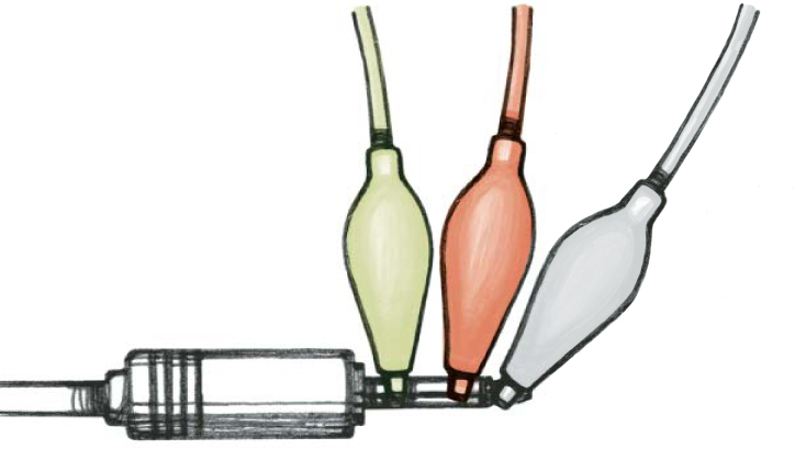
Testing the circuitry: Plug a stereo mini-to-mini cable into any audio device, and use alligator clips to connect the other end to your circuit board. The plug’s tip (left channel) goes to the L.in test point (see Fig. 2, page 133), the plug’s ring (right channel) goes to R.in, and the sleeve goes to ground. Then take some headphones and alligator-clip three more connections to L.out, R.out, and Ground. Play some music, and see if it all works.
I use a portable CD player for testing since they have volume controls, useful when you’re testing a circuit without a volume control. Turn the player’s volume all the way down and start it playing.
Hook the source into the circuit. There is no one right way to do this, but I use six alligator jumpers and a mini-to-mini audio jack cable. I plug the cable into the player’s headphone out and connect three jumpers to the other end. For ⅛" and ¼" stereo mini plugs, the tip carries the left channel, the “ring” further down is the right, and the long remainder, the “sleeve,” is the ground. I clip one jumper to each of these, and then clip the other ends to the corresponding test points and across the ground jumper on the board, as shown above.
Then I use the other three alligator jumpers to tie my amp’s output points to a pair of cheap headphones. Don’t use your $200 cans for first tests — if something’s hooked up wrong, you can blow your cans’ drivers out.
With the headphones sitting on the table, slowly turn up the volume on the player until you can hear some sound out of the headphones. Put them on now and adjust the volume. If you get good sound, you’re done! You might listen for a while longer and try to stress the amp a bit, but basically, you hooked the amp up right the first try. Once you’re satisfied that the amp circuit is behaving properly, try your good headphones with the amp. Sometimes efficient, cheapie ‘phones will work fine, but the higher load of big, audiophile headphones causes problems.
Amps that don’t work right exhibit different symptoms. With some, you’ll hear nothing at all, or the sound will be faint or scratchy, even with the player volume turned up. Others sound fine at very low volumes, but distort when louder. And in some cases, the amp plays for a short while, but then stops. This last case comes from the op-amp shutting down; op-amps often have power-protection circuitry, which is triggered by various wiring faults.
Troubleshooting is difficult, and I can’t cover it deeply here. But the main things to check are that all the connections to ground are solid, and that you don’t have signals or power going to ground when they shouldn’t. Check all connections with your meter; sometimes a connection will look right but have high resistance, in which case it needs to be re-soldered.

Alligator jumpers all hooked up for testing, from music source (I use a CD player) and headphones. Be sure to use a cheap pair of headphones, because an improperly wired circuit can destroy the headphone’s drivers.
If your wiring fully checks out, try adding a second battery temporarily, in series with the first. If that cleans the sound up, your circuit or opamp are marginal. You can either keep on using extra voltage and build for two batteries or try to improve your implementation. See the article, “Basic Troubleshooting for Headphone Amplifiers,” at tangentsoft.net/audio/trouble.html for more advice.
Set Up the Enclosure
With the amplifier board built and tested, you can decide where on the case you want to place the panel components — the volume control, power switch, LED, and I/O jacks. To minimize the tangle of hookup wire, the exterior ports for these components should be positioned close to where they hook up on the board. Beyond that, it’s your aesthetic judgment. Once you have your layout, drill the necessary holes and set it all up with the board in the case and the panel components fastened into their holes, but not connected to the board. This ensures that everything’s going to fit before you start soldering again.
Add the Panel Components
When wiring the panel components into the circuit, add them one at a time, and retest the circuit after each. If you connect all the components at once and then have a problem, troubleshooting becomes very difficult. Also, be sure to test each component on its own, out in the air, and then again once it’s fastened in place. This identifies weak wires, bad chassis grounding, and other issues. I’ve built several amps that worked fine when the panel components were still flopping around on their hookup wires, but failed once the amp was battened down within its case. Fig. 3 on page 133 shows where all the panel components (the switch, LED, in and out jacks, and volume control potentiometer) hook up to the PC board.
First, I hook up the LED and the power switch to the power supply. Once these are working, I add the input and output jacks, remembering the standard stereo plug tip/ring/sleeve ordering described above. I connect and test each one at a time, and use extra-long wires for the inputs. That way, it’s easy to splice in the potentiometer, which is the next and final step.

The completed amp. Unless you want to build it in a day, including the time to get the parts, there’s little reason to get RadioShack parts; the big mail-order houses have everything RadioShack has and more, with cheaper prices and better quality. I highly suggest you mail order everything you can, if you can stand waiting a week for the parts to arrive.
The potentiometer has six pins, three in a row for each channel. The middle pin, the “wiper,” connects to the circuit board’s input capacitor, at L.in or R.in on the diagram. The pins on either side of the wiper connect to the input jack and to ground. If you want volume to increase as you turn the knob clockwise, the ground usually needs to connect to the pin that’s on the left, as you face the knob with the pins pointing downward. But it’s best to determine the pin arrangement by checking the component’s datasheet or testing with an ohmmeter; lowering the resistance between the side pin and the wiper means turning the volume up. If you reverse these connections, the amp will work fine, but the volume knob will operate in the wrong direction.
That’s it — now you’ve got an amp! You can enhance it with various tweaks described on the website, including tuning the gain, adding a DC power jack, using different caps and resistors, and improving the virtual ground circuit.
For the full project tutorial site, including a parts list, background articles and other references, and more detailed instructions, visit ![]() makezine.com/04/headphoneamp.
makezine.com/04/headphoneamp.
Warren Young is a software developer who used to think the maxim “beware of programmers who carry soldering irons” was funny. He lives in Aztec, NM.

Silly Putty’s been around for 50 years, and in that time it’s become an international toy classic. Now you can purchase a 5-pound block of the original Silly Putty at crayolastore.com/category. asp?NAV=PUTTY. The block comes in a box; no plastic eggs included. There’s also a Bouncing Putty Mailing List at bulkputty.org/mail/, with instructions on how to get 100 pounds of Dow Corning’s Coral Putty at bulkputty.org/ordering/dow.html.

VJs’ rigs are all different; unlike with DJing, there’s no standard “two turntables and a mixer.”
Illustrations by Damien Scogin
VJING 101
Performing live video combines the visual power of filmmaking with the spontaneity of jazz.
By Paul Spinrad
It’s a great time for live visuals. After a century-long march of color organs, visual music, light shows, and club videos, visualists can finally manipulate and mix original material and samples, both abstract and representational, in real time. You don’t have to wait for rendering anymore. Most new laptops with dual-screen support (a VJ must) can now handle live video mixing and effects in resolutions of 320x240 or 640x480, depending on the software — and of course, they’re getting better every year. With a super-fast gamer laptop, you can go even higher.
Meanwhile, the home theater boom has brought a flood of dazzling and relatively inexpensive digital projectors. Today’s lightweight, $800 DLP projectors have far higher brightness and resolution than the bank- and back-breaking Eidophor projectors that defined the dance club look of the 1980s. Between a laptop and a digital projector, you have all the hardware you need to start VJing.
Software
Recent years have seen an explosion of live video software. Some apps, such as Videodelic, Touch, and Zuma, are mainly synthesizers that use gestural input and settings to generate dazzling abstract patterns. Other software focuses on playing and mixing video clips.
The easiest clip-based applications to learn, including Arkaos, Motion Dive, and Livid Union, use the interface metaphor of DJing: you see two preview screens (instead of turntables) on either side of a slide control, or “fader.” You trigger video clips by clicking on their thumbnails, paging through your collection as desired, and you can apply effects and mixing algorithms to both.
VJ-ABLE GEAR
There’s almost no VJ-specific hardware, but you can control live video with many other devices.

Joystick A game controller navigates VJ software fast (and VJing resembles gaming, but with an audience).

Touch Controller The STC-1000’s abstract interface won’t make you think you’re playing music or a game.
Data Glove Center-stage VJs need to move. The P5 Data Glove works in mouse mode with any app, and reaches its full gesture-recognition potential with MIDI and Max/MSP interfaces. Refer to the p5glove Yahoo! group.

Digital Projector Lightweight LCD or DLP beamers throw your visuals onto the wall (or anything else) for all to see.
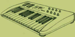
MIDI Keyboard M-Audio’s Oxygen8 keyboard has 25 keys that you can assign to trigger different video clips. Meanwhile, 8 knobs up at the top will tweak effects parameters and other continuous values. A USB port in back of this portable keyboard lets it talk to your laptop directly, without requiring a MIDI-USB adapter.
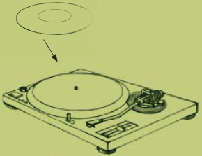
Ms. Pinky Special vinyl LP lets you turn any turntable into a precise controller for playing and scratching video.
Turntable Following their DJ heritage, many VJs use turntables like the Technics 1200 series, outfitted with Ms. Pinky or the EJ MIDI system.
External Hard Drive Hard drives let you store and swap different collections of video clips.

Laptop Live video eats up processing power, so VJs favor RAM-enhancedPowerBooks and gamer PC laptops with fast graphics.
Other apps, such as Flowmotion and Resolume, present a channel-switching metaphor, letting you draw from and layer multiple concurrent video sources. As with the DJ-style apps, you can also apply filters and effects. The most versatile of all VJ applications, such as Isadora, VDMX, and Max/MSP with Jitter, are complete visual programming environments that let you string together clip libraries, live streams, functions, inputs, and outputs to create your own virtual video instruments. Most VJ software runs on Mac OS, but some also run on Linux or Windows.
Accessories
A lot of VJ software takes MIDI input from your laptop’s USB port (translated via a MIDI-USB interface dongle such as the M-Audio Uno or Edirol UM-1X). The VJ applications use this input to synchronize cuts and effects to music coming from the DJ or other source. More importantly, MIDI-in also lets you attach outboard MIDI controllers, which make it easier to perform. Mousing around on a screen can be difficult in a high-energy environment, but with a MIDI keyboard connected to your laptop, you can trigger clips with the piano keys and twiddle settings with physical knobs.
You can also use a variety of other devices to generate non-MIDI inputs as well as MIDI, such as substituting for the mouse and hotkeys on the keyboard. Joysticks, graphics tablets or touch controllers, and data gloves are all tools that can assist your performance — and, to varying degrees, show the audience that you’re not just checking your email while running a DVD of canned visuals.
One special case is scratching video back and forth, DJ style. To perform this move, you can retrofit any turntable with either the Ms. Pinky system, which relies on a special pink vinyl disc and compatible VJ software, or the EJ MIDI Turntable, which uses a barcode-like disc, an optical tonearm cartridge, and a small box that translates your turntablism to MIDI. Alternatively, you can forget the tables altogether, and scratch with a jog shuttle controller such as the ShuttlePRO.
As flexible as laptops are, mixing video and running computationally intensive effects can make a laptop sluggish, or even make it crash. That’s why many dedicated VJs invest in a hardware mixer, such as the Edirol V-4, and put this at the center of their rig. Hardware mixers run their processing algorithms on a chip, which means that they don’t offer the endless array of effects that you can get in software. But they’re faster, immediately responsive, and crash-proof. If you’re hardware-mixer based, you can still use a laptop as one of your mixer’s inputs. VJ applications like Grid2 are designed for this purpose, turning a laptop into a dedicated, fast-triggering clip server.
Content and Culture
The VJ’s palette encompasses all imagery, abstract or representational, recognizable or obscure, iconic or ambiguous. Anything you’ve ever shot, ripped, recorded, generated, or downloaded is fair game, and you can also capture material live from camera or video feeds. Unlike with DJing, you can mix freely, without worrying about key or tempo. The dissonances that a VJ creates are cognitive, not musical, and juxtapositions that give people pause are part of the fun. With a visual vocabulary, ranging from old icons to today’s news, you can construct puns, arguments, and even narratives.
VJing is for the moment, for the people you’re with, growing out of a unique time and place. What you throw onscreen is an expression of the now, not a dead document for posterity. If you want to impose an unchanging visual message on remote, passive audiences, you’re probably better off as a filmmaker. But if you prefer interaction, flow, and living experiences, then VJing may be for you.
Resources
VJ Central reference and forums: vjcentral.com Eyecandy Yahoo! group: groups.yahoo.com/group/eyecandy Eyewash (NYC): forwardmotiontheater.org/Events La-Va (Los Angeles): la-va.org Video Salon (SF): dimension7.com/videosalon.html
Paul Spinrad is projects editor for MAKE and the author of The VJ Book.

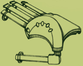
It may look like a camera, but this Logitech QuickCam really wants to be a musical input device.
AIR SCRATCH
Use a webcam to turn motion into music.
By Peter Kirn
Leon Theremin introduced the world to music made from the ether in 1919 with the Thereminvox: wave your hand through the air, and the tube-based instrument produced sound. Now it’s possible to realize new possibilities for controlling sound in the air, all with a cheap webcam and off-the-shelf DIY software.
You’ll need several elements to pull this trick off:
1. A webcam.
2. Motion analysis or “computer vision” software.
3. A means of translating the motion analysis into control (usually MIDI).
4. Something to control, like software synthesizer settings or effects parameters.
The easiest part of the equation is the webcam. I’ve used both an Apple iSight (apple.com/isight) and a Logitech QuickCam Pro for Notebooks (logitech.com/quickcam); I prefer the Logitech camera because it’s cheaper and works well on both Windows and Mac.
There are many forms of video motion analysis, including motion detection and motion tracking. Motion detection responds to any change in the color of specified pixels anywhere in a video source. It can tell if something is moving, but it can’t track the direction of a pixel or object through space. Since you can divide the image into a grid, motion detection works well for camera-controlled drum machines; each grid section triggers to a different percussion sound.
Motion tracking is more sophisticated, tracking a pixel (or object) through space. For continuous control of parameters, like a video theremin, controlling an effect, or scratching in air, you’ll need some form of motion tracking.
Implementing motion tracking from scratch is thorny stuff, but there are many off-the-shelf solutions, a number of them free. Interactive toolkits let you create your own custom software by “patching” visually instead of coding, ideal for handling the motion data flexibly. By transmitting MIDI, they can also be used to control instruments and effects software. On Windows, the free software EyesWeb (eyesweb.org) is perfect; it’s designed specifically for experimenting with computer vision and has plenty of tweakable parameters. Mac and Linux users can combine the interactive toolkit PD (Pure Data, puredata. org) with PiDiP (recursive acronym for Definitely in Pieces, ydegoyon.free.fr/pidip.html). Both PD and PiDiP are open source, though they’re a little less robust when it comes to motion tracking.
The best cross-platform solution is Max/MSP and Jitter from Cycling ’74 (Mac/Windows, cycling74.com); it lacks the ingredients for computer vision but has extensive modular MIDI, audio, video, and number-crunching capabilities. Two cross-platform add-on libraries for Jitter include a full toolkit of computer vision capabilities: the commercial Tap.Tools ($65-$119, electrotap.com) and cv.jit (free, www.iamas.ac.jp/~jovan02/cv). I regularly use both.
Max/MSP/Jitter is an expensive solution, costing hundreds of dollars, but to get you started, I’ve created a simple standalone application developed in Jitter that does the work for you, converting motion tracking to MIDI data. The download, instructions, and details on how it was made are available on the MAKE site ( ![]() makezine.com/04/diy_airscratch).
makezine.com/04/diy_airscratch).
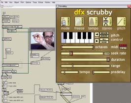
Photography by Peter Kirn
A custom Cycling ’74 Max/MSP and Jitter patch does the work, with the help of the free cv.jit add-on. That yellow dot on top of my hand is tracking movement, which can be routed to an instrument or effect in the form of MIDI data. Here, I’m using the free Windows/Mac VST effect plug-in DFX Scrubby to mangle a looped groove.
You may still want to build your own tool using one of the aforementioned options, but trying out this tool with your favorite instruments and effects will give you a sense of what does and doesn’t work. Some quick fixes to tracking problems include using a brightly colored object for tracking, or shining a small flashlight at the camera (perfect for darkened onstage performances.)
You can construct your own audio functionality using these applications’ modular capabilities, or you can route MIDI data to your audio software of choice. Mac users can route MIDI between applications, easily using the Inter Application Communication (IAC) driver; select IAC in the sending and receiving application, or another virtual in/out, and you’re done. Windows users need to install the MIDI-routing tool MIDI Yoke (midiox.com).
Lastly, you need something to control. I wanted “virtual scratching” ability, so I could wave my hands to shuffle and distort beats. The free audio instrument Musolomo (Mac, plasq. com/downloads) fit the bill perfectly. Destroy FX’s donationware Scrubby and Buffer Override (Windows/Mac, destroyfx.smartelectronix.com) also work well, though for these you’ll need a host that supports sending MIDI to effects, like the free modular host Buzz (Windows, buzzmachines.com).
Put it all together, and you’ve got video control of audio. You’ll need to experiment with lighting, positioning, and your technique, but as with the original theremin, the effort is part of the fun. Especially when the reward is magically pulling music from the ether.
Peter Kirn is a composer/media artist and editor of createdigitalmusic.com.
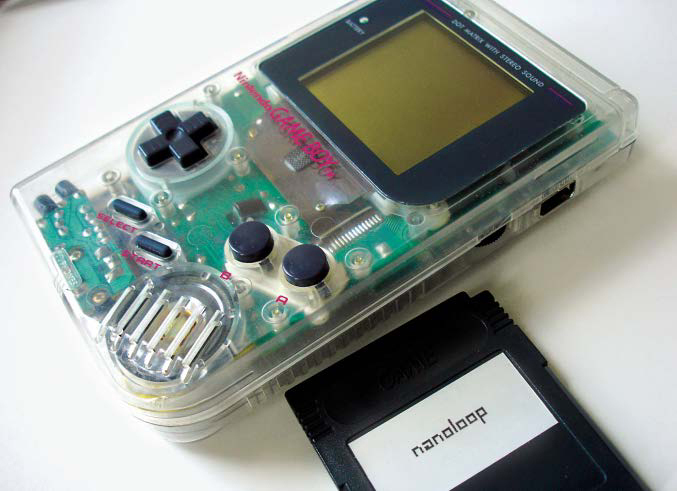
The essential tools of a Game Boy musician: a classic Game Boy and a homebrew cartridge.
MUSIC BOX
Turn your Game Boy into a musical instrument.
By Peter Kirn
To its fans, the low-fi, 8-bit sound of a Game Boy might as well be a Stradivarius violin. So how can you make your original, gray 1989 Game Boy, or even your new DS, into a retro music-making machine?
Cartridges for Music
The easiest way to start out is via the Game Boy Camera, an accessory for the original Game Boy. The camera’s onboard software includes a fairly limited but usable music creation tool. Used cameras usually go on eBay for $10-$20 (about the same price as an old Game Boy, if you’re lucky). The music software is simplistic, but the camera’s photos are appealingly low-res.
For more serious music making, you’ll want a homebrew option; by far, the best are Oliver Wittchow’s Nanoloop (nanoloop.com) and Johan Kotlinski’s LSDJ (littlesounddj.com). These are not Nintendo-licensed, but while Nintendo has made some moves against backup hardware, they’ve generally left homebrew developers alone. Nanoloop 2.0 is available for sale as a Game Boy Advance (GBA) cartridge (€80, US$100). Nanoloop 1.x for the original Game Boy is currently out of production, but an upcoming 1.3 update will make it available again for older systems.
The situation with LSDJ is more complicated: $29 buys you a ROM image, but you’re on your own beyond that. You can load the ROM in an emulator; my favorite is KiGB (Mac/Windows/Linux, kigb.emuunlim.com). An emulator makes screenshots and audio capture easy, but you’ll still want a real Game Boy for portability and authentic sound.
Photography by Peter Kirn
The Game Boy Camera’s DJ game is basic but friendly: the keyboard at bottom chooses pitch, while the rectangles at center are steps in the step sequencer. The tabs at top represent different instruments, the sounds of which can be edited using various parameters in the top third of the screen.
You’ll need linker or “backup” hardware for creating your own flash cartridge, and unfortunately, the classic-style cartridges needed are harder to find than the GBA cartridges. See LSDJ’s website for caveats and up-to-date advice, but the UK-import Game Boy Transferer is probably your best bet (Windows only, www.robwebb.clara.co.uk/shop/copiers/copiers.htm).
Assuming you’ve got a cartridge compatible with your Game Boy, sound quality is your next consideration. Aside from their “oldskool cred,” vintage Game Boys also sound far better than the GBA and Color models, so for Nanoloop 1.x or LSDJ, older is better. With Nanoloop 2.0, you’ll need a GBA model or later; the SP and DS have worked best for me.
Start a Song
Don’t expect to pick up any of these options without a manual or tutorial handy. Here’s some basic advice, but for links to additional tutorials, resources, and some quickie “survival guides,” see ![]() makezine.com/04/diy_gameboy.
makezine.com/04/diy_gameboy.
Game Boy Camera
From the camera’s main menu, select Play. At the beginning of the Space Fever II game that appears, shoot the shape labeled with the letter “D” for the “DJ” game. Select New from the following screen to create a song. Hit Select for the sequencer/editor; hit Select again to toggle between one of three sound types. Since left and right choose beats (or “steps” as they’re called in a step sequencer like this), you’ll need to hold down A+left or right to add a pitch on the keyboard.

LSDJ uses a character-based interface, constructing songs out of sequences called “chains.” The cross in the lower right corner functions as a map of the software’s editing structure. The (P)hrase editor shown here is where the real magic happens. Here, I’ve sequenced a drum pattern using LSDJ’s built-in sampled drum kits.
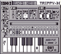
Nanoloop 2.0
Nanoloop is the most graphical of the Game Boy music “power tools.” The grid you see on startup is a step sequencer for an individual channel. First, you’ll want to add some notes, so select the note icon on the bottom (with A+left/right to select the edit parameter). Next, navigate to the step you want to edit (with left/right), and then change the pitch (using B+up/down to edit the step parameter). You can then layer channels (use up/down to select a channel), edit sounds with the instrument editor (hit Start to toggle views), or see an overview of your whole song (hit Select). See Wittchow’s documentation at nanoloop.com/manual_201.html for more information.
LSDJ
LSDJ has the deepest sound and song editing, but it also has the steepest learning curve. It uses hex codes in place of graphics, and is conceptually challenging to beginners because it works much like vintage “tracker” music software (see en.wikipedia.org/wiki/Tracker). The payoff is complex sequencing and nifty features like built-in Roland TR-808 samples; see wiki.littlesounddj.com/ for tutorials and frequently asked questions.

Nanoloop 2.0 uses a minimalist graphical interface that hides some powerful features. Each large gray box is a step in the step sequencer (for constructing loops). By choosing a parameter at the bottom (the note icon represents pitch), you can edit that parameter on each step. A separate instrument editing screen with a similar interface gives you other controls over sound.