
PRIMER
Photography and illustrations by Sparkle Labs
Microcontroller Programming
By Sparkle Labs
Easy-to-program chips tell circuitry to do what you want.
Press a button and a light flashes a pattern. What makes it flash? It seems like there’s a tiny monkey in there flipping the switch. If so, many household items contain these tiny monkeys. They’re what send the infrared (IR) codes out of our remote controls and then decode them in our televisions. They run our washing machines and toasters. These tiny monkeys are microcontrollers, and you can train them to help you with your own projects.
Microcontrollers are small computers, all on one chip. The chip carries a central processing unit (CPU), program memory, data memory, and input/output (I/O) pins that can connect to various devices. The chip works by the CPU following the instructions in the program memory, which tell it what to read and write to data memory, and what to input and output to the pins.
Programming the microcontroller means writing and storing these instructions in the chip’s program memory. The microcontroller speaks assembly language, which consists of binary instructions (ones and zeros). You can program directly in assembly language, but most people prefer to use a higher-level language like C or BASIC because they’re easier to understand. When you do it this way, programming a microcontroller is a four-step process.
This article explains the process. In our example, the chip will simply make an LED flash. This may not seem like much, but the hard part is setting up your programming environment and making all the pieces work together. After you get the light blinking, you can take over the world!
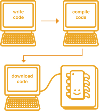
1. Write the code.
2. Compile the code.
3. Download the assembler code onto the chip.
4. Build and test your target circuit.
Low-Level Microcontroller vs. BASIC Stamp Module
First, decide whether you want to use a low-level microcontroller or a BASIC Stamp module. Inexpensive low-level chips (a.k.a. PICs), from Microchip or Atmel, require additional hardware, software, and effort. BASIC Stamp modules, from Parallax and NetMedia, are easier for beginners but pricier.
BASIC Stamps combine their microcontroller with oscillators and other components into one, pluggable package, simplifying circuit design. They also include all development hardware and software.
For our example circuit, we’re using the low-level, two-dollar Microchip PIC 12F675.
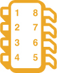
Low-level microcontroller chip
BASIC Stamp module
Microcontroller Programming Hardware and Software
To program a low-level chip, you need three pieces of hardware: a PC, a hardware programmer with compatible cable, and the target circuit that you’ll plug the micro into. You’ll also need some software.
1. PC: The vast majority of software tools for programming microcontrollers run on Windows machines (but see sidebar, page 162). You don’t need a fast machine; any PC with the proper port for your hardware programmer cable (serial, USB, etc.) will do.

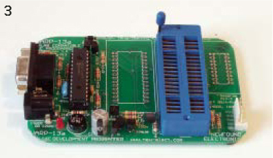
2. Hardware Programmer: This is what you plug your chip into in order to transfer your program from the PC. Traditionally, you then remove the chip and place it in your circuit, but some hardware programmers support in-circuit programming, which lets you burn the chip in place, within the circuit, making it easier to debug and re-run the software.
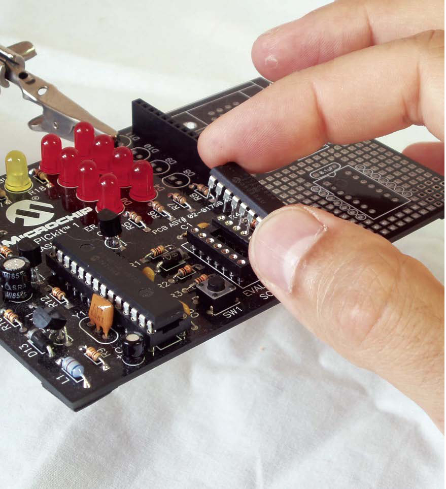
For our example here, we used Microchip’s PICkit 1 Flash Starter Kit, a $35 USB programmer that contains a small demo board and can program some but not all of Microchip’s 8- and 14-pin micros.

3. Target Circuit: If you’re just starting out with microcontroller programming, you can experiment with a demo board, like the one included with the PICkit 1. These are printed circuit boards with a space to plug in your chip and various input and output devices such as buttons, LEDs, and potentiometers. Using one of these boards, you can explore the features of your chip and run different programs without worrying about wiring.
If you have a standalone circuit idea in mind, the next step is to build your own. There are plenty of circuits published online, and you may be able to find one that’s close to what you need. But schematics often contain errors, so you need to be careful. If you’re up to it, you can also design your own circuit from scratch, as discussed below.
Software: In addition to the hardware, you need to put together your software development environment.
This will include the text editor where you write your code, a compiler, the software that drives your hardware programmer (which probably came included with the hardware), and microprocessor simulation and debugging tools.
You can buy most of this software grouped together into an integrated development environment (IDE) from companies like Microchip and Micro-Engineering Labs. We used Proton Lite, a free trial-version IDE that restricts you to 50 lines of BASIC code — which is plenty for our simple blink program.
Designing a Circuit
First, think of what inputs and outputs your circuit will have: switches, sensors, lights, motors, etc. Then you can determine the power requirements. For simplicity, our circuit uses batteries, but a wall-wart with a voltage regulator is more reliable.
Next, determine how your inputs will interface with the microcontroller. Some pins take only digital inputs, a.k.a. logic inputs, where 5V means 1 and 0V means 0. The general rule for these is that power brings the voltage up and ground draws it down. To make a button that changes an input pin from 0 to 1, for example, connect the pin to ground, through a resistor, and also connect it to a button that, when pressed, completes a connection to power.
Some micro pins take analog as well as digital inputs; you can feed these from analog sensors that produce a range of electrical values. For example, a potentiometer’s knob changes its resistance, which changes a voltage fed through it. Connect a pot to a pin that works as an analog-digital (ADC) converter, and the micro will convert the current position of the knob into a number you can program with.
An LED will light up directly from a micro’s output pins, but things like motors require more current. You can supply this by connecting an output pin to the base of a transistor that has higher current running through it. Motors may generate voltage spikes that can damage your chip, but a diode running in reverse across the transistor will protect the circuit.
Once you know which sensors connect to which types of pins, you need to study your microcontroller’s datasheet. As with most micros, pins on the PIC12F675 perform multiple tasks, and you set registers in your software to tell the pins how to behave. In the registers table from the PIC12F675 datasheet on Microchip’s website, we see that the TRISIO register tells a pin to be input or output, and the ANSEL register determines which pins connect to the ADC. These registers have eight bits, one for each pin. So, to connect a simple binary button to a pin, set its corresponding bit in the TRISIO register to 1 (input) and in the ANSEL register to 0 (disconnect). To connect an LED, set the TRISIO to 0 (output). To read a potentiometer value, set the pin’s TRISIO to input (1) and set the ANSEL to connect the ADC (0).
Make an LED Blinky
Here’s how we built and programmed our microcontroller-based LED blinky circuit.
START »
1. SET UP YOUR DEVELOPMENT ENVIRONMENT.
Install the IDE and the PICkit 1 software and hardware. Adjust the IDE settings to make sure it knows where to find the programmer and that it’s set up for our controller, the Microchip PIC 12F675.

Adjusting IDE settings.
2. ASSEMBLE THE CIRCUIT.
Before getting down to building and coding specifics, take a look at the PIC 12F675’s pinouts, from its datasheet on the Microchip website. You can see here how our circuitry’s wiring diagram follows the chip’s pinouts.
Our circuit includes the microcontroller, a power source, a timing crystal, support components for the microcontroller, and the output LED.
PIC 12F675 Pinout
1. VDD
2. GP5/T1CKI/OSC1/CLKIN
3. GP4/AN3/T1G/OSC2/CLKOUT
4. GP3/MCLR/VPP
5. GP2/AN2/T0CKI/INT/COUT
6. GP1/AN1/CIN-/VREF/ICSPCLK
7. GP0/AN0/CIN+/ICSPDAT
8. VSS
Power comes from three AA cells that provide 4.5V, which is close enough to digital logic’s 5V “high” voltage. A 10K-ohm pull-up resistor maintains a high voltage level to the chip’s master clear pin, Pin 4; sending low voltage (logical 0) to this pin would make the PIC reset. A 4KHz oscillator supplies the source blink pulse, which is slowed down by two capacitors. Voltage to the LED comes from the microcontroller’s output Pin 7, connected to ground in series with a 220-ohm resistor.
Follow the wiring diagram at right. We soldered our circuit together using a small piece of perfboard.

A. PIC 12F675
B. Three AA cells
C. 4KHz crystal oscillator
D. 10K Ω resistor
E. 220 Ω resistor
F. 22pF capacitor
G. LED
3. WRITE THE BASIC CODE.
We wrote ours in the text editor window of Proton Lite. Here it is in full, with comments included to explain what’s going on:
Device = 12F675 |
Tell the compiler what kind of chip we are using. |
TRISIO = %00000000 |
Write the byte “%000000000” to the register. |
GPIO = %00000000 |
This line sets all of the I/O pins to be output. |
While 1 = 1 |
1 is always equal to 1, so this creates a loop forever. |
DelayMS 500 |
This makes Pin 7 output light up the LED. |

Proton Lite code window.
4. COMPILE THE CODE.
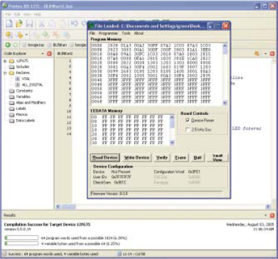
Save your code (which is a plain text file) to your hard drive, and then click Proton Lite’s “Compile and Download” button. This creates a hex version of the file and launches the PICkit 1 software.
Within the PICkit 1 software interface, click “Import HEX” to open your newly created hex file, which was written to the same directory as your original code file. This hex file contains the microcontroller assembly code.
5. BURN THE ASSEMBLER CODE ONTO THE CHIP.
Insert the microcontroller chip into the PICkit hardware programmer and click “Write Device.” It’s that simple; your microcontroller is now programmed!
6. BUILD AND TEST YOUR TARGET CIRCUIT.
One common method is to prototype it on a breadboard. This is what we did for our example.
Plug it into your target circuit, connect up the power, and bask in the blinking glory!

NEXT STEPS
Now you can experiment with other input and output devices. Resistive sensors are fun; these change their resistance in response to things like light, flex, and temperature. You can also use gravity sensors, compasses, accelerometers, and rangefinders.
For outputs, buzzers and small speakers make sounds, and motors give your project legs or wheels. LCD panels show information, and LED matrices make colorful displays.
Mount a rangefinder on a servomotor, and your micro can point it around and read its physical surroundings. Have your micro output serial data to a PC, and you can make a sensor control a game character. We’ve created a lot of fun projects with our little micro monkeys, and we invite you to do the same.

The Platypus Amoeba has touch sensors on its back, and responds to petting with lights and sounds.
FINISH X
Sparkle Labs (sparklelabs.com) is a product development firm in NYC. They build “hi-tech, hi-touch” environments and products, using new technologies to create soft and playful interactions.