This chapter covers the principles of robot motor control that apply to both two wheeled
and four wheeled platforms. The motor controller hardware is explained, as is the code used
to make this functionality accessible to the sketches. The second half of this chapter
(Software Architecture for Robot Mobility) describes software modules that frees the sketch
logic from a dependency on any specific motor hardware. All sketches use the library named
RobotMotor that provides a consistent interface to the hardware
specific motor system. An optional software module named Move provides
high level functions to move the robot that simplifies the code in the more complex sketches
that follow in chapters to come.
This chapter uses the AFMotor shield described in Chapter 2.
The motor control code used in Chapter 6 is explained and two new sketches are introduced:
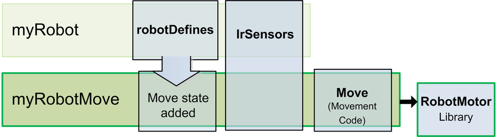
MyRobotCalibrateRotation.ino—A sketch for running the robot through a range of speeds to calibrate the robot.MyRobotMove.ino—This sketch shows how to use higher level movement functions. Constants for defining the current robot movement are added to the robotDefines tab. A new tab named Move is added that contains the high level movement functions. The IrSensor tab and RobotMotor library are unchanged (Figure 7-1).
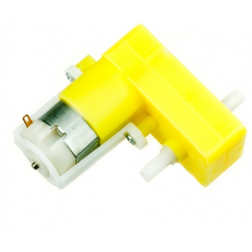
Brushed DC Motors, such as the ones used in the two wheeled and four wheeled platforms (see Figure 7-2) are the most common type used with Arduino robots. These have two leads connected to brushes (contacts) that control the magnetic field of the coils that drive the motor core (armature). Motor direction can be reversed by reversing the polarity of the power source. These motors typically rotate too fast to directly drive the robot wheels or tracks, so gear reduction is used to reduce speed and increase torque.
Other kinds of motors can be used to power robots; here are some you may come across:
- Continuous rotation servo
These motors are used on smaller robots. They have the advantage that the motor controller, motor, and gearbox are all mounted in the same housing, so they are easy to attach to a robot and can be driven directly from Arduino pins. However they usually have less torque than typical stand-alone brushed motors.
- Brushless motors
These have increased torque and efficiency compared to brushed motors but they are more expensive and complex to control. However, prices are dropping and they are a good choice for a larger robot.
- Stepper motors
These motors are used on large robots when precise control is required. These motors typically require 12 or 24 volts so they are not often used on small battery operated robots. However they may become more popular due to the recent availability of low cost 5 volt steppers.
The two wheel and four wheel platforms use small DC motors that are controlled using an H-Bridge. The H-Bridge featured in this book is part of the AFMotor shield from Adafruit Industries. This can drive up to four motors independently, although only two are used with the two wheeled robot. This shield requires a library for interfacing sketch code with the hardware; this library is included with the code download for this book (see How to Contact Us).
Note
The name H-bridge derives from the characteristic shape that you can see in these figures.
To enable the sketches to work with other H-Bridge hardware, a library named
RobotMotor is provided with the example code that provides generic
control functions that the library translates into the specific commands for the AFMotor
shield or another shield if you have use different hardware. see Software Architecture for Robot Mobility
Note
This library is modified from the one on the Adafruit site to work with the Leonardo board. The standard Adafruit library can be used with the Uno board). See Installing Third-Party Libraries if you need directions for installing a library. If you followed along with Chapter 6, you will already have the library installed.
The following diagrams explain how an H-bridge works and the RobotMotor
functions used to control the motors:
sidebyside:
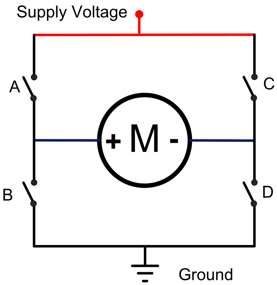
Figure 7-3 is a schematic drawing that shows how an H-bridge works. The motor is connected to the positive supply voltage and ground through four switches (in the actual H-bridge, the switching is done with transistors). When all the switches are open, no current flows and the motor is stopped. The code to stop a motor is:
motorStop(motor);
Note
The parameter in brackets (motor)
is a constant identifying the motor (MOTOR_LEFT or MOTOR_RIGHT )
to control. The software for the four wheeled robot treats the two motors on the same
side as if they were a single motor.
sidebyside:
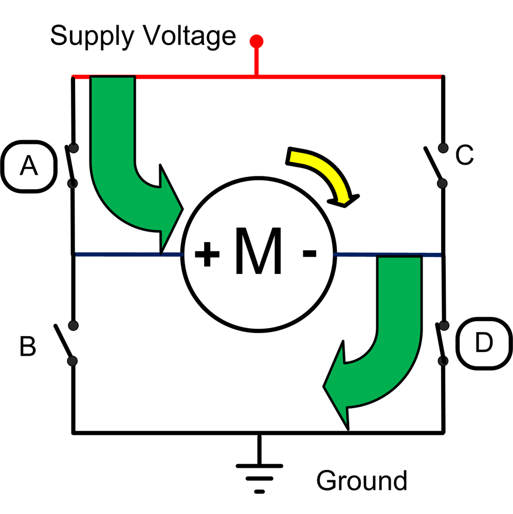
Figure 7-4 shows the two switches that when closed will cause the motor to run forward. The one marked A connects the positive motor terminal to the positive power supply. Switch D connects the negative motor terminal to ground. The code to run a motor forward at the given speed is:
motorForward(motor, speed);
Note
The constant speed is a value representing speed as a percent of maximum
speed. This is described in the section: Controlling Motor Speed.
sidebyside:
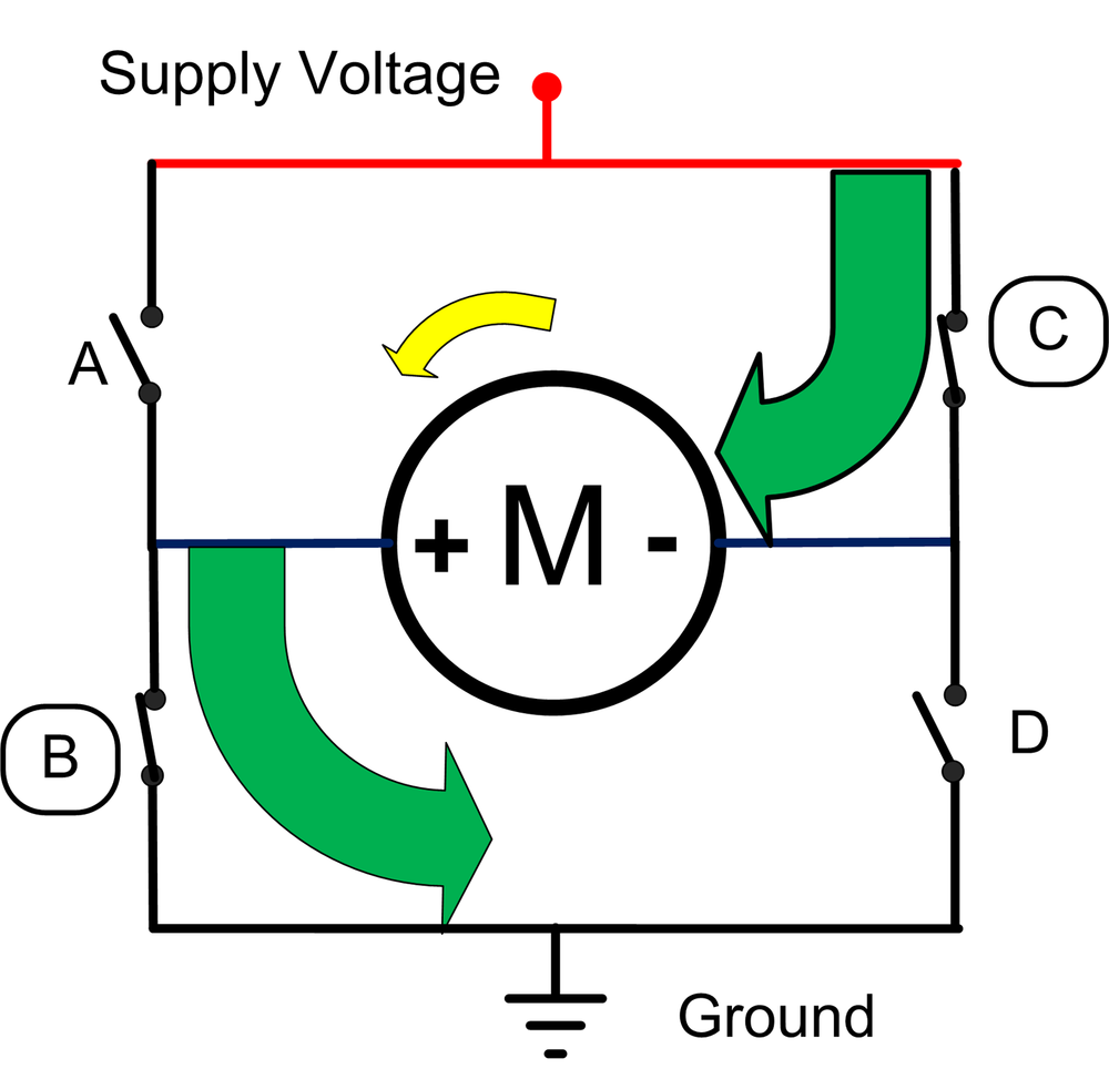
Figure 7-5 shows that the opposite switches result in the motor reversing. Switch C connects the positive supply to the negative motor terminal. Switch B connects the positive motor terminal to ground. The code to run a motor in reverse at the given speed is:
motorReverse(motor, speed);
sidebyside:
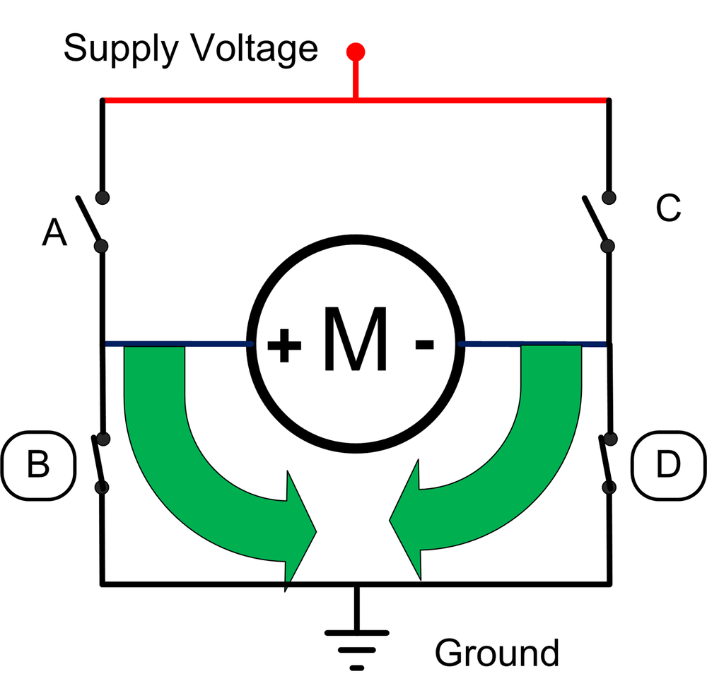
Figure 7-6 shows switches B and D closed. Both motor terminals are connected together - neither terminal is connected to the positive supply voltage. This is a mode supported by some H-bridge hardware to stop the motor more quickly than it would in the previous case where the motor is simply disconnected from the power. Because the motor terminals are shorted, the motor will resist rotation. If the motor had been spinning and then set to this mode, it will stop more quickly than if the terminals were simply disconnected. The code to brake a motor is:
motorBrake(motor);
Note
Not all H-bridges, including the Adafruit library, support this mode. The
RobotMotor library will call motorStop when the
motorBrake function is called.
Motor speed is controlled by a technique called Pulse Width Modulation (PWM), which varies the proportion of the motors on-time to-off time. The higher the proportion of on-time, the greater the motor power and the faster the robot will move (see Figure 7-7).
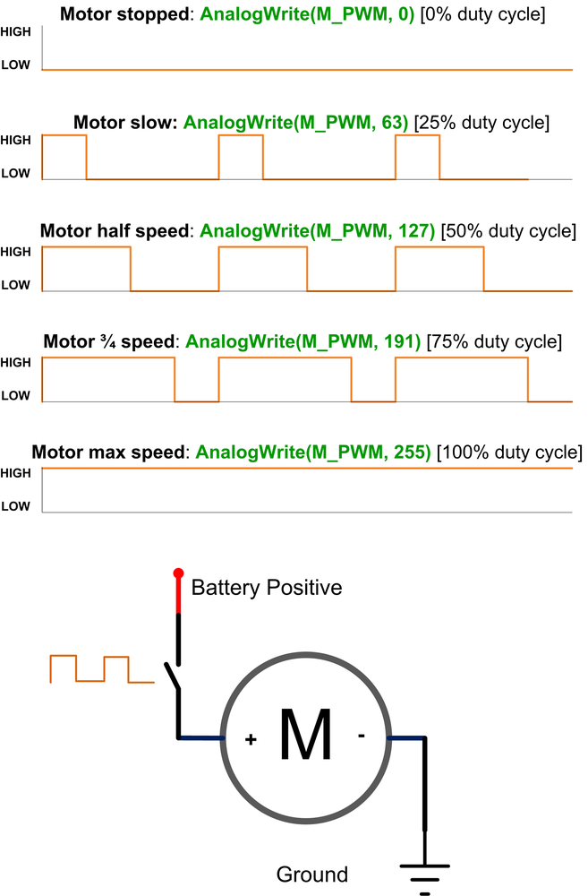
All the code in this book uses a percent value to refer to speed. This value is the percentage of power given to the motors (technically, its called the duty cycle). Percent speed is used instead of the raw PWM value to isolate the sketch logic from the low level motor code. Different motor hardware use various techniques for controlling motor rotation speed. For example, continuous rotation servos can use servo angle (where 90 is stop and 0 actually rotates the motor at full reverse speed), and stepper motors don't use PWM to control speed. Because the high level logic always uses percent and this is mapped to the range needed by the hardware in the motor interface code, the same high level code can be used with other hardware simply by swapping the appropriate motor interface module.
The AFMotor library that interfaces with the motor hardware expects a PWM value ranging
from 0 to 255, so the motorSetSpeed function in the RobotMotor library converts the percent into a
PWM value using the map function, as shown in Example 7-1.
Example 7-1. Setting the motor speed; from RobotMotor.cpp
void motorSetSpeed(int motor, int speed)
{
  motorSpeed[motor] = speed;           // save the value
  int pwm = map(speed, 0,100, 0,255);  // scale to PWM range

  motors[motor].setSpeed(pwm) ;
}
Note
map is a handy function that is used extensively throughout this
book. The function scales a value from one range to another range. For example, the
following scales a value from analogRead (0-1023) to a percent (0-100):
int toPercent = map(val, 0,1023, 0,100);
You can read more about map here: http://arduino.cc/en/Reference/map.
Bear in mind that the speed percentage is actually controlling motor power and this is usually not directly proportional to speed, particularly at low power. The amount of power required to get the robot moving is dependent on the motor, gearbox, battery voltage, robot weight and the surface the robot is on. The method to calibrate the robot will be described shortly, but first, here is an explanation of how the software handles robot speed control.
The code fragment shown in Example 7-2 contains the constants that are used to calculate the appropriate
delays for different speeds to rotate the robot. rotationTime stores the
duration for a 360 degree rotation for all practical speeds. Speeds less than
MIN_SPEED (40%) do not provide sufficient power to overcome friction in
the drive system.
Example 7-2. Constants for the delays needed to rotate the robot, from RobotMotor.cpp
const int MIN_SPEED = 40; // first table entry is 40% speed
const int SPEED_TABLE_INTERVAL = 10; // each table entry is 10% faster speed
const int NBR_SPEEDS =  1 + (100 - MIN_SPEED)/ SPEED_TABLE_INTERVAL;

int speedTable[NBR_SPEEDS]  =  {40,     50,   60,   70,   80,   90,  100}; // speeds
int rotationTime[NBR_SPEEDS] = {5500, 3300, 2400, 2000, 1750, 1550, 1150}; // time
The table holds durations in milliseconds for speeds in intervals of 10%. The values were
derived from experimentation with the two wheeled robot using a sketch named myRobotCalibrateRotation
sketch and noting the angles for each of the speeds as shown in Figure 7-8.
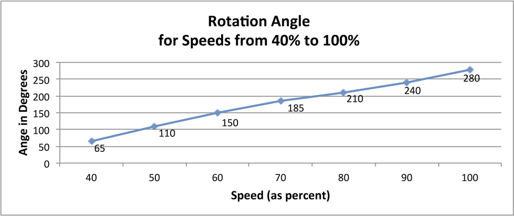
By calculating the angle as a fraction of 360 degrees, the time to rotate the robot one
complete revolution can be determined for each speed ( the calculation for the value in
milliseconds is: 1000*(360/angle).
Figure 7-9 shows the actual times for the 2WD robot.
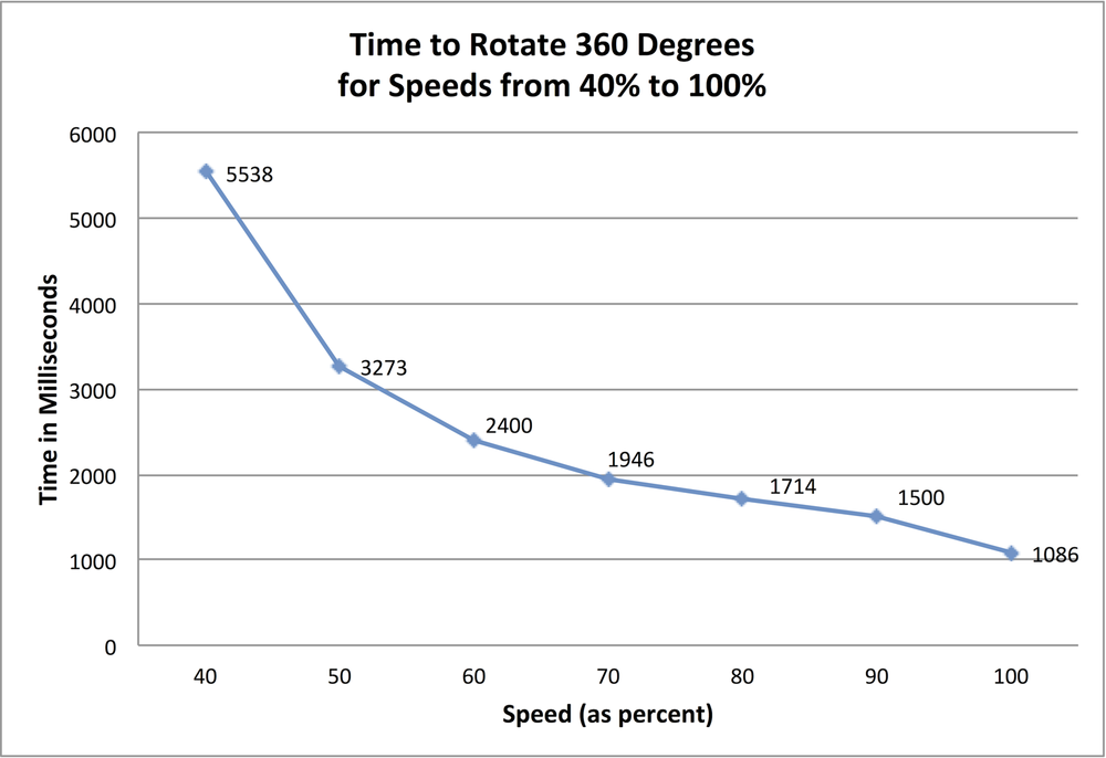
The relationship between rotation angle and speed percentage is not linear, so interpolation is used to calculate the duration to produce a full rotation for any speed (as long as it is as fast or faster than the minimum speed).
Example 7-3 shows the code that uses the table with times based on the data shown in Figure 7-9.
The RobotMotor library has the code to determine how much time the robot requires to rotate 360 degrees. This will differ between the two and four wheeled chassis and vary as the motor speed varies. Example 7-3 shows the values used in the RobotMotor.cpp code for the 2WD chassis.
Example 7-3. Controlling rotation rate
// tables hold time in ms to rotate robot 360 degrees at various speeds
// this enables conversion of rotation angle into timed motor movement
// The speeds are percent of max speed
// Note: low cost motors do not have enough torque at low speeds so
// the robot will not move below this value
// Interpolation is used to get a time for any speed from MIN_SPEED to 100%

const int MIN_SPEED = 40; // first table entry is 40% speed
const int SPEED_TABLE_INTERVAL = 10; // each table entry is 10% faster speed
const int NBR_SPEEDS =  1 + (100 - MIN_SPEED)/ SPEED_TABLE_INTERVAL;

int speedTable[NBR_SPEEDS]  =  {40,     50,   60,   70,   80,   90,  100}; // speeds
int rotationTime[NBR_SPEEDS] = {5500, 3300, 2400, 2000, 1750, 1550, 1150}; // time
Example 7-4 shows the values for the 4WD chassis.
Example 7-4. Controlling rotation rate
const int MIN_SPEED = 60; // first table entry is 60% speed
const int SPEED_TABLE_INTERVAL = 10; // each table entry is 10% faster speed
const int NBR_SPEEDS =  1 + (100 - MIN_SPEED)/ SPEED_TABLE_INTERVAL;

int speedTable[NBR_SPEEDS]  =  {60,   70,   80,   90,  100}; // speeds
int rotationTime[NBR_SPEEDS] = {5500, 3300, 2400, 2000, 1750}; // time
Note that there are fewer entries in the tables for the 4WD robot because this chassis requires a higher speed to get going. Calibrating Rotation and Tracking explains how to adjust the tables to suit your robot.
The table entries assume speed intervals of 10% so the value for MIN_SPEED should be multiple of 10. There must be one rotation time per speed so if you increase MIN_SPEED by 10 for example, you will also need to remove the first element in both speedTable and rotationTime.
The code in RobotMotor.cpp that uses the data in the rotationTime table is the same for both chassis (see Example 7-5).
Example 7-5. Applying the rotationTime table
// return the time in milliseconds to turn the given angle at the given speed
long rotationAngleToTime( int angle, int speed)
{
int fullRotationTime; // time to rotate 360 degrees at given speed

  if(speed < MIN_SPEED)
    return 0; // ignore speeds slower then the first table entry

  angle = abs(angle);

  if(speed >= 100)
    fullRotationTime = rotationTime[NBR_SPEEDS-1]; // the last entry is 100%
  else
  {
    int index = (speed - MIN_SPEED) / SPEED_TABLE_INTERVAL ; // index into speed
                                                             // and time tables
    int t0 =  rotationTime[index];
    int t1 = rotationTime[index+1];    // time of the next higher speed
    fullRotationTime = map(speed,
                           speedTable[index],
                           speedTable[index+1], t0, t1);
    // Serial.print("index= ");  Serial.print(index);
    // Serial.print(", t0 = ");  Serial.print(t0);
    // Serial.print(", t1 = ");  Serial.print(t1);
  }
  // Serial.print(" full rotation time = ");  Serial.println(fullRotationTime);
  long result = map(angle, 0,360, 0, fullRotationTime);
  return result;
}
This code determines the index into the speedTable array that is
closest to (but not greater than) the desired speed. This index is stored in the variable
t0. The interpolated time will be between this value and the next index
(t1), with the rotation time calculated using the ratio of the
rotationTime value between t0 and t1 in the same proportion as the
desired speed in the speedTable. It may be easier to understand how this
works by consulting Figure 7-10.
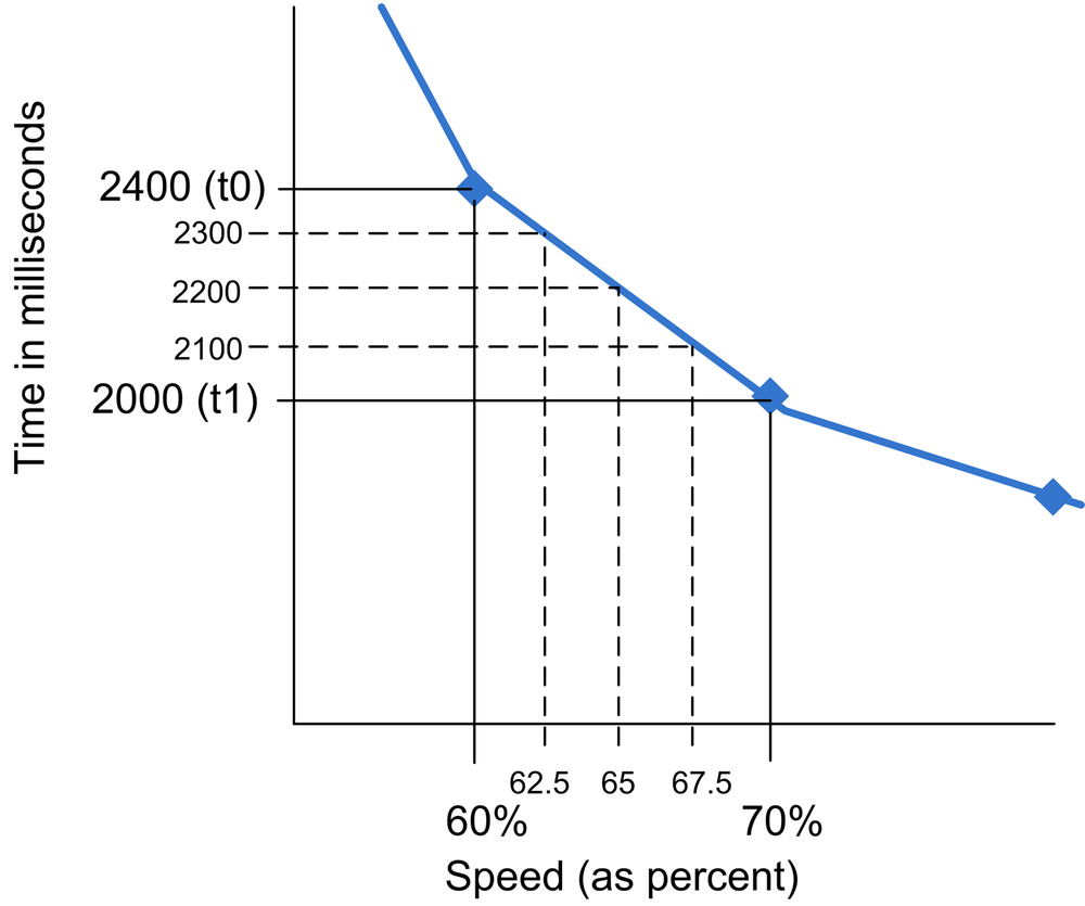
For example, for a speed of 65%, which is halfway between the values for 60% and 70%, the
time associated with 65% speed will be 2200, which is half way between 2400 (the 60% speed
value) and 2000 (the 70% speed value). A speed of 62.5% is 1/4 of the range between the table
entries (60 and 70), so the time will be 1/4 of the range between the speeds for that range
(2400 and 2000, which is 2300 milliseconds). The map function is used to
calculate this proportional value:
fullRotationTime = map(speed,speedTable[index],speedTable[index+1],t0,t1);
To calculate the time to rotate an angle other than 360 degrees, the
map function is used again:
long result = map(angle, 0,360, 0, fullRotationTime);
Motor timings do not need to be exact but if you are using the four wheeled platform you
will probably want to calibrate the values in the table because this platform requires more
rotation time than the two wheeled version. You can calibrate your robot with the
myRobotCalibrateRotation sketch. Here is the main tab for that sketch;
the actual calibration is performed in the calibrateSpeed function shown in Example 7-6.
Example 7-6. Robot calibration
/**********************************************************
MyRobotCalibrateRotation.ino
***********************************************************/
// include motor libraries
#include <AFMotor.h>     // adafruit motor shield library
#include <RobotMotor.h>  // 2wd or 4wd motor library

// Setup runs at startup and is used configure pins and init system variables
void setup()
{
  motorBegin(MOTOR_LEFT);
  motorBegin(MOTOR_RIGHT);
  calibrateSpeed();
}

void loop()
{
}

void calibrateSpeed()
{
  for(int speed = MIN_SPEED; speed <= 100; speed += 10)
  {
     // rotate robot left for 1 second
      motorReverse(MOTOR_LEFT,  speed);
      motorForward(MOTOR_RIGHT, speed);
      delay(1000); // delay 1 second
      motorStop(MOTOR_LEFT);
      motorStop(MOTOR_RIGHT);

      delay(3000);  // wait 3 seconds

      // rotate robot right for 1 second
      motorReverse(MOTOR_RIGHT,  speed);
      motorForward(MOTOR_LEFT, speed);
      delay(1000);  // delay 1 second
      motorStop(MOTOR_LEFT);
      motorStop(MOTOR_RIGHT);
      delay(3000); // wait 3 seconds
  }
}
Running this sketch will rotate the robot left (CCW) for one second, stop for one second,
then rotate the robot right (CW) for a second. If you mark the angle of the robot after each
CCW rotation, you can calculate how much longer or shorter it would take the robot to turn
360 degrees for each speed. If your robot does not rotate at all at the slower speeds, note
the lowest speed that the robot does move and set MIN_SPEED in
RobotMotor.cpp to this value.
The RobotMotor library also supports the ability to adjust the relative power to each motor in order to prevent the robot drifting off a straight course due to differences in performance between the left and right motor(s). If your robot does not track a straight line when moving forward or backward, you can modify the motor library (see next section) to correct this.
The RobotMotor.cpp library file contains a constant that can be adjusted to correct drift:
const int differential = 0; // % faster left motor turns compared to right
Here is how the differential constant is used in the code:
if( motor == MOTOR_LEFT
    && speed > differential)
    speed -= differential;
If your robot drifts, adjust the constant differential to compensate.
Set the value using trial and error, positive values nudge the robot to the right, negative
values to the left. The correct value will be the difference in speed between the motors in
percent. The drift will vary somewhat with motor speed so best to set this when testing with
the robot running at a speed midway between the minimum and maximum speeds.
Here is a modified version of the previous sketch that will drive the robot in a
straight line when the differential constant is adjusted to correct drift. You can make
differential a negative number if your right motor turns faster than your left (the robot
drifts to the left).
Example 7-7. Robot tracking
/**********************************************************
MyRobotCalibrateTracking.ino
***********************************************************/
// include motor libraries
#include <AFMotor.h>     // adafruit motor shield library
#include <RobotMotor.h>  // 2wd or 4wd motor library

const int  TEST_SPEED = MIN_SPEED + 10;   // Typical speed to run the robot
const int differential = 0;  // % faster left motor turns compared to right

// Setup runs at startup and is used configure pins and init system variables
void setup()
{
  motorBegin(MOTOR_LEFT);
  motorBegin(MOTOR_RIGHT);
  calibrateDrift();
}

void loop()
{
}

void calibrateDrift()
{
  motorForward(MOTOR_LEFT, TEST_SPEED - differential);
  motorForward(MOTOR_RIGHT,  TEST_SPEED);
  delay(2000); // delay 2 second
  motorStop(MOTOR_LEFT);
  motorStop(MOTOR_RIGHT);
}
If the robot drifts the right when running this sketch, try setting
differential to 2. If this overcorrects (the robot now drifts to the
left), decrease the differential value. If you need more correction, increase the value. If
the robot was drifting to the left, use negative values of differential to compensate. You
should be able to get the robot running more or less straight after a little trial and
error. Don't worry about minor deviations which are caused by small differences in the
efficiency of the motors at varying battery levels.
After you have settled in a value for differential you must change this in the RobotMotor.cpp file. Open this file
with a text editor and (see Modifying a Library) and find the declaration towards the beginning of the file:
const int differential = 0; // % faster left motor turns compared to right
Replace 0 with the value determined from the calibration sketch and save the file.
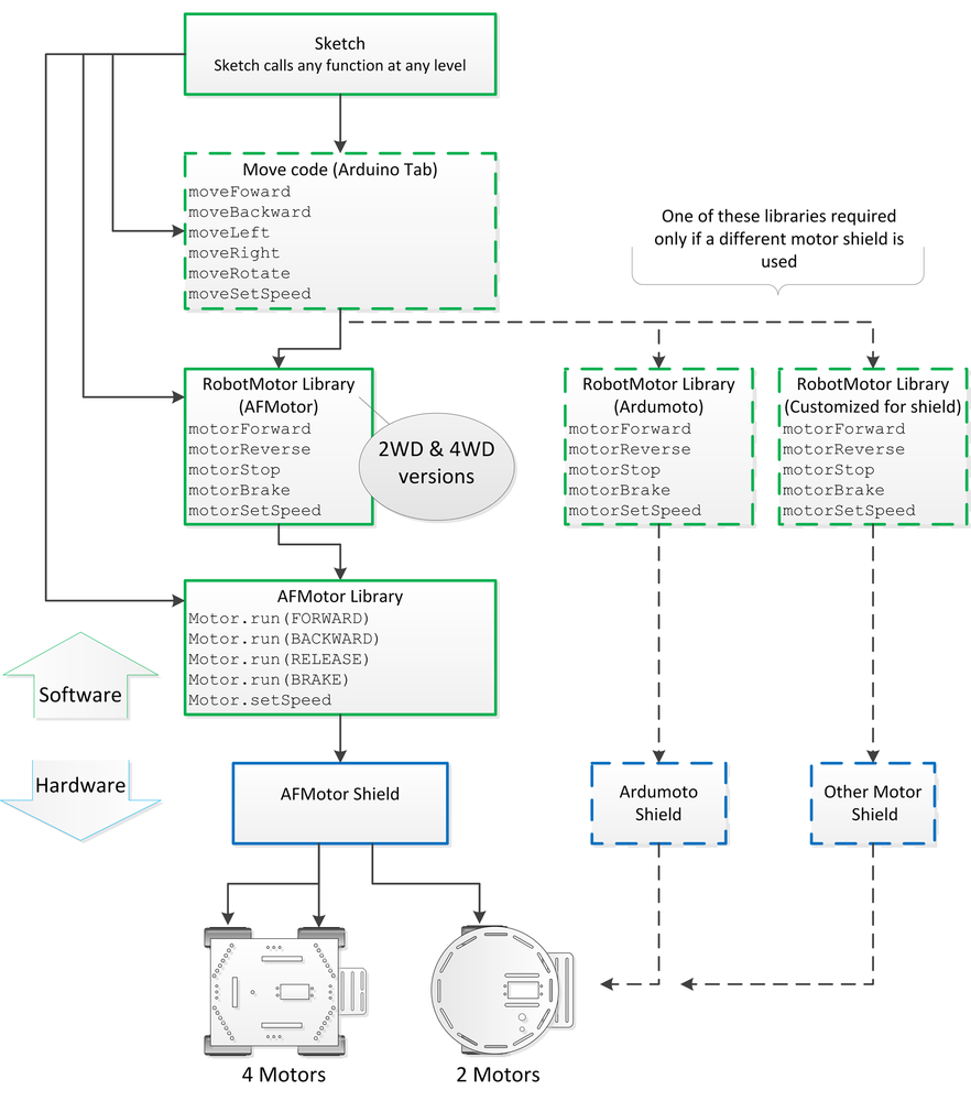
This book provides software modules to minimize the coupling between the application logic
and the hardware that actually moves the robot. This minimizes changes that would otherwise be
required if you want to use the same logic with different hardware. A low level motor
interface library named RobotMotor encapsulates the motor hardware
functions so that the same sketch code can be used with the two wheeled or four wheeled robot
with the Adafruit shield or with a different motor shield. A higher level module named
Move is also provided to enable the sketch logic to deal with robot
movements instead of motor power, for example, the Move module has commands
to move the robot left or right, to move backward, or rotate 90 degrees. Figure 7-11 shows how the software and hardware is layered. The
high level Move code is described in detail later in this chapter.
Example 7-9 shows the source code for the RobotMotor library's .cpp file. The header file
RobotMotor.h (Example 7-8) defines the constants for the left and right motors and
declares the functions for speed and direction.
Example 7-8. RobotMotor.h header file
/*******************************************************
    RobotMotor.h
    low level motor driver interface

    Copyright Michael Margolis May 8 2012
********************************************************/

/* if you have the 4WD chassis, change the line:
     #define CHASSIS_2WD
   to:
     #define CHASSIS_4WD
 */

#define CHASSIS_2WD // change suffix from 2WD to 4WD if using the 4WD chassis

// defines for left and right motors
const int MOTOR_LEFT  = 0;
const int MOTOR_RIGHT = 1;

extern const int MIN_SPEED;
extern int speedTable[];
extern int rotationTime[];
extern const int SPEED_TABLE_INTERVAL;
extern const int NBR_SPEEDS;

void motorBegin(int motor);

// speed range is 0 to 100 percent
void motorSetSpeed(int motor, int speed);

void motorForward(int motor, int speed);

void motorReverse(int motor, int speed);

void motorStop(int motor);

void motorBrake(int motor);
Example 7-9. RobotMotor functions
/*******************************************************
    RobotMotor.cpp // Adafruit version for 2WD and 4WD chassis
    low level motor driver for use with adafruit motor shield

    Motor constants used are defined AFMotor.h

    Copyright Michael Margolis May 8 2012
********************************************************/

#include <Arduino.h>
#include <AFMotor.h>  // adafruit motor shield library
#include "RobotMotor.h"


const int differential = 0; // % faster left motor turns compared to right

// tables hold time in ms to rotate robot 360 degrees at various speeds
// this enables conversion of rotation angle into timed motor movement
// The speeds are percent of max speed
// Note: low cost motors do not have enough torque at low speeds so
// the robot will not move below this value
// Interpolation is used to get a time for any speed from MIN_SPEED to 100%

// constants for 2 wheeled robot chassis
#if defined CHASSIS_2WD
const int MIN_SPEED = 40; // first table entry is 40% speed
const int SPEED_TABLE_INTERVAL = 10; // each table entry is 10% faster speed
const int NBR_SPEEDS =  1 + (100 - MIN_SPEED)/ SPEED_TABLE_INTERVAL;

int speedTable[NBR_SPEEDS]  =  {40,     50,   60,   70,   80,   90,  100}; // speeds
int rotationTime[NBR_SPEEDS] = {5500, 3300, 2400, 2000, 1750, 1550, 1150}; // time

AF_DCMotor motors[] = {
    AF_DCMotor(1, MOTOR12_1KHZ), // left is Motor #1
    AF_DCMotor(2, MOTOR12_1KHZ)  // right is Motor #2
	};
// constants for 4 wheeled robot
#elif defined CHASSIS_4WD
const int MIN_SPEED = 60; // first table entry is 60% speed
const int SPEED_TABLE_INTERVAL = 10; // each table entry is 10% faster speed
const int NBR_SPEEDS =  1 + (100 - MIN_SPEED)/ SPEED_TABLE_INTERVAL;

int speedTable[NBR_SPEEDS]  =  {60,   70,   80,   90,  100}; // speeds
int rotationTime[NBR_SPEEDS] = {5500, 3300, 2400, 2000, 1750}; // time

AF_DCMotor motors[] = {
    AF_DCMotor(4, MOTOR34_1KHZ), // left front is Motor #4
    AF_DCMotor(3, MOTOR34_1KHZ), // right front is Motor #3
    AF_DCMotor(1, MOTOR12_1KHZ), // left rear is Motor #1
    AF_DCMotor(2, MOTOR12_1KHZ)  // right rear is Motor #2
};

#else
#error "expected definition: CHASSIS_2WD or CHASSIS_4WD not found"
#endif

int  motorSpeed[2]  = {0,0}; // left and right motor speeds stored here (0-100%)

void motorBegin(int motor)
{
  motorStop(motor);  // stop the front motor
#if defined CHASSIS_4WD
  motorStop(motor+2); // stop the rear motor
#endif
}

// speed range is 0 to 100 percent
void motorSetSpeed(int motor, int speed)
{
  if( motor == MOTOR_LEFT && speed > differential)
    speed -= differential;
  motorSpeed[motor] = speed;           // save the value
  int pwm = map(speed, 0,100, 0,255);  // scale to PWM range

  motors[motor].setSpeed(pwm) ;
#if defined CHASSIS_4WD
  motors[motor+2].setSpeed(pwm) ;
#endif
}

void motorForward(int motor, int speed)
{
  motorSetSpeed(motor, speed);
  motors[motor].run(FORWARD);
#if defined CHASSIS_4WD
  motors[motor+2].run(FORWARD);
#endif
}

void motorReverse(int motor, int speed)
{
  motorSetSpeed(motor, speed);
  motors[motor].run(BACKWARD);
#if defined CHASSIS_4WD
  motors[motor+2].run(BACKWARD);
#endif
}

void motorStop(int motor)
{
  // todo set speed to 0 ???
  motors[motor].run(RELEASE);      // stopped
#if defined CHASSIS_4WD
  motors[motor+2].run(RELEASE);
#endif
}

void motorBrake(int motor)
{
  motors[motor].run(BRAKE);      // stopped
#if defined CHASSIS_4WD
  motors[motor+2].run(BRAKE);
#endif
}
The RobotMotor.cpp file contains code for both the two wheel and four
wheel chassis. Conditional compilation is used to build the library for the appropriate
version. #if defined CHASSIS_2WD and #if defined
CHASSIS_4WD are checks to see which chassis has been defined in the
RobotMotor.h file. code between #if defined
CHASSIS_2WD and #endif will only be compiled if
CHASSIS_2WD is defined in RobotMotor.h. See Installing Third-Party Libraries for more details on changing the define for the
four wheel chassis.
This library can be modified to support different hardware. For example, see Appendix B for the code to use the Ardumoto shield (but note that Ardumoto only supports two motors so is not suitable for the four wheeled robot).
You can simplify your code for controlling your robot's behaviour by using higher level movement functions provided in the Move module. These functions reference the desired movement from the robot's perspective rather than specific motor control. For example, to rotate the robot, rather than calling functions to run one motor forwards and the other backwards, you can call a single function that rotates the robot. And by calibrating the speed of rotation, you can easily get the robot to rotate to any desired angle.
The sketch named myRobotMove has the movement code in a tab called
Move. That sketch is similar to the myRobot sketch from Making the Sketch Easy to Enhance but uses the rotation functions in the Move tab to drive
the robot. Using the higher level functions to drive the robot not only simplifies your code,
it isolates the sketch logic from the hardware specific motor code. The sketches in all of the
following chapters control robot movement through the functions in the Move tab.
Here is a list of the core movement functions:
- Move Forward
Both motors are driven forward at the same speed
- Move Backward
Both motors driven in reverse at the same speed
- Move Left
Left motor stopped, right motor driven forward
- Move Right
Right motor stopped, Left motor driven forward
- Move Stop
Both motors stopped
- Set Move Speed
Used to set the speed for future robot movements
Example 7-10 shows the code in the Move tab that provides the core movement functionality.
Example 7-10. The core movement functions
/*************************************
 Drive: mid level movement functions
*************************************/

int moveState = MOV_STOP;   // what robot is doing

int  moveSpeed   = 0; // move speed stored here (0-100%)
int  speedIncrement = 10; // percent to increase or decrease speed

void moveBegin()
{
   motorBegin(MOTOR_LEFT);
   motorBegin(MOTOR_RIGHT);
   moveStop();
}

void moveLeft()
{
  motorForward(MOTOR_LEFT,  0);
  motorForward(MOTOR_RIGHT, moveSpeed);
  changeMoveState(MOV_LEFT);
}

void moveRight()
{
  motorForward(MOTOR_LEFT,  moveSpeed);
  motorForward(MOTOR_RIGHT, 0);
  changeMoveState(MOV_RIGHT);
}

void moveStop()
{
  motorStop(MOTOR_LEFT);
  motorStop(MOTOR_RIGHT);
  changeMoveState(MOV_STOP);
}

void moveBrake()
{
  motorBrake(MOTOR_LEFT);
  motorBrake(MOTOR_RIGHT);
  changeMoveState(MOV_STOP);
}

void moveBackward()
{
  motorReverse(MOTOR_LEFT, moveSpeed);
  motorReverse(MOTOR_RIGHT, moveSpeed);
  changeMoveState(MOV_BACK);
}

void moveForward()
{
  motorForward(MOTOR_LEFT,  moveSpeed);
  motorForward(MOTOR_RIGHT, moveSpeed);
  changeMoveState(MOV_FORWARD);
}

void moveSetSpeed(int speed)
{
  motorSetSpeed(MOTOR_LEFT, speed) ;
  motorSetSpeed(MOTOR_RIGHT, speed) ;
  moveSpeed = speed; // save the value
}
The code provides functions that combine the individual motor commands described in
Motor Controllers. For example, the moveForward
function calls the individual functions to rotate the left and right motors in the direction
that moves the robot forward. The speed to move is set by the
moveSetSpeed function. moveSetSpeed commands the
motors to run at the desired speed and stores the speed value so the robot can resume
running at the last set speed following an evasive action needed to avoid obstacles.
Some additional functions are included in this tab that are not used in any of the
sketches in this book but are convenient if you want to slow down or speed up the robot, for
example with remote control. The moveSlower and
moveFaster functions can be used to command the robot to decrease or
increase speed:
Example 7-11. Functions to speed up or slow down the robot
void moveSlower(int decrement)
{
   Serial.print(" Slower: ");
   if( moveSpeed >= speedIncrement + MIN_SPEED)
     moveSpeed -= speedIncrement;
   else moveSpeed = MIN_SPEED;
   moveSetSpeed(moveSpeed);
}

void moveFaster(int increment)
{
  Serial.print(" Faster: ");
  moveSpeed += speedIncrement;
  if(moveSpeed > 100)
     moveSpeed = 100;
  moveSetSpeed(moveSpeed);
}

int moveGetState()
{
 return moveState;
}

// this is the low level movement state.
// it will differ from the command state when the robot is avoiding obstacles
void changeMoveState(int newState)
{
  if(newState != moveState)
  {
    Serial.print("Changing move state from "); Serial.print( states[moveState]);
    Serial.print(" to "); Serial.println(states[newState]);
    moveState = newState;
  }
}
The moveFaster function increases the current speed by a specified
increment and calls moveSetSpeed to make this the current speed. For
example, movefaster(10); will result in the robot moving at 85% speed if
it was previously moving at 75%.
The moveSlower function is similar but decreases rather than
increases the speed. Both functions check to ensure that the new speed is valid. If
moveSlower(20) was called when the robot was moving at 85% speed, the
robot would slow down to run at 65% speed.
The movement functions also call the function changeMoveState to
store the current movement state. These states are defined in the
robotDefines.h tab (see Example 6-9) and are used to
enable the robot to make decisions with the knowledge of what it is currently doing. For
example, detecting an obstacle in front can be handled differently depending on whether the
robot is moving forwards or backwards. The robot can check the current move state when it
encounters an object and take action if the robot is moving towards it but ignore obstacles
that are not in the direction of movement. Here are all the move
states:
enum {MOV_LEFT, MOV_RIGHT, MOV_FORWARD,
      MOV_BACK, MOV_ROTATE, MOV_STOP};
Note
If you are unfamiliar with enum (enumerated lists), see Code Style (About the Code) in Preface or an online C or C++ reference.
To assist debugging, each state has an associated text label that can be printed to the serial monitor to show what the robot should be doing.
const char* states[] = {"Left", "Right", "Forward",
                        "Back", "Rotate", "Stop"};
The move state defines are located at the end of the robotDefines.h
tab.
Rotation is a common task as the robot is exploring and moving to avoid obstacles. The robots described in this book do not know the angle they are facing or how much actual movement results from driving the motors. Commands to rotate the robot at particular angle are implemented by timing how long to turn the motors based on data collected during calibration. Example 7-12 shows the rotation functions from the Move tab:
- Move Rotate
One motor forward, one reverse for the duration to rotate the robot to the given angle. Positive angles rotate clockwise, negative angles counter-clockwise
- Rotation Angle to Time
Function used to calculate the duration to rotate the robot to a given angle at a given speed. This function is the same as listed in Load and Run helloRobot.ino
- Calibrate Rotation Rate
Function used for calibration—the robot will attempt to rotate at a given angle at speeds from minimum speed up to 100% at intervals of 10%. This function is the same as listed in Load and Run helloRobot.ino
Example 7-12. Functions to rotate the robot
void moveRotate(int angle)
{
  Serial.print("Rotating ");  Serial.println(angle);
  if(angle < 0)
  {
    Serial.println(" (left)");
    motorReverse(MOTOR_LEFT,  moveSpeed);
    motorForward(MOTOR_RIGHT, moveSpeed);
    angle = -angle;
	changeMoveState(MOV_ROTATE);
  }
  else if(angle > 0)
  {
    Serial.println(" (right)");
    motorForward(MOTOR_LEFT,  moveSpeed);
    motorReverse(MOTOR_RIGHT, moveSpeed);
    changeMoveState(MOV_ROTATE);
  }
  int ms = rotationAngleToTime(angle, moveSpeed);
  movingDelay(ms);
  moveBrake();
}

// return the time in milliseconds to turn the given angle at the given speed
long rotationAngleToTime( int angle, int speed)
{
int fullRotationTime; // time to rotate 360 degrees at given speed

  if(speed < MIN_SPEED)
    return 0; // ignore speeds slower then the first table entry

  angle = abs(angle);

  if(speed >= 100)
    fullRotationTime = rotationTime[NBR_SPEEDS-1]; // the last entry is 100%
  else
 {
    int index = (speed - MIN_SPEED) / SPEED_TABLE_INTERVAL; // index into speed and time tables
    int t0 =  rotationTime[index];
    int t1 = rotationTime[index+1];    // time of the next higher speed
    fullRotationTime = map(speed,  speedTable[index],  speedTable[index+1], t0, t1);
   // Serial.print("index= ");  Serial.print(index); Serial.print(", t0 = "); Serial.print(t0);
   // Serial.print(", t1 = ");  Serial.print(t1);
 }
 // Serial.print(" full rotation time = ");  Serial.println(fullRotationTime);
  long result = map(angle, 0,360, 0, fullRotationTime);
  return result;
}


// rotate the robot from MIN_SPEED to 100% increasing by SPEED_TABLE_INTERVAL
void calibrateRotationRate(int direction, int angle)
{
  Serial.print(locationString[direction]);
  Serial.println(" calibration" );
  for(int speed = MIN_SPEED; speed <= 100; speed += SPEED_TABLE_INTERVAL)
  {
    delay(1000);
    //blinkNumber(speed/10);

    if( direction == DIR_LEFT)
    {    // rotate left
      motorReverse(MOTOR_LEFT,  speed);
      motorForward(MOTOR_RIGHT, speed);
    }
    else if( direction == DIR_RIGHT)
    {    // rotate right
      motorForward(MOTOR_LEFT,  speed);
      motorReverse(MOTOR_RIGHT, speed);
    }
    else
       Serial.println("Invalid direction");


    int time = rotationAngleToTime(angle, speed);

    Serial.print(locationString[direction]);
    Serial.print(": rotate ");           Serial.print(angle);
    Serial.print(" degrees at speed ");  Serial.print(speed);
    Serial.print(" for ");               Serial.print(time);
    Serial.println("ms");
    delay(time);
    motorStop(MOTOR_LEFT);
    motorStop(MOTOR_RIGHT);
    delay(2000); // two second delay between speeds
  }
}
The moveRotate function will rotate a robot by the given angle.
Negative angles turn counter clockwise, positive angles turn clockwise. Rotation is achieved
by running the motors in opposite directions (see How Robots Move).
Higher level movement functions work together to provide a simple way to instruct the robot briefly move away from one obstacle while checking to see if it needs to avoid another obstacle encountered while taking evasive action.
- Timed Move
Moves the robot in a specified direction for a specified duration.
- Moving Delay
Checks for obstacles while delaying for a specified period. Uses
checkMovement()function in theLookmodule to see if an obstacle is detected in the current direction of movement.
Example 7-13. Higher level movement functions
/************* high level movement functions ****************/

//moves in the given direction at the current speed for the given duration in milliseconds
void timedMove(int direction, int duration)
{
  Serial.print("Timed move ");
  if(direction == MOV_FORWARD) {
    Serial.println("forward");
    moveForward();
  }
  else if(direction == MOV_BACK) {
    Serial.println("back");
    moveBackward();
  }
  else
    Serial.println("?");

  movingDelay(duration);
  moveStop();
}

// check for obstacles while delaying the given duration in ms
void movingDelay(long duration)
{
  long startTime = millis();
  while(millis() - startTime < duration) {
     // function in Look module checks for obstacle in direction of movement
     if(checkMovement() == false) {
        if( moveState != MOV_ROTATE) // rotate is only valid movement
        {
            Serial.println("Stopping in moving Delay()");
            moveBrake();
        }
     }
  }
}
The timedMove and movingDelay functions work
together to provide a simple way to instruct the robot briefly move away from an obstacle.
Because movingDelay can check for obstacles while taking evasive action,
it can avoid bumping into new obstacles while moving away from another. The
checkMovement function is implemented in the Look module (see The Look Code).