
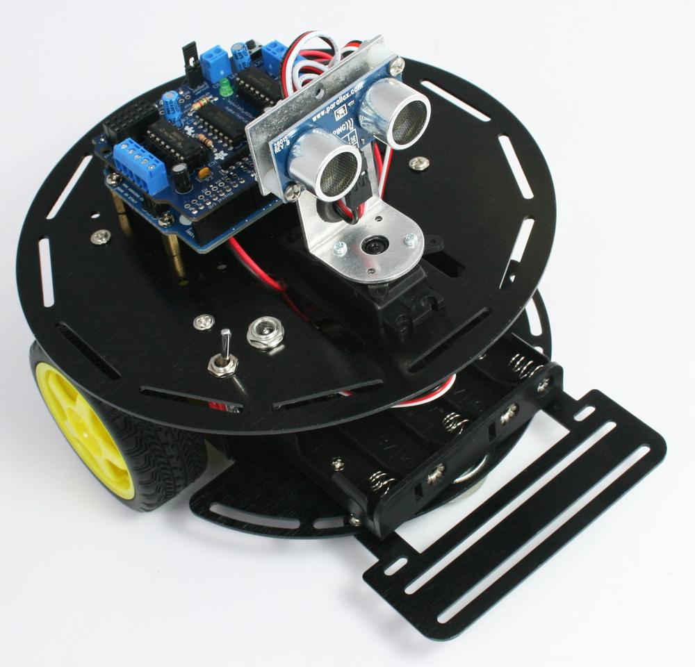
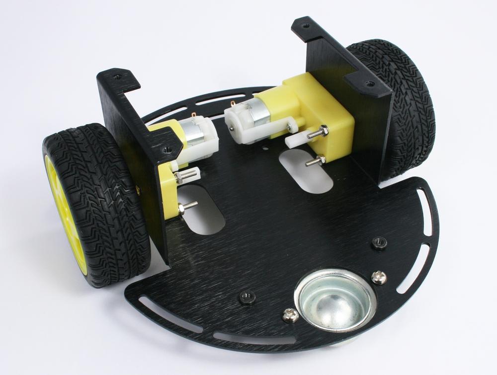
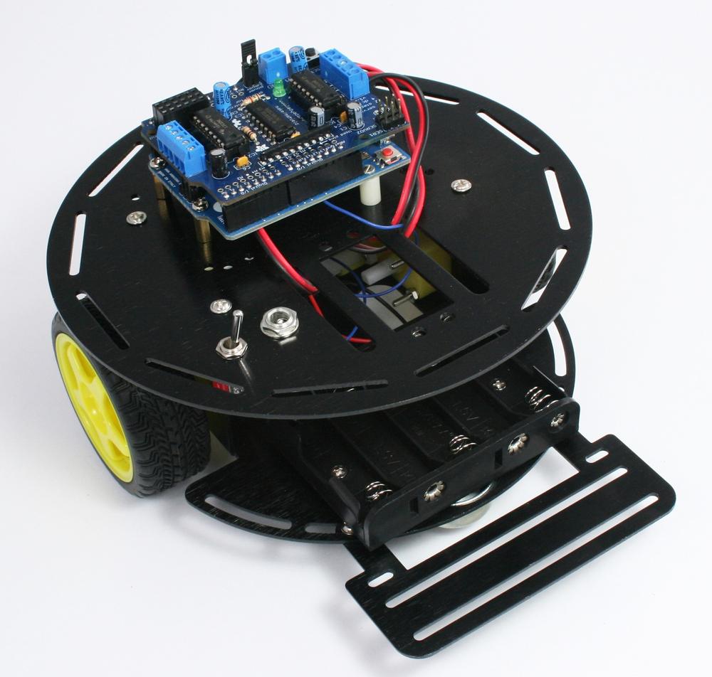
This chapter provides advice on the construction of a Two Wheel Drive (2WD) chassis with front caster, as shown in Figure 3-1. Construction is straightforward; you can follow the detailed steps or improvise if you want to customize your robot. The chapter also shows how you attach and connect sensors used in the projects covered in later chapters.
If you prefer to build a two wheeled robot of your own design, you should read the sections on attaching control electronics and sensors; this will prepare you to use the code for the projects in the chapters to come. Information in this chapter my also provide some ideas to help with the design of your own robot.
See http://shop.oreilly.com/product/0636920028024.do for a detailed parts list.
Tools listed in Tools
The assembled electronics (see Chapter 2, Building the Electronics
2WD Mobile Platform (two wheeled robot kit made by DFRobot)
Two 0.1uF ceramic capacitors
Two lengths of 3 conductor ribbon cable, two 3 way 0.1" headers for edge sensors
Optional: charging circuit resistors and diode, see detailed parts list
Figure 3-2 shows all of the parts contained in the 2WD chassis package. The three black brackets to the left of the figure are not needed for any of the projects in this book.
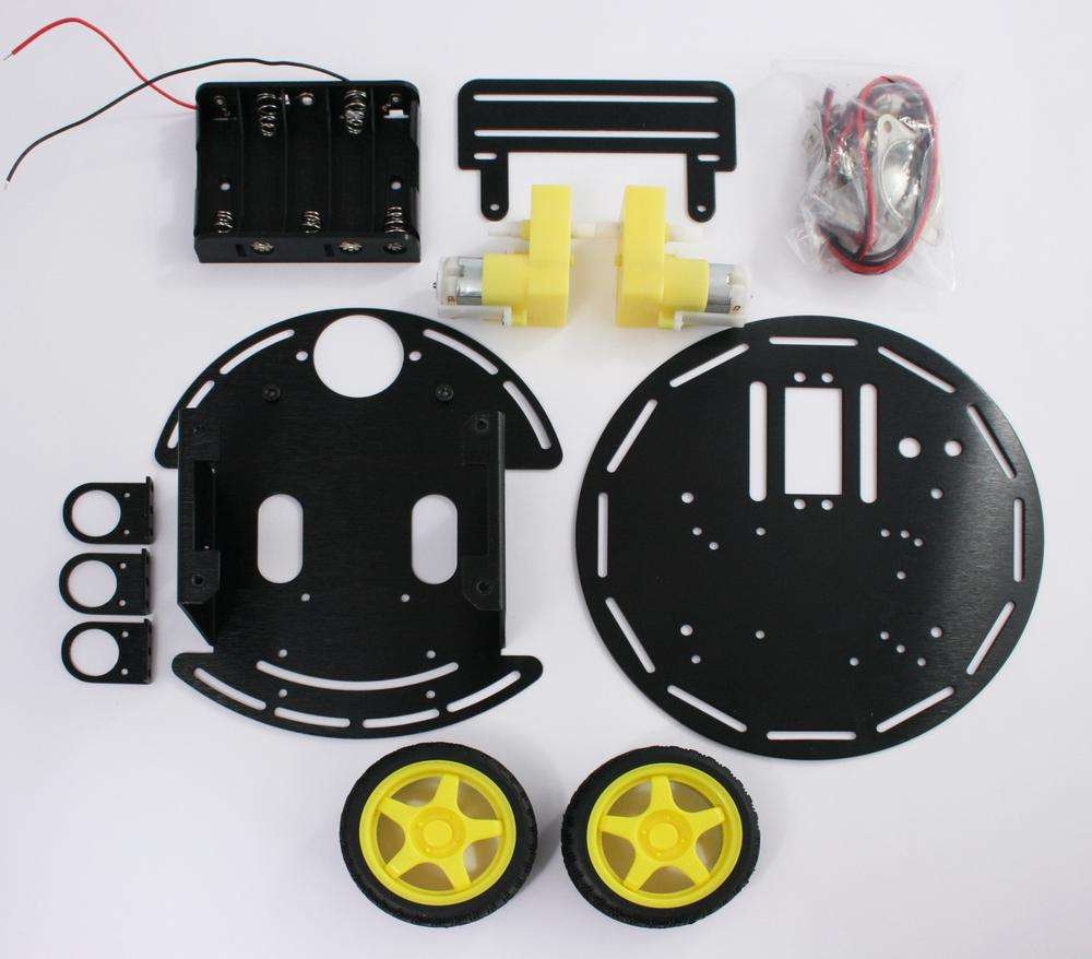
Figure 3-3 shows the contents of the bag containing the mounting hardware. Locate the two bolts with the flat heads and put them aside for mounting the battery case. Also identify the two thicker (M4) bolts that will be used to attach the caster. The remaining short bolts in this pack are identical.

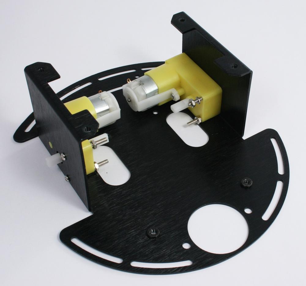
Use two long bolts with lock washers and nuts, as shown in Figure 3-5, to attach each motor to the chassis lower plate. Tighten the nuts snugly but take care not to stress the plastic motor housing.
Note
Lock washers are used to prevent a nut from accidentally coming lose due to vibration. This is particularly important for attaching the motor and switch. These washers have a split ring or serrations that apply extra friction when tightened.
If you find that things still come lose, don't overtighten the nuts; an effective solution is retighten the nut and apply a dab of nail polish to the point where the threads emerge from the nut.
Figure 3-4 shows the motors in place with the nut seen on the upper right ready to be tightened.

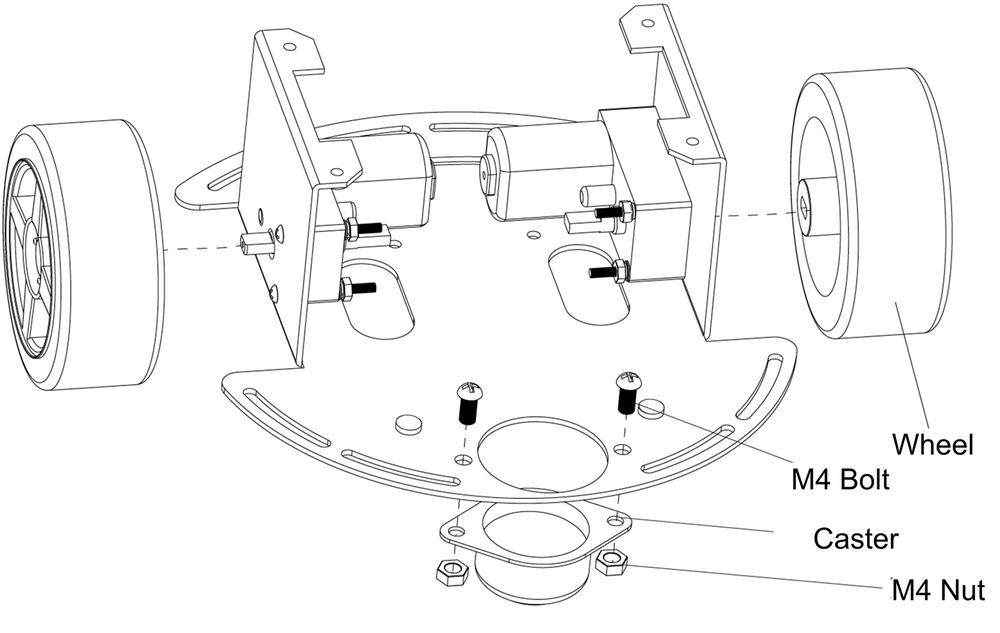
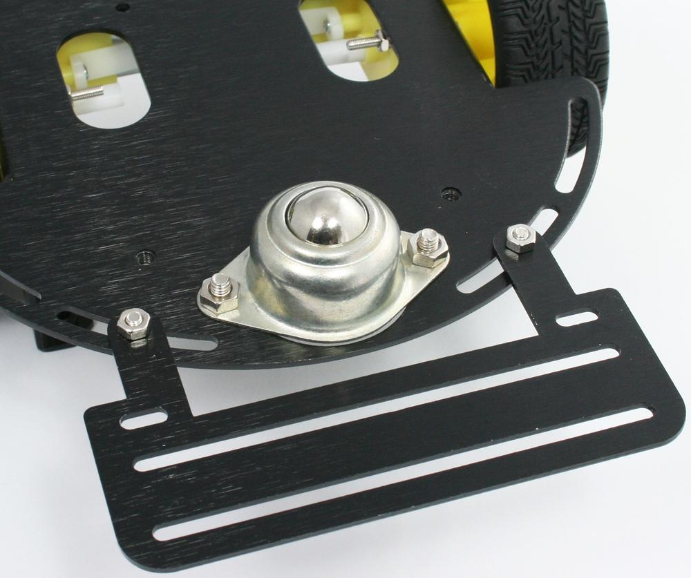
Push the wheels onto the motor assembly shafts, aligning the slots in the wheels with the flat section of the motor shaft. Attach the caster with two M4 bolts and nuts. Figure 3-6 and Figure 3-7 show this.
Attach the sensor bracket to the underside of the lower chassis plate, as seen in Figure 3-8 and Figure 3-9.
Note
This robot is sometimes built with the sensor plate mounted at the opposite end of the chassis (furthest from the caster). You can build yours however you like, but the orientation shown here enables the servo mounted distance scanner to be attached in the front of the robot. Also, the sensor bracket in this location maximizes the distance between the wheels and the line sensors and this improves line following sensitivity.
Figure 3-9 shows the underside of the chassis after mounting the sensor bracket. Note that the sensor bracket is attached to the bottom of the chassis plate.

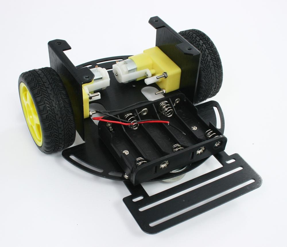
The battery pack is bolted to the bottom base plate with two countersunk (flat headed) Phillips bolts as shown in Figure 3-10 and Figure 3-11. You may want to delay this step until after the battery leads have been soldered to make it easier to position all the wires.

Cut two pieces of red/black wire, each about 7 1/2 inches long. Strip to expose about 3/16 inch of bare wire at one end of the wires and attach to the motor terminals. Strip 1/4 inch off the other end of the pairs of wires; these will be connected to the motor shield. Connect a 0.1uF capacitor across each of the motor terminals, as shown in Figure 3-12. The capacitors suppress electrical spikes generated by the motor that could interfere with signals on the Arduino board.

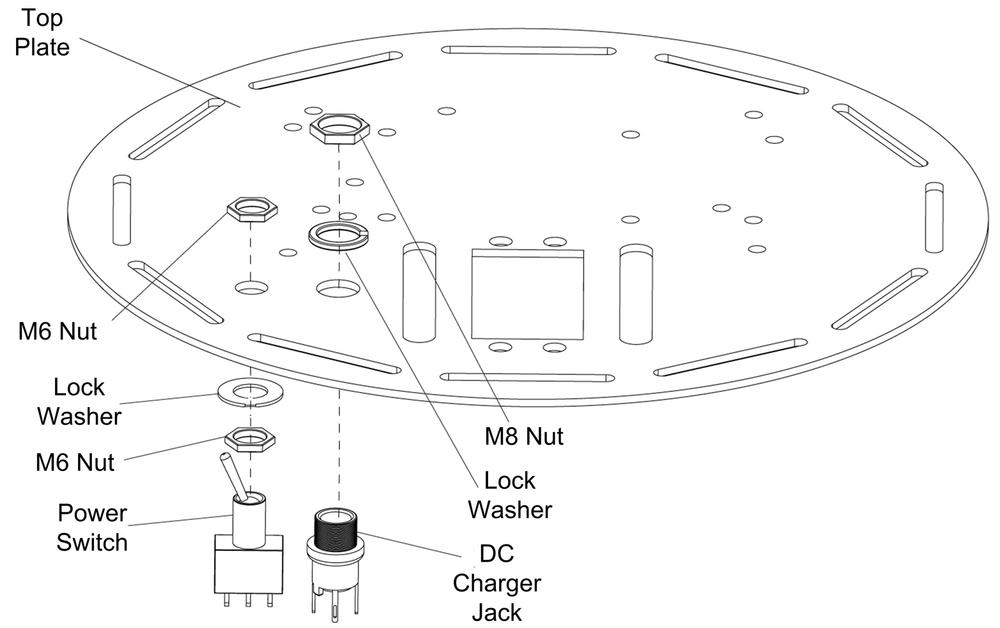
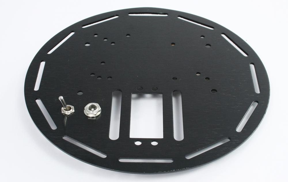
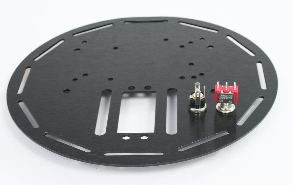
The DC power jack is bolted to the top plate using the large (M8) lock washer and nut. The switch is mounted using two (M6) nuts and a lock washer. Put one nut on the switch leaving around 3/16" of thread above the nut. Then place the lock washer on the thread and push this through the opening in the rear plate and secure with the second M6 nut.
Orient the switch so the toggle moves towards the jack, as shown in Figure 3-13 and Figure 3-14 (Figure 3-15 shows the view from beneath).
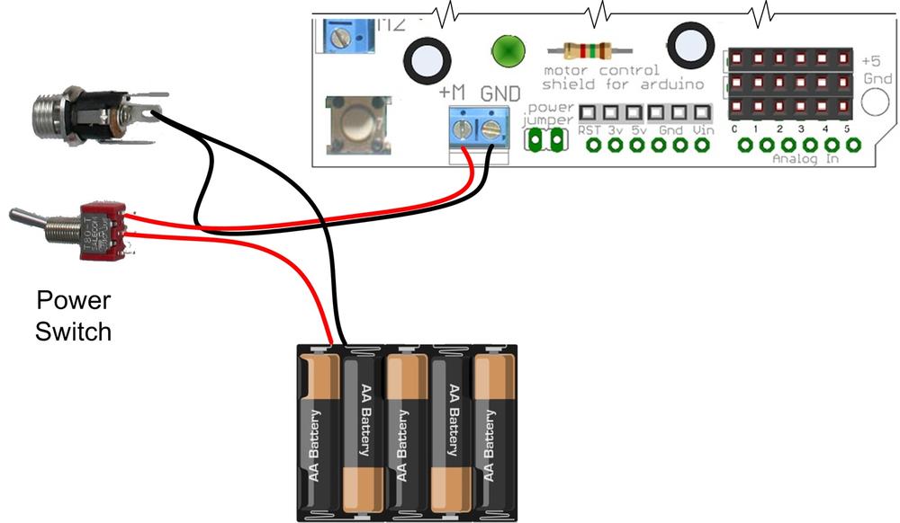
The battery can be wired as shown in Figure 3-16 and Figure 3-17. The power switch will disconnect the battery when the robot is not in use. The DC jack is not used in this configuration (other than as a junction point for the black ground wires). The switch is off when the toggle is closer to the DC jack as shown (the toggle is a lever; when the exposed end is up as seen in the figure, the contact at the bottom is connected and the contact wired to the shield is open).

You can build a simple trickle charger into the robot if you will be using rechargeable NiMH batteries. The charger can be built using the circuit shown in Figure 3-18 and Figure 3-19. See Trickle Charging for information about using the charger.


The easiest way to mount the Arduino board is with a strip of Velcro. A 2.5" x 1.5" strip is supplied with the Rovera 2W (Arduino-Controlled 2 Wheel Robotics Platform) kit. To prevent the Arduino pins from accidentally shorting to the chassis, apply insulating tape to the underside of the Arduino board. Gaffer tape works well but you can use (non-conductive) duct tape or heavy duty electrical tape. Attach the 'hairy' side of the Velcro to the taped Arduino board, the hook side is fastened as shown in Figure 3-20.

Figure 3-21 shows the mounted boards. The Velcro will hold the boards in position when the robot is moving about, but use one hand to steady the Arduino when you unplug the shield and take care not to use too much downward pressure that could push the Arduino pins through the tape when plugging in the shield.

If you prefer a more rigid mount, you can use two of the 10mm brass standoffs supplied with the chassis and two M3 bolts and nuts (seen on the right side of the board as shown in Figure 3-22). Use a 10mm spacer and M2.5 in the hole near the reset switch. (The hole near the DC jack at the lower left is not used.)
Note
The spacer is required for a Leonardo board because there is insufficient space for an M3 bolt in the munting hole near the switch. The Uno board has more room so you can use a another of the 10mm spacers and M3 hardware for mounting that board.
Figure 3-23 shows the location of the mounting points viewed from the underside of the panel.


Attach the top plate with four M3 bolts as shown in Figure 3-24.

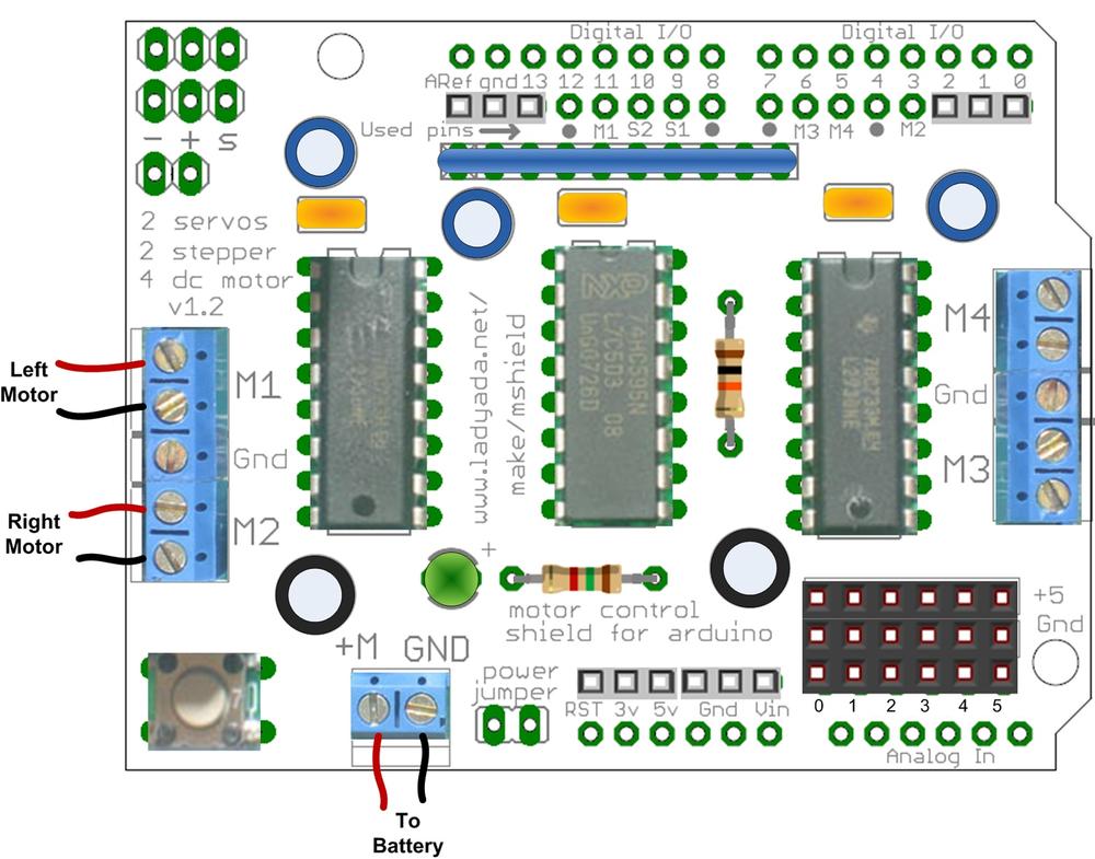
Figure 3-25 shows where the battery and motor wires are connected. Left and right are from the robot's perspective (the right wheel is the one closest to the switch). Figure 3-26 shows the main electronics in place.
This section covers mounting of the infrared (IR) reflectance sensors for use in edge detecting or line following. Infrared Reflectance Sensors explains how these sensors work and Chapter 9, Modifying the Robot to React to Edges and Lines describes how to use IR sensors. This section explains how to mount these to the 2WD platform and connect them to Arduino. The first projects in this book should have the sensors mounted as shown in the section on edge detection. When you are ready to implement the line following application in Chapter 9, refer back to the section here on positioning the sensors for line following. The stripboard mount described in Making a Line Sensor Mount simplifies the attachment and wiring of the sensors for line detection and this can also be used for edge detection, but bear in mind that the robot will perform the edge detection task best with the sensors further apart. If the sensors are close together, the robot can have difficulty determining the best angle to turn when an edge is encountered.
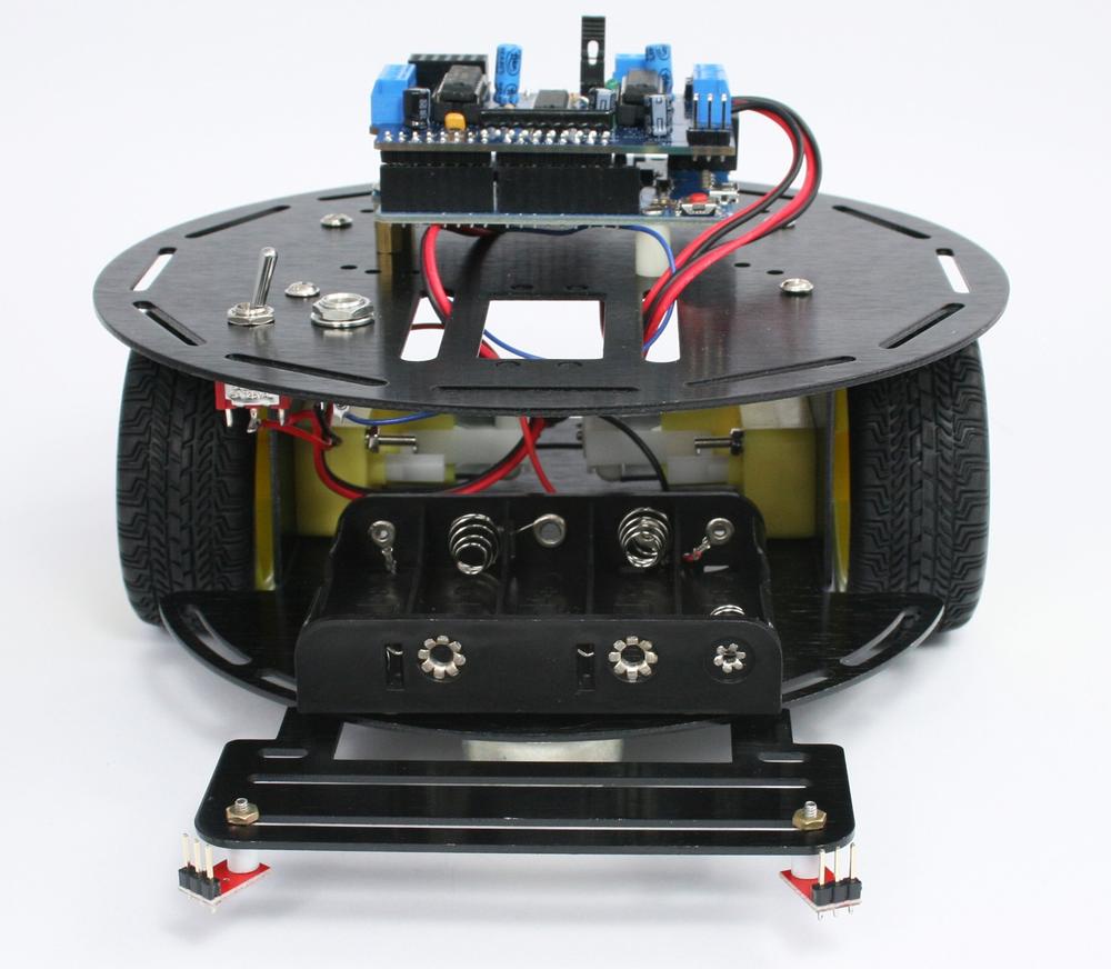
Edge detection requires two QTR-1A sensors mounted on the front of the robot. These should be spaced as widely as possible. The ideal location is with each sensor positioned in front of a wheel so an edge can be detected before a wheel would otherwise fall off a 'cliff'. However, if your priority is simplicity of construction rather than accuracy of edge detection, you can use the same mount described in the next section covering line detection.
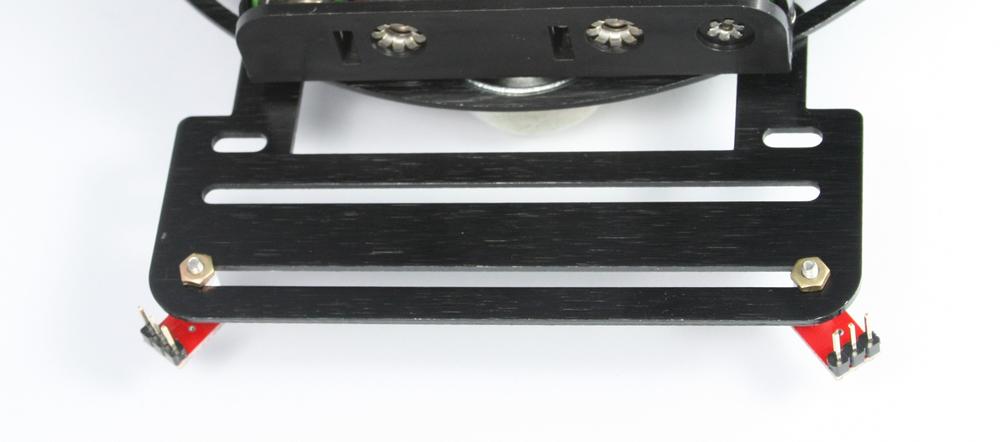
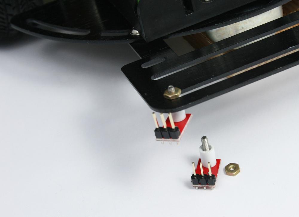
The side with the sensor faces the ground and the header pins face upwards. Mount each sensor using a 2-56 bolt and nut (M2 bolts and nuts can also be used) with a 1/2" plastic spacer so the face of the sensor is 3/8" or closer to the ground. Figure 3-27, Figure 3-28, Figure 3-29, and Figure 3-30 show suggested mounting.

Three QTR-1a sensors are required for line following. Making a Line Sensor Mount describes how to build a stripboard mount for line sensing. However, you can also mount and attach each sensors as described in this section if you want to experiment with how varying the spacing of the sensors affects line following.
The sensors can be attached using 2-56 or M2 hardware. The component side faces down and the header pins face upwards. They are mounted in the front, equally spaced with approximately 1/2 inch between the center and the left and right bolts (Figure 3-31).
If you use the stripboard mount for line sensors covered in Chapter 2, Building the Electronics, the stripboard can be mounted above or below the sensor bracket, enabling you to experiment with sensor distance to the ground—but use insulated washers to ensure that the tracks with sensor connections are not shorted to the bracket. Figure 3-32 and Figure 3-33 show how the stripboard can be mounted.


See Figure 3-27 for information on connecting the stripboard wires to the motor shield.
Chapter 5, Tutorial: Getting Started with Arduino explains how to set up and use the development environment that will be used to upload code to the robot. If you are already an Arduino expert, you can skip to Chapter 6, Testing the Robot's Basic Functions, but first, see Installing Third-Party Libraries for advice on the libraries used with the code for this book.
If you have the libraries installed and want run a simple test to verify that the motors are working correctly, you can run the sketch shown in Example 3-1.
Example 3-1. Initial motor test for 2WD
/*******************************************
* MotorTest2wd.ino
* Initial motor test for 2WD - robot rotates clockwise
* Left motor driven forward, right backward
* then counter-clockwise

* Michael Margolis 24 July 2012
********************************************/
const int LED_PIN = 13;
const int speed = 60; // percent of maximum speed

#include <AFMotor.h>  // adafruit motor shield library (modified my mm)
AF_DCMotor Motor_Left(1, MOTOR12_1KHZ);   // Motor 1
AF_DCMotor Motor_Right(2, MOTOR12_1KHZ);  // Motor 2

int pwm;

void setup()
{
  Serial.begin(9600);
  blinkNumber(8); // open port while flashing. Needed for Leonardo only

  // scale percent into pwm range (0-255)
  pwm= map(speed, 0,100, 0,255);
  Motor_Left.setSpeed(pwm);
  Motor_Right.setSpeed(pwm);
}

// run over and over
void loop()
{
  Serial.println("rotate cw");
  Motor_Left.run(FORWARD);
  Motor_Right.run(BACKWARD);
  delay(5000); // run for 5 seconds
  Serial.println("rotate ccw");
  Motor_Left.run(RELEASE);  // stop the motors
  Motor_Right.run(RELEASE);
  delay(5000); // stop for 5 seconds
}

// function to indicate numbers by flashing the built-in LED
void blinkNumber( byte number) {
   pinMode(LED_PIN, OUTPUT); // enable the LED pin for output
   while(number--) {
     digitalWrite(LED_PIN, HIGH); delay(100);
     digitalWrite(LED_PIN, LOW);  delay(400);
   }
}
This sketch runs the motors in opposite directions to cause the robot to rotate clockwise for 5 seconds, then reverses direction to rotate counter-clockwise. This will repeat until the power is switched off.