This chapter covers techniques that enable your robot to use sensors to gain awareness of its environment. Using reflectance sensors, the robot will gain the ability to follow lines or to avoid falling off the edge of the surface it is on. Information from the sensors is abstracted so that the robot logic has a single consistent interface and can easily be enhanced to support other sensors. The physical mounting of the sensors varies with different platforms: see Chapter 4, Building the Four-Wheeled Mobile Platform if you have the 4WD chassis, Chapter 3, Building the Two-Wheeled Mobile Platform if you have the 2WD chassis.
Two reflectance sensors are used for edge detection and a third is needed for line following. Although you can use the stripboard mount (for the three line following sensors) discussed in Chapter 2 to experiment with edge detection, the robot will perform the edge detection task best with the sensors further apart (the stripboard approach is best for line following). If the sensors are close together, the robot can have difficulty determining the best angle to turn when an edge is encountered.
Note
See Chapter 3, Building the Two-Wheeled Mobile Platform for details of mounting these sensors on the 2WD chassis and Chapter 4, Building the Four-Wheeled Mobile Platform for the 4WD chassis. The principles of reflectance sensors are covered in Infrared Reflectance Sensors in Chapter 8, Tutorial: Introduction to Sensors.
A reflective surface with non-reflective edges for the edge detection sketch (see Figure 9-2. You can use a large sheet of plain white paper with the edges marked using a black marker pen or black electrical tape. The border should be around 3/4 of in inch thick or so. The optimal surface would be white, but with sufficient friction that your robot won't slip. Lining paper, often sold as unpasted wall liner, is a great surface. It's designed to provide an even surface or wallpapering or painting, but with enough texture that makes it great for racing robots.
A reflective surface with a non-reflective line approximately 3/4 inch wide, see Figure 9-3. If your surface is at least a couple of feet wide, you can use the same course for edge detection and line following. The sketches have been tested using a three foot length of 27 inch wide lining paper.
myRobotEdge.inoThe robot will move about in an area bounded by a non-reflective surface (for example, a large sheet of white paper placed on a non-reflective surface. Most surfaces that reflect visible light will reflect infrared from the sensor).
myRobotLine.inoThis repositions the sensors used in
myRobotEdge.inoto allow the robot to follow black lines painted on or taped to a white surface. The only change to the tab code is support for the center sensor. A variant of this sketch that sends data over serial for display on an external serial device is namedmyRobotLineDisplayand is included in the example code download (see How to Contact Us).
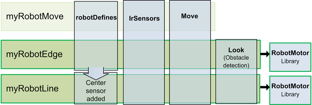
Figure 9-1 shows the organization of the modules for this chapter.
The code to look for an obstacle and return true if detected is
implemented in the function named lookForObstacle. You saw this function in
the main tab of the sketch described in Chapter 6, Testing the Robot's Basic Functions. Because this code will be extended in this and later chapters to support additional
sensors, it makes sense to extract this code into its own tab. The download code for all
sketches introduced from here on in have a tab named Look that contains
the code shown in Example 9-1.
Example 9-1. Code for the Look tab
/**********************
 code to look for obstacles
**********************/

void lookBegin()
{
  irSensorBegin();    // initialize sensors
}

// returns true if the given obstacle is detected
boolean lookForObstacle(int obstacle)
{
  switch(obstacle) {
     case  OBST_FRONT_EDGE: return irEdgeDetect(SENSE_IR_LEFT) && irEdgeDetect(SENSE_IR_RIGHT);
     case  OBST_LEFT_EDGE:  return irEdgeDetect(SENSE_IR_LEFT);
     case  OBST_RIGHT_EDGE: return irEdgeDetect(SENSE_IR_RIGHT);
  }
  return false;
}

// function to check if robot can continue moving when taking evasive action
// returns true if robot is not blocked when moving to avoid obstacles
// this 'placeholder' version always returns true
boolean checkMovement()
{
  return true;
}
As mentioned in Chapter 6, Testing the Robot's Basic Functions, the
lookForObstacle function enables you to enquire if an obstacle is
detected and will return true if so. The case statement
(see http://arduino.cc/en/Reference/SwitchCase) tries to match the
obstacle variable with one of the obstacle constants (defined in
robotDefines.h). If there is a match, the irEdgeDetect function is called with relevant sensor and this will return true if
an object is detected on that sensor. If no object is detected, the function returns OBST_NONE. The look functionality can be expanded by adding code
to the case statement and calling appropriate sensor functions, as you will see later in this
chapter.
But first, let's use the existing functionality to give the robot the ability to follow lines and detect edges.
Edge detection is one of the easier behaviors to understand and program. The robot moves until it encounters an edge; it should then change direction to avoid moving over the edge. Edges are detected by using reflectance sensors (see: Chapter 8, Tutorial: Introduction to Sensors). Typically, the edge is an area that does not reflect, for example the edge of a table.
In the sketch that follows, the robot will remain within a reflective surface (for example, a large white sheet of paper) that is bounded by a black line. Black electrical tape (3/4 inch or wider) works well but a black line of similar width drawn with magic marker or paint can also work as the 'edge'. To avoid damaging your robot, an actual table is not recommended for early experiments until you are sure you have everything working correctly.
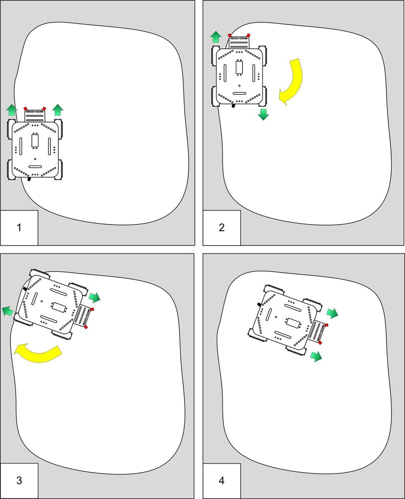
Figure 9-2 shows how the robot responds to moving over an edge. In panel1, the sensors do not detect an edge so the robot moves forward. In panel 2, the left sensor moves off the reflective surface so the robot stops and rotates 120 degrees. In panel 3, the robot completes its rotation; panel 4, shows the robot moving forward again.
Example 9-2. Main sketch code for edge detection
/******************************************************************************
myRobotEdge.ino

Robot sketch to move within area bordered by a non-reflective line

Michael Margolis 7 July 2012
******************************************************************************/
#include <AFMotor.h>  // adafruit motor shield library
#include "RobotMotor.h"    // 2wd or 4wd motor library

#include "robotDefines.h"  // these were the global defines from myRobot

/// Setup runs at startup and is used configure pins and init system variables
void setup()
{
  Serial.begin(9600);
  blinkNumber(8); // open port while flashing. Needed for Leonardo only

  lookBegin();  /// added Look tab
  moveBegin();  /// added Move tab
  Serial.println("Ready");
}

void loop()
{
  /// code for roaming around and avoiding obstacles
  if( lookForObstacle(OBST_FRONT_EDGE) == true)
  {
     Serial.println("both sensors detected edge");
     timedMove(MOV_BACK, 300);
     moveRotate(120);
     while(lookForObstacle(OBST_FRONT_EDGE) == true )
        moveStop(); // stop motors if still over cliff
  }
  else if(lookForObstacle(OBST_LEFT_EDGE) == true)
  {
     Serial.println("left sensor detected edge");
     timedMove(MOV_BACK, 100);
     moveRotate(30);
  }
  else if(lookForObstacle(OBST_RIGHT_EDGE) == true)
  {
     Serial.println("right sensor detected edge");
     timedMove(MOV_BACK, 100);
      moveRotate(-30);
  }
  else
  {
    moveSetSpeed(MIN_SPEED);
    moveForward();
  }
}

// function to indicate numbers by flashing the built-in LED
void blinkNumber( byte number) {
   pinMode(LED_PIN, OUTPUT); // enable the LED pin for output
   while(number--) {
     digitalWrite(LED_PIN, HIGH); delay(100);
     digitalWrite(LED_PIN, LOW);  delay(400);
   }
}
The code for this sketch is derived from the myRobotMove sketch discussed in Chapter 7, Controlling Speed and Direction. You can download the example code, locate myRobotEdge, open the sketch and upload it to the robot. Or you can derive the sketch yourself:
Open the myRobotMove sketch in the example code and do a Save As and name it myRobotEdge.
Create the Look tab.
Locate and move the two functions at the end of the main tab starting from the comment "code to look for obstacles" into the Look tab. This code is listed in the section: The Look Code.
Replace the main sketch code with the code listed here: Example 9-2.
Compile and upload the code
Place the robot within the bounded surface and switch the power on (the robot calibrates the sensors after it is switched on so all the sensors should be over the reflective area). After a short delay the robot will move forward until it detects a non-reflective edge.
The loop code checks if an edge is detected directly ahead with both sensors
(OBST_FRONT_EDGE), or on the left (OBST_LEFT_EDGE) or
right (OBST_RIGHT_EDGE). If the edge was ahead, the robot backs away for
0.3 seconds, rotates 120 degrees and then moves forward again. If the edge was to the side,
the robot turns 30 degrees away from that side and then moves forward. Feel free to experiment
with the angles to get a behaviour that suits the area you have defined for containing your
robot.
Line following is a classic task for a robot. The robot uses sensors to determine its position in relation to a line and follows this line by moving to keep its sensors centered above the line. Figure 9-3 shows a robot moving around a track marked with a black line on a white surface.
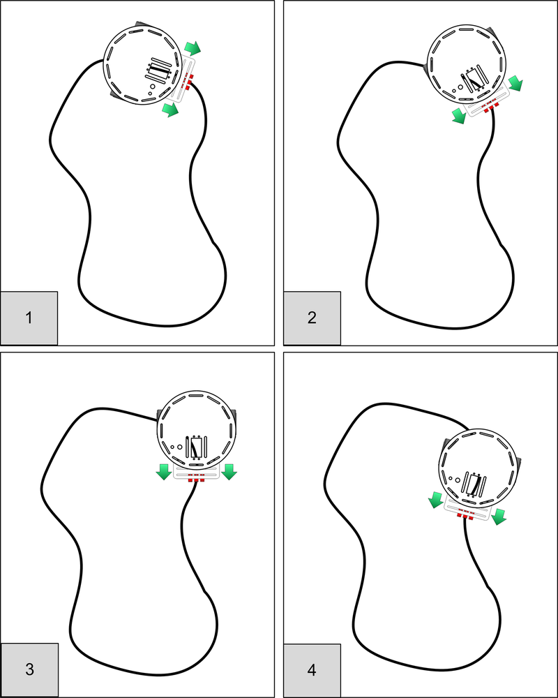
In Panel 1, the robot is approaching a corner but is still centered over the line - the motors are both running at the same speed (indicated by the equal length arrows), and the robot moves straight ahead. The robot has reached the left hand curve in panel 2—the right motor speed is increased, the left slowed to turn the robot to the right. Panel 3 shows the robot completing the turn. In Panel 4, the robot is about to reach a curve to the left where it will continue to adjust motor speeds to keep the sensors over the line.
The illustrations that follow show what happens in more detail. Figure 9-4 shows the location of the sensor with respect to the line when the
robot is centered. The left and right sensors are above the reflective surface. Lots of light
will reflect back to the sensor and the analogRead values are low. The
center sensor is above the black line so has little reflected light, causing the reading to be
high. The difference in readings between left and right indicates drift and is close to zero
so both motors will be driven at the same speed—the robot moves straight ahead. You can read
about how to display sketch data in real time in Seeing Sketch Data.
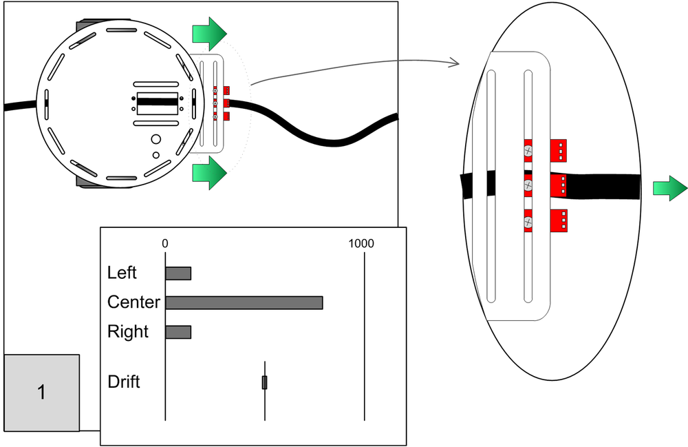
Figure 9-5 shows the robot to the left of the line because the line is
curving to the right. The left sensor detects maximum reflection (the
analogRead value is low). As the center sensor moves towards the edge of
the line, the reflection increases (decreasing the analogRead value). The
right sensor moves towards the line so its reading increases. The drift (the difference
between the left and right) is positive so the left motor speeds up and the right motor slows
down—the robot turns to the right.
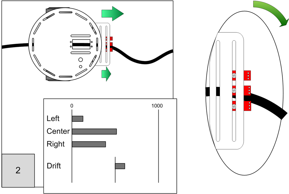
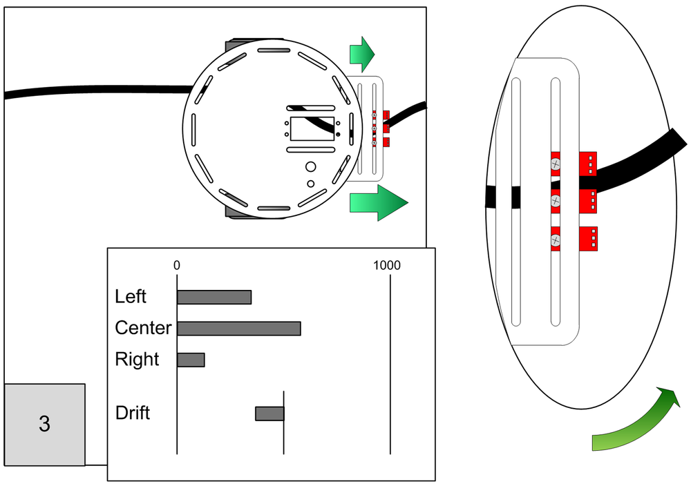
Figure 9-6 shows the robot to the right of the line because the line is
curving to the left. The right sensor detects maximum reflection (the
analogRead value is low). The reading from the center sensor increases as
it moves towards the edge of the line. The left sensor moves towards the line so its reading
increases. The drift is negative so the left motor slows down and the right motor speeds up—the robot turns to the left.
For the robot to successfully follow a curvy line, the movement must be responsive enough to make sharp turns but not so responsive that it zigs and zags its way along even straight lines. Tuning the software to get this just right requires experimentation and patience. The code that follows uses the difference value between the left and right sensors to adjust the differential motor speed. The preceding figures display the relative signal levels from the sensors and the difference value is indicated as 'Drift'. Sensitivity is controlled by mapping the drift value to the actual motor differential speed.
Example 9-3 shows the line sense code that calculates the drift value (you'll see it again in a moment when you see the complete listing for the sketch):
Example 9-3. Line sense code for calculating drift
//returns drift - 0 if over line, minus value if left, plus if right
int lineSense()
{
  int leftVal = analogRead(SENSE_IR_LEFT);
  int centerVal = analogRead(SENSE_IR_CENTER);
  int rightVal = analogRead(SENSE_IR_RIGHT);

  int leftSense = centerVal - leftVal;
  int rightSense = rightVal - centerVal;
  int drift = rightVal - leftVal ;
  return drift;
}
The drift and desired speed are passed to the lineFollow function to
drive the robot. To adjust the motor's sensitivity, drift is divided by a 'damping' factor -
the higher the factor, the less sensitive to drift. Decrease the damping if you need to make
the robot more sensitive, for example, if it is not turning fast enough to follow sharp bends.
Increase the damping if the robot is unnecessarily zig-zagging on straight lines. The drift
value is subtracted from the speed for the left motor and added to the speed of the right
motor to provide a differential speed proportional to drift. The Arduino
constrain function is used to ensure the values remain within the valid
range for speed (0 to 100 %). Depending on the radius of your bends, you may not be able to
completely eliminate the zig-zags.
int lineFollow(int drift, int speed)
{
  int leftSpeed   =  constrain(speed - (drift / damping), 0, 100);
  int rightSpeed  =  constrain(speed + (drift / damping), 0, 100);

  motorForward(MOTOR_LEFT, leftSpeed);
  motorForward(MOTOR_RIGHT, rightSpeed);
}
Example 9-4. Complete listing for code in the myRobotLine main tab
/******************************************************************************
myRobotLine.ino

Robot sketch to follow lines

Michael Margolis 7 July 2012
******************************************************************************/

#include <AFMotor.h>  // adafruit motor shield library
#include "RobotMotor.h"    // 2wd or 4wd motor library

#include "robotDefines.h"  // these were the global defines from myRobot

int speed = MIN_SPEED; // speed in percent when moving along a straight line

/// Setup runs at startup and is used configure pins and init system variables
void setup()
{
  Serial.begin(9600);
  blinkNumber(8); // open port while flashing. Needed for Leonardo only

  lookBegin();  /// added Look tab
  moveBegin();  /// added Move tab
  lineSenseBegin();    // initialize sensors
  Serial.println("Ready");
}

void loop()
{
  int drift = lineSense();
  lineFollow(drift, speed);
}

// function to indicate numbers by flashing the built-in LED
void blinkNumber( byte number) {
   pinMode(LED_PIN, OUTPUT); // enable the LED pin for output
   while(number--) {
     digitalWrite(LED_PIN, HIGH); delay(100);
     digitalWrite(LED_PIN, LOW);  delay(400);
   }
}

/****************************
   Line  Sensor code
****************************/

int damping =  5; //1 is most sensitive, range 1 to 1023)

void lineSenseBegin()
{

}

//returns drift - 0 if over line, minus value if left, plus if right
int lineSense()
{
  int leftVal = analogRead(SENSE_IR_LEFT);
  int centerVal = analogRead(SENSE_IR_CENTER);
  int rightVal = analogRead(SENSE_IR_RIGHT);

  int leftSense = centerVal - leftVal;
  int rightSense = rightVal - centerVal;
  int drift = rightVal - leftVal ;
  return drift;
}

int lineFollow(int drift, int speed)
{
  int leftSpeed   =  constrain(speed - (drift / damping), 0, 100);
  int rightSpeed  =  constrain(speed + (drift / damping), 0, 100);

  motorForward(MOTOR_LEFT, leftSpeed);
  motorForward(MOTOR_RIGHT, rightSpeed);
}
The code for this sketch is derived from the myRobotEdge sketch discussed earlier in this chapter. You can download the example code, locate myRobotLine, open the sketch and upload it to the robot. Or you can derive the sketch yourself:
Open the myRobotEdge sketch in the example code and do a Save As and name it myRobotLine.
Locate the defines for locations of sensors in the robotDefines tab and add the center sensor following the defines for the left and right sensors:
const int SENSE_IR_CENTER = 2;.Replace the main sketch code with the code listed here: Example 9-4.
Compile and upload the code
Place the robot on the surface with the center sensor above the line and switch the power on. After a short delay the robot will move forward and track the line. The robots ability to follow the line depends on many factors:
Line thickness - the optimum thickness depends on the spacing of the sensors. 3/4 inch works well with the robot built as described but you can experiment with different line widths and different sensor spacing.
Sensor height above surface - the sensors are less sensitive when further from the surface- try using spacers to move the sensors closer to the surface.
Speed - too slow and the robot may not have enough torque, too fast and the robot will overshoot the line. Try running at a speed around 10% above minimum speed if the robot appears to be sluggish - in the top of the main tab, change the code to :
int speed = MIN_SPEED+10;.Robot over sensitive - if the robot follows the line but zig-zags excessively , increase the damping value in the line sensor code in the main tab. Try larger values until you find a range that works. Note that you may need a different damping value if you change the speed.
Robot not sensitive enough - if the robot drifts off the line, decrease the damping value in the line sensor code in the main tab. Try smaller values until you find a range that works. Note that you may need a different damping value if you change the speed.
Viewing the values of variables in real time makes it much easier to tune or debug your code. You can view values printed to the serial port on the Serial Monitor, but that can be difficult to read if these values are changing quickly. Appendix C describes how to use a Processing sketch to display data as bar charts, similar to the that shown earlier in this chapter (see Figure 9-4).
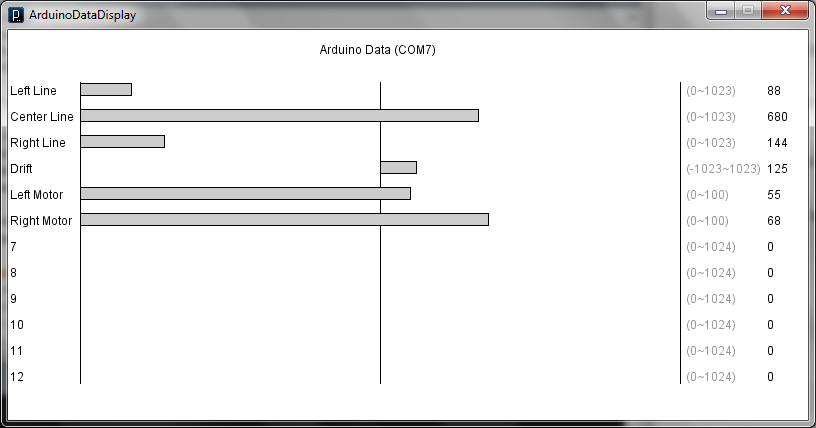
Here is how the line following sketch should be modified to display the sensor value:
Add the DataDisplay tab to the sketch (the myRobotLineDisplay sketch in the example code download (How to Contact Us) has this tab added as well as all the other code changes that follow).
In the main sketch, add constants identifying the list of items to be displayed, labels for each item, and the minimum and maximum values. Example 9-5 shows the constants used to produce the display in Figure 9-7.
Example 9-5. Constants for display labels
enum {DATA_start,DATA_LEFT,DATA_CENTER,DATA_RIGHT,
      DATA_DRIFT,DATA_L_SPEED,DATA_R_SPEED, DATA_nbrItems};

char* labels[] =
  {"", "Left Line", "Center Line", "Right Line","Drift", "Left Speed", "Right Speed"};

int minRange[] =
  {0,            0,             0,            0,  -1023,            0,             0};

int maxRange[] =
  {0,         1023,          1023,         1023,   1023,          100,           100};
Add the function call shown in Example 9-6 to setup().
Example 9-6. Adding a call to begin the data display
dataDisplayBegin(DATA_nbrItems, labels, minRange, maxRange );
You can then call the sendData function to send the values you want to display.
Example 9-7 shows the lineSense() function updated to send sensor data.
Example 9-7. lineSense now sending sensor data
//returns drift - 0 if over line, minus value if left, plus if right
int lineSense()
{
  int leftVal = analogRead(SENSE_IR_LEFT);
  int centerVal = analogRead(SENSE_IR_CENTER);
  int rightVal = analogRead(SENSE_IR_RIGHT);

  sendData(DATA_LEFT, leftVal);      // send left sensor value
  sendData(DATA_CENTER, centerVal);  // send center sensor value
  sendData(DATA_RIGHT, rightVal);    // send right sensor values


  int leftSense = centerVal - leftVal;
  int rightSense = rightVal - centerVal;
  int drift = rightVal - leftVal ;

  sendData(DATA_DRIFT, drift);    // send drift sensor values

  return drift;
}
Motor speed can be displayed by adding calls to sendData in the lineFollow function as shown in Example 9-8.
Example 9-8. Adding support for displaying motor speed
int lineFollow(int drift, int speed)
{
  int leftSpeed   =  constrain(speed - (drift / damping), 0, 100);
  int rightSpeed  =  constrain(speed + (drift / damping), 0, 100);

  sendData(DATA_L_SPEED, leftSpeed);   // send left motor speed
  sendData(DATA_R_SPEED, rightSpeed);  // send right motor speed

  motorForward(MOTOR_LEFT, leftSpeed);
  motorForward(MOTOR_RIGHT, rightSpeed);
}